
Maglock Wire Gauge: How to Size Power Runs by Distance

There is no single correct wire gauge for a maglock. The right gauge depends on three things: the lock’s operating voltage, the total current on the circuit, and the one-way distance from the power supply to the lock. For a typical 24 VDC lock drawing about 500 mA, 18 AWG covers most door runs up to roughly 100 feet. Longer runs or heavier loads need 16 AWG or thicker. This guide shows you how to work it out, how to check it, and what to do when a lock will not hold.
TL;DR
- Size the wire from voltage, total circuit current and one-way distance. A chart or calculator gives the answer, not a rule of thumb.
- Keep voltage drop to about 5% of supply voltage. SDC’s power guide gives that as its rule of thumb and says to measure voltage at the locking hardware.
- 24 VDC tolerates longer runs than 12 VDC. Cable such as CAT5/6 and 22 or 24 AWG is too thin for most lock power runs over distance.
- Follow the manufacturer’s table for the exact lock model, and confirm local requirements with the authority having jurisdiction.
Why wire gauge matters for a maglock
A maglock holds a door shut with an electromagnet. Holding force depends on the current the coil actually receives. If the wire is too thin for the distance, resistance in the conductor eats part of the supply voltage before it reaches the lock. That loss is voltage drop.
The symptoms are familiar to anyone who has serviced a door. The lock holds when you test it on the bench and weakly on the door. It buzzes, runs warm or releases under a firm pull. SDC’s guide names inadequate voltage as a cause of hot, erratic or non-operating devices. Replacing the lock does not fix a wiring problem.
Gauge is chosen at rough-in, when changing it costs a pull of wire. After the ceiling is closed and the door is finished, it costs a service call. That is the reason we size the run on paper before any cable is pulled. Our low voltage rough-in guide covers where that decision sits in the project.
The three inputs that set the gauge
1. Operating voltage
Most commercial maglocks run on 12 or 24 VDC. Many are field-selectable. The Securitron V2M1200/1290 series, for example, operates at 12 or 24 VDC with a switch and its instructions say to confirm the onboard board is set to the voltage you intend to use. The switch position must match the power supply output.
Voltage matters because, for the same power, a 12 V lock draws about twice the current of a 24 V lock. Double the current means double the voltage lost per foot of wire, on a supply that has half the headroom. Guidance from lock suppliers is consistent that 24 VDC gives better stability and allows longer runs than 12 VDC. When a door is far from the power supply, choosing 24 V is often the cheapest fix.
2. Total current on the circuit
Add the current of everything sharing the pair of wires: the lock, and any other powered device on that run. Do not use the lock’s holding force or its “typical” current. Use the maximum figure on the data sheet or installation instructions.
SDC recommends adding a 30% safety margin when calculating system current load. Other suppliers suggest 20% when sizing power supply capacity for several locks. The margins are not in conflict. Pick one, state it in your design notes and apply it consistently.
Multiple locks on one supply need more care. SDC’s wire-gauge chart instructions say that when a gauge or distance is inadequate, you divide the locks into two or more separate circuits and size each circuit on its own. That is usually better than jumping up a wire size for a long shared run.
3. One-way distance
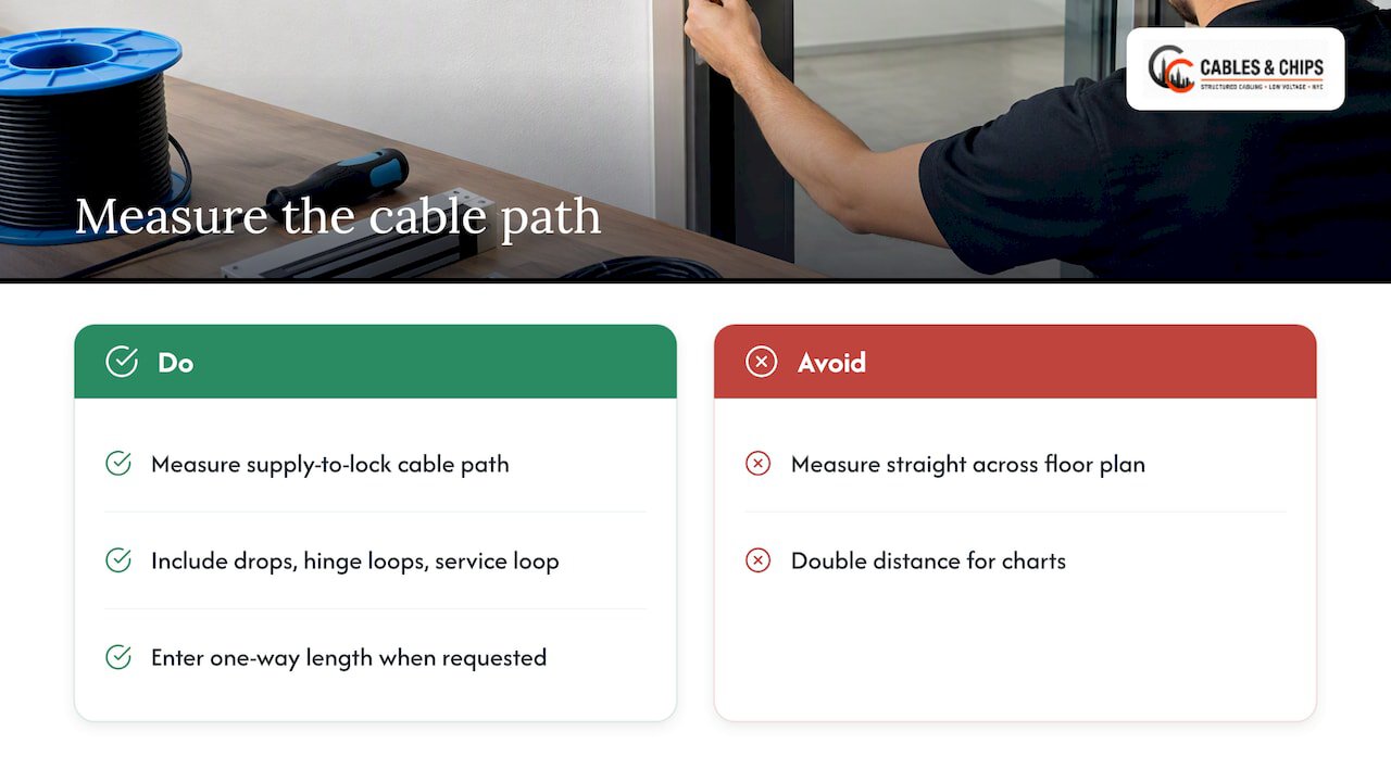
Measure the cable path from the power supply output to the lock, not the straight-line distance across the floor plan. Include vertical drops, door hinge loops and the service loop in the ceiling. Charts list the one-way distance, and they already account for current flowing out and back. If you use a calculator that asks for “one-way wire length,” give it the one-way figure, as LifeSafety Power’s calculator does.
Maglock wire gauge by distance: a reference example
Manufacturer tables are model-specific, so treat any table as an example. SECO-LARM’s magnetic lock manual gives this minimum wire size for a lock drawing 500 mA at 24 VDC:
| One-way distance | Minimum wire size (24 VDC, 500 mA) |
|---|---|
| 25 ft | 20 AWG |
| 50 to 100 ft | 18 AWG |
| 150 ft | 16 AWG |
| 200 to 250 ft | 14 AWG |
| 300 ft | 12 AWG |
| 400 ft | 10 AWG |
These figures come from the SECO-LARM installation manual for that load. A lock with a higher current draw, or the same lock set to 12 VDC, moves every row toward a thicker wire.
Two practical points follow from the table:
- 18 AWG is a sound default for ordinary door runs. One hardware supplier’s instructions specify 18 AWG solid wire for power and warn that 22 AWG, 24 AWG and CAT5/6 are not large enough over longer distances.
- Do not borrow wire sizes from the data cable. Reader and request-to-exit signals can run on small conductors. The lock power cannot.
Worked example: checking voltage drop yourself
Charts are fast, but you should be able to verify one. Voltage drop follows Ohm’s law: current times the resistance of the conductor. The wire carries current to the lock and back, so use twice the one-way length.
Example A: 24 VDC lock, 500 mA, 100 ft one-way, 18 AWG
- Copper 18 AWG has a resistance of roughly 6.4 ohms per 1,000 ft.
- Loop length is 200 ft, so resistance is about 1.28 ohms.
- Drop is 0.5 A times 1.28 ohms, about 0.64 V.
- That is about 2.7% of 24 V, well inside a 5% limit. The lock sees about 23.4 V.
This agrees with the SECO-LARM table above, which lists 18 AWG for 50 to 100 ft at that load.
Example B: the same lock power at 12 VDC
- The lock draws about 1 A to deliver the same power.
- Same 18 AWG, same 100 ft: drop is about 1.28 V.
- That is about 10.7% of 12 V. It fails a 5% limit, and the lock may be marginal.
Switching to 24 V, or moving to a heavier gauge, fixes it. The 12 V lock on thin wire is one of the most common reasons a door holds unevenly.
For a second reference, LifeSafety Power’s worked example runs 100 ft of 22 AWG at 0.3 A from a 25.0 V supply. It calculates about 0.98 V of drop and 24.02 V at the lock.
For real projects, use a calculator rather than hand math on every door. SDC’s voltage drop calculator lets you enter any three values to find the fourth. It accepts wire-run lengths only up to 999 ft, which is more than enough for a single door.

Which drop limit should you use?
You will see more than one limit. SDC’s chart is based on a 5% voltage drop. Hager’s wire-gauge chart is based on an industry-standard 10% drop. The stricter figure is the safer design target for a maglock, because holding force is the whole job of the device.
The better test is the lock’s published minimum operating voltage. LifeSafety Power points out that the minimum operating voltage, not just whether the magnet energizes, controls the allowable drop. It also checks end voltage when the system is on backup battery. A door that holds at 24.0 V from mains may sit lower when the supply is running on batteries. Size for the worst case.
A five-step method for each door
We use the same sequence on every access-controlled opening. Our access control wire gauge steps go deeper, and this is the short version.
- Read the lock’s data sheet. Record voltage options, maximum current at each voltage and the minimum operating voltage.
- List everything on the circuit. Add lock current and any other powered device sharing the pair. Apply a 20% to 30% margin.
- Measure the cable path. Use the real route from power supply to lock, one way.
- Find the gauge. Use the manufacturer’s chart for that model, or the SDC calculator. If the result is heavier than the conduit, box or hinge can handle, split the circuit or raise the voltage.
- Test after installation. Measure voltage at the lock with the door system energized. Compare it with the calculation and record it in the closeout documents.
Step five is the one that gets skipped. SDC’s guidance is to measure voltage at the locking hardware, not at the power supply. A healthy reading at the supply proves nothing about the door. Our as-built documentation guide explains how to hand those readings to the building team.
Why NEC ampacity charts mislead on low voltage
A common mistake is to size lock wire from the ampacity charts used for line-voltage AC. Those tables answer one question: how much current can a conductor carry without overheating? Low-voltage DC circuits fail for a different reason. Hager Companies notes that using ampacity charts designed for 110V/220V AC for low-voltage DC ignores voltage drop, which dominates at low voltage.
A 500 mA lock will not overheat 22 AWG wire. It will starve at 100 ft. The wire is safe and the door is unreliable. Size for drop, then confirm the cable type is allowed for the pathway.
Wire, power and code: what to check in the U.S.
Wire gauge is one piece of a compliant door. A maglock is part of the means of egress, and the code treats it accordingly.
- Installation standard. The Locknetics MG600 / MG1200 guide says wiring must comply with ANSI/NFPA 70 and with the local authority having jurisdiction. In New York City, that is the Department of Buildings and the Fire Department for the permit and inspection side of the job.
- Egress. NFPA 101 sets requirements for sensor-release electrical locking systems. They include fail-safe operation, so the lock releases on power loss, and manual or contactless release devices. The manual release must carry a PUSH TO EXIT sign and sit 40 to 48 inches above the floor.
- Listings. UL states that electrically locked egress doors must be listed to UL 294, and electromagnetic locks are typically listed to UL 1034. Confirm the lock, power supply and release devices are listed for the combination you install.
Code editions and local amendments change. Check the current adopted edition with the authority having jurisdiction and your fire protection engineer before you finalize a door’s hardware schedule. Our access control cabling requirements guide lays out the cabling side of those requirements.
Separation and pathways
Lock power conductors share ceilings and risers with other systems. Keep them away from line-voltage conductors as required. We cover when U.S. codes call for two inches of separation in a separate guide. A heavier-gauge pair also takes more room in a conduit, so plan that at rough-in, not on the day of install.
Power supplies, fuses and surge suppression
Gauge decisions interact with the rest of the circuit.
- Power supply capacity. Total the connected load with margin, as above. A supply sized to the minimum will sag under inrush from several locks and reader controllers.
- Fusing. Schlage’s maglock setup for its reader controller shows a 0.5 A fast-acting fuse isolating the lock’s power. Fuse to the manufacturer’s diagram, not by habit.
- Suppression. The same guide says transient suppression reduces back EMF from lock coils. That protects controllers and relays when the circuit is switched.
- Polarity. Keep the lock on the switched positive side of the circuit, and do not break the ground wire to release the lock. Installers in the field repeat this rule often, because breaking the wrong leg gives odd behavior and shortens relay life.
If your readers sit on PoE, voltage drop works differently, because the budget is split between the switch, the cable and the device. Our PoE voltage drop guide covers it. Door controllers powered over Ethernet do not remove the need to size the separate lock power run.
The same sizing logic applies to any credential-controlled device. Access control for private EV chargepoints with RFID is one example outside the building envelope. There too the power and signal wiring have to be designed for the distance.
When a maglock will not hold: a wiring checklist
If a maglock is weak or intermittent, work through the supply path in order. Securitron’s instructions list the first things to check: voltage switch position, power supply voltage, wire gauge for the run, and armature plate alignment.
- Switch position. A 12/24 V lock set to 12 V on a 24 V supply is a fault. A lock set to 24 V on a 12 V supply will not hold.
- Voltage at the supply. Confirm the output under load, not unloaded.
- Voltage at the lock. Measure at the lock terminals with the system energized. Compare with the minimum operating voltage. A gap of more than about 5% of supply voltage points to the wire.
- Wire gauge and length. Compare what was installed with the chart. Look for undersized splices, a thin pigtail at the lock or a data cable pressed into service as power.
- Connections. Look for loose terminals, wire nuts in the ceiling and corroded splices on older runs.
- Armature plate. Check alignment and that the plate sits flush against the magnet face. Misalignment weakens holding force regardless of voltage.
Abandoned and unlabeled cable makes this harder. When one pair in a bundle is unknown, the quickest honest answer is to test and label the run. Our cable testing and certification work covers data cabling, and the same discipline of testing and labeling applies to lock power runs.
What to do when the run is too long
Sometimes the calculation says the door is simply too far. You have four options, in the order we usually consider them:
- Raise the voltage. Move from 12 to 24 VDC if the lock supports it, and update the supply and the switch position.
- Move the power supply. Put the supply in the nearest telecom room or a local enclosure. A supply that serves several nearby doors shortens every run.
- Split the circuit. Give far doors their own pair, as the SDC chart instructions advise.
- Increase the gauge. Go to 16 AWG or thicker. Check that terminals, conduit and the door’s hinge loop can take it.
Two cores doubled up can also reduce resistance, as installers often do with multicore cable. That is a field fix, not a design. Record it, and verify the voltage at the lock.
Our perspective: size the door, not the average
In our experience on commercial work in New York City, lock power problems seldom come from a bad lock. They come from a decision made too early with too little information: a standard cable ordered for the whole floor, a power supply placed where it was convenient, or a 12 V setting left at the factory default. The fix costs little at rough-in and a lot after finish.
We size every access-controlled opening individually. We use the manufacturer’s chart for the exact lock, the real cable route, and a margin on current. Then we measure voltage at the lock when the system is live, and we put that number in the documentation. A door with a recorded reading is a door the next technician can service without guesswork.
Our position is simple. The cable is part of the lock. In dense Manhattan buildings with long risers, shared pathways and tight telecom rooms, that matters more than the hardware brand does. The cable is also the part nobody sees after the ceiling goes up, so it has to be right the first time.
— Ken
Get the door runs right before the ceiling closes
If you are planning an office build-out, a relocation or an access control upgrade in New York City, we can size, install, test and document the lock power and data cabling together. See our CCTV and access control installation service, or browse the full list of low voltage services and ask for a no-obligation site survey.
FAQ
What wire gauge should I use for a 24V maglock?
For a lock drawing about 500 mA at 24 VDC, SECO-LARM’s table calls for 18 AWG from 50 to 100 ft, 16 AWG at 150 ft and 14 AWG at 200 to 250 ft. Use the table for your lock model, because current draw varies. Verify voltage at the lock after installation.
Can I use CAT6 cable to power a maglock?
It is not a good idea. Supplier instructions warn that 22 AWG, 24 AWG and CAT5/6 are too thin for longer lock power runs. Use CAT6 for readers and network devices, and a separate, properly sized pair for the lock.
How much voltage drop is acceptable for a maglock?
A common design limit is 5% of supply voltage, the basis of SDC’s chart and its power guide. Hager’s chart uses 10%. Whatever you choose, the voltage at the lock must stay above the manufacturer’s minimum operating voltage, including on backup power.
Is 12V or 24V better for a maglock?
For long runs, 24 VDC. The same power at 12 V needs about twice the current, so the drop on a given wire is about twice as large and the margin is half as big. Use 12 V only where the lock, supply and run are suited to it, and make sure the lock’s voltage switch matches the supply.
Does a maglock need to be fail-safe?
In the means of egress, NFPA 101 requires sensor-release locking systems to unlock on power loss and to have manual or contactless release devices. The exact requirement for a given door depends on the occupancy and the adopted code edition. Confirm it with the authority having jurisdiction before you specify hardware.
Sources
- SDC wire gauge charts and Ohm’s law (PDF)
- SDC Access Control Power Guide (PDF)
- SDC wire gauge size and distance chart (PDF)
- SDC access control system calculators
- Securitron V2M1200/1290 installation instructions (PDF)
- SECO-LARM magnetic lock installation manual (PDF)
- Locknetics MG600 / MG1200 user guide (PDF)
- Maglock assembly instructions (PDF)
- Magnetic lock wiring diagrams and power requirements (PDF)
- Hager wire run gauge guide (PDF)
- LifeSafety Power: Understanding FlexCalculator Part 1
- Schlage RC Pure IP reader controller user guide (PDF)
- NFPA 101 first revision report on sensor-release locking (PDF)
- UL: Special Locking Arrangements (PDF)