
3–5V Margin: Calculate PoE Voltage Drop for Installers
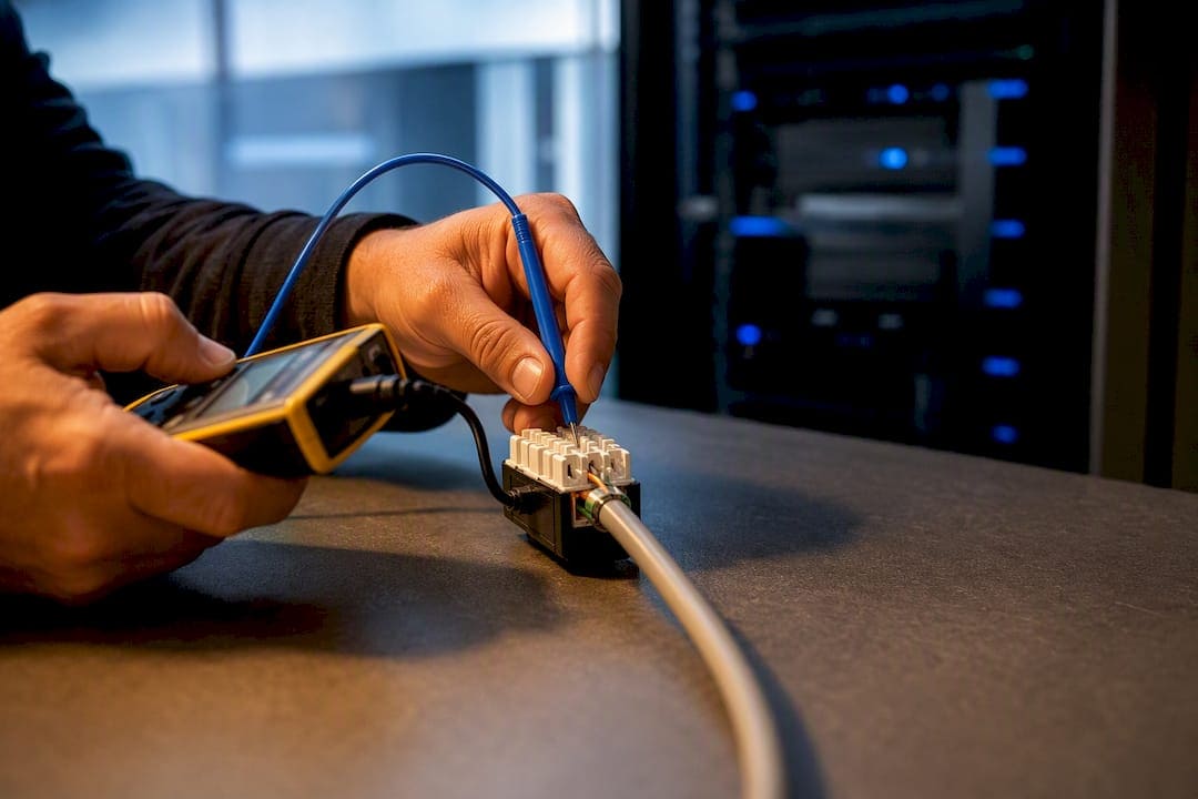
Yes, PoE voltage drop under load is real, and it scales directly with current and loop resistance through V = I × R. Measure voltage at the powered device while it draws its actual operating current, not at idle, and compare that reading against the IEEE minimum for its power class. If the number comes in low, start with the cheap fixes first: swap in a known-good short patch cable, re-crimp the terminations, or shorten the run before you assume the switch or power supply is at fault.
TL;DR:
- Voltage drop in PoE circuits increases with higher current, longer loop resistance, and temperature, often causing underpowered or unstable devices.
- Using thicker copper conductors like 23 AWG and minimizing bundling helps reduce resistance and heat, which in turn lowers voltage loss under load.
- Testing with real load conditions while devices are drawing power reveals more accurate voltage drops than idle measurements, preventing false positives.
- Proper re-termination, shorter cable runs, and avoiding CCA cabling can solve most issues related to excess voltage drop in PoE systems.
- Planning for a margin of 3 to 5 volts above the IEEE minimum at the powered device ensures reliable operation despite installation variations and environmental factors.
How Voltage Drop Works in PoE: Loop Resistance and I²R Heating
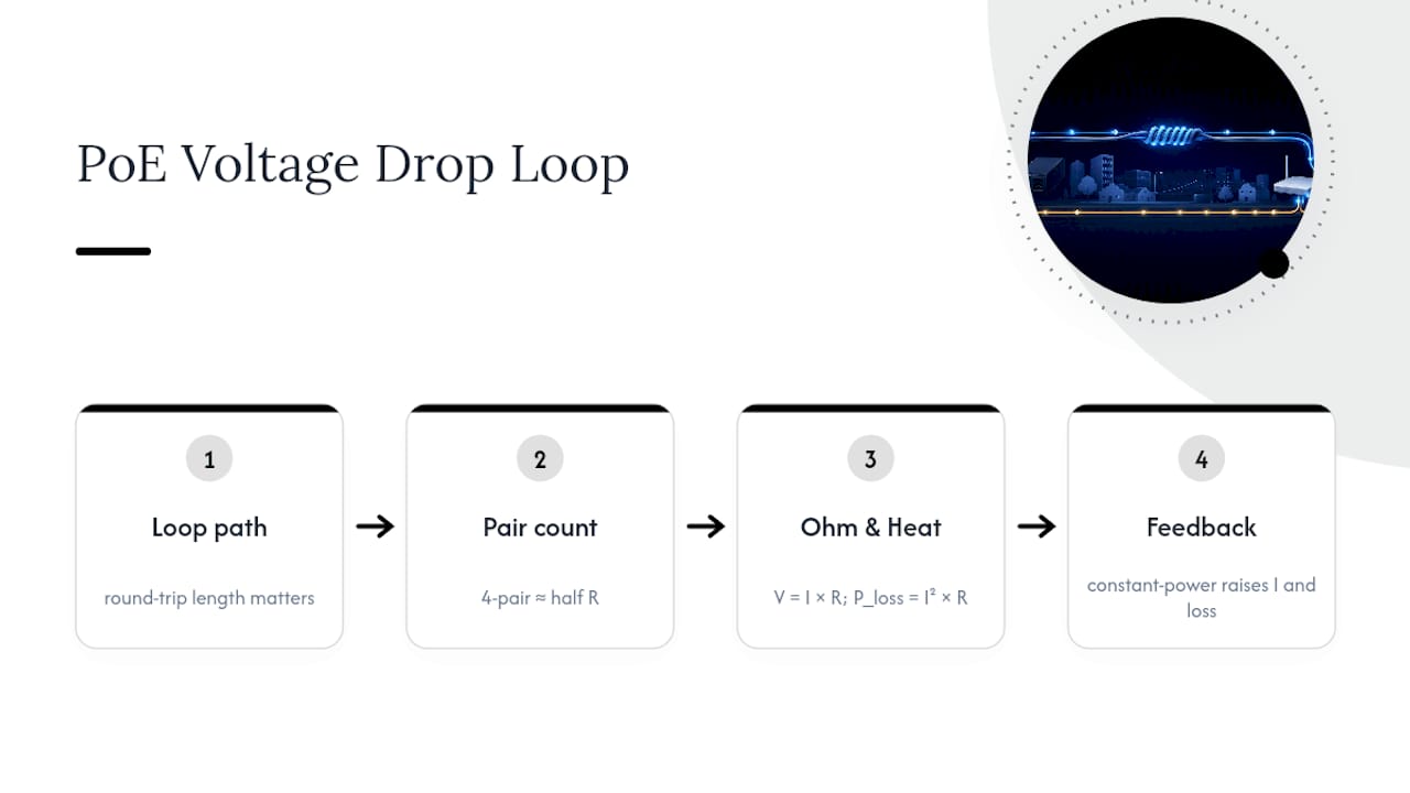
Every PoE circuit is a loop. Current leaves the switch or midspan injector on one conductor path, passes through the powered device, and returns on a second path. That round-trip distance, not the one-way cable length, is what determines loop resistance. On 2-pair PoE (802.3af/at), two conductors carry the current in each direction. On 4-pair PoE (802.3bt), current splits across four conductors each way, which cuts effective resistance roughly in half compared to the same cable run on 2-pair.
The governing equation is simple: V = I × R. Push more current through a fixed resistance and the voltage drop rises in direct proportion. Power lost as heat follows a related equation, P_loss = I² × R, which means loss grows with the square of current. Double the current and you quadruple the heat, not just double it.
This matters because most PoE-powered devices behave as constant-power loads, not constant-resistance loads. As voltage sags, a device pulls more current to hold its power draw steady, which increases I²R loss further and drops voltage even more. It’s a small feedback loop, and it’s why marginal installations sometimes work fine at idle but fail the moment a camera’s IR illuminators or a phone’s display kicks on.
Copper resistance itself isn’t fixed. It rises with temperature at roughly 0.00393 per degree Celsius, so a cable bundle running warm inside a ceiling plenum has measurably higher resistance than the same cable at room temperature. That single fact connects directly to the thermal problems covered later in this guide.
PoE Standards and Power Budgets: 802.3af, 802.3at, and 802.3bt
The IEEE 802.3 family sets guaranteed minimums, not typical performance. IEEE Std 802.3-2022 defines the PSE-side voltage and power delivery, and each type carries a different budget for cable and connector loss.
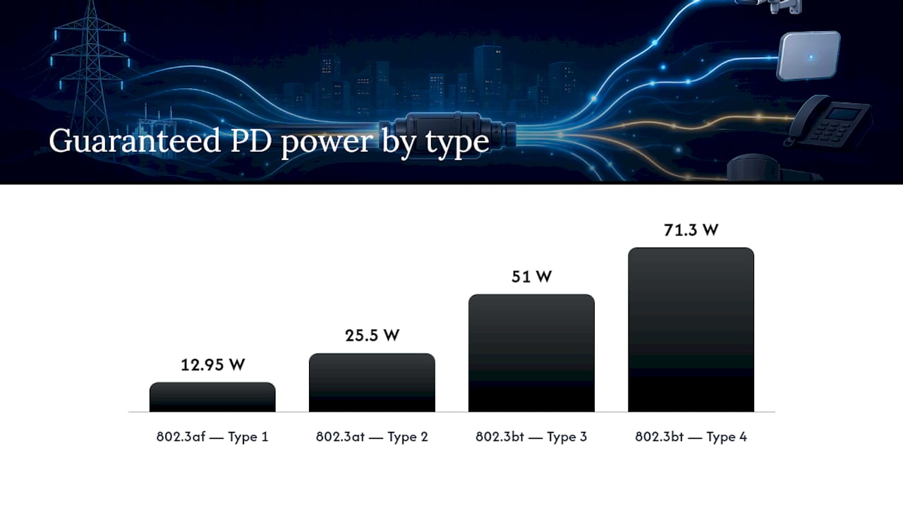
Roughly speaking, 802.3af (Type 1) guarantees about 12.95 W at the powered device, 802.3at (Type 2) guarantees around 25.5 W, and 802.3bt Type 3 and Type 4 guarantee roughly 51 W and 71.3 W respectively. The gap between what the PSE pushes out and what the PD is guaranteed to receive is the standard’s built-in allowance for cable and connector loss, calculated against a worst-case corner scenario: maximum cable length, minimum conductor gauge, and elevated temperature all at once.
Real installations almost never hit that corner case simultaneously. Typical installed systems with solid-copper cable and clean terminations often show losses of only 2 to 3 percent, versus the roughly 15 percent the standard’s worst-case math allows for. That margin is your buffer, and it’s also why a system that passes certification can still fail under specific load combinations if the installation quality slips.
802.3bt’s shift to 4-pair delivery is the single biggest structural improvement in the standard’s history for voltage drop, since splitting current across twice as many conductors cuts loop resistance substantially. Autoclass and LLDP-based power negotiation also help by letting the PSE allocate power based on what the PD actually reports needing, rather than reserving the full class maximum on every port.
What Actually Drives Excess Drop in the Field
Cable gauge is the first variable to check, and it’s often overlooked because most installers assume “Cat6 is Cat6.” It isn’t. Conductor resistance per unit length varies by AWG size, and thinner conductors mean more resistance and more drop at the same current.
Copper-clad aluminum, sold as a cheaper alternative to solid copper, has meaningfully higher resistance than solid copper of the same gauge, and it’s the most common hidden cause of PoE failures on long or high-power runs. A detailed breakdown of solid versus stranded and CCA conductor behavior is worth reviewing before you spec any long PoE run, and choosing the right cable type for extended runs matters more for PoE loads than for data-only links.
Bundling adds a second, less obvious layer of risk. Dozens of PoE cables run tight together in a conduit or J-hook generate collective heat that raises the ambient temperature each cable sees, and that heat drives up conductor resistance, which increases I²R loss, which generates more heat. The Ethernet Alliance and IEEE tutorial data documents exactly this feedback pattern in high-density Type 3 and Type 4 bundles, and it’s the reasoning behind NEC 725.144 bundle-size derating tables. Beyond gauge and bundling, watch for pair imbalance from mixed conductor quality and simple connector resistance at poorly seated RJ45 terminations, which can add more resistance than several meters of extra cable.
How to Calculate PoE Voltage Drop Step by Step
The math behind PoE voltage drop under load uses four equations in sequence:
- Loop resistance: Rloop = R_per_meter × L × 2 (the ×2 accounts for the round trip)
- Current draw: I ≈ P_PSE ÷ V_PSE, keeping in mind that constant-power PDs will draw more current as voltage sags
- Voltage drop: Vdrop = I × Rloop
- Power lost as heat: P_loss = I² × Rloop
Here’s how that plays out across three common scenarios:
Run the numbers yourself against a PoE voltage drop calculator that models temperature-adjusted resistance, since ambient heat inside a ceiling or bundle can push the actual figure higher than a room-temperature estimate.
The margin check matters more than the raw drop number. Compare your calculated PD voltage against the IEEE minimum for that class, then build in extra headroom, since connector and termination resistance at each RJ45 jack typically isn’t captured in a straight per-meter calculation. Two or three degraded connections in a run can add the equivalent of another 10 to 15 meters of cable resistance without changing the measured length at all.
Testing PoE Voltage Under Real Load
Open-circuit voltage tells you almost nothing useful. A switch port can show a clean 53 volts with no device attached and still sag well below spec the instant a camera or phone starts drawing current, which is why testing under sustained load rather than at idle is the only reliable diagnostic method. Users troubleshooting PoE-powered storage devices have reported hard drives failing to spin up specifically because voltage collapsed once real load hit the line, even though the connection tested fine at idle.
A practical field kit for this work includes:
- A dedicated PoE load tester that simulates a PD’s actual power draw
- A digital multimeter for spot voltage checks at accessible test points
- A clamp meter for non-invasive current readings on live runs
- A TDR or wiremap tester to rule out physical cable faults
- Switch CLI access for
show power inlineor equivalent commands to confirm what the PSE thinks it’s delivering
The procedure itself is straightforward: measure PSE output voltage first, then measure voltage at the PD while it’s under actual operating load, then walk the segments in between. Test at the patch panel, at the keystone jack, and at the device end to isolate exactly where the drop concentrates. A drop that jumps sharply at one segment almost always points to a bad termination or a damaged connector rather than distributed cable resistance.
Pro Tip: Test load with the device performing its most power-hungry task, not sitting idle. A PTZ camera panning or a phone at full ring volume draws meaningfully more current than the same device at rest, and that’s the load condition where marginal cabling actually fails.
Full cable plant testing and certification workflows extend this same logic across an entire building’s cable plant rather than one run at a time.
Troubleshooting Checklist for Excess Voltage Drop
- Poor terminations. Symptom: drop concentrated at one segment. Test: measure voltage before and after each connector. Fix: re-terminate; this alone resolves roughly 80 percent of single-run PoE issues.
- Excessive length or wrong gauge. Symptom: drop distributed evenly across the run. Test: measure total loop resistance against the calculated expectation for that cable type. Fix: shorten the run or move to a lower-resistance conductor.
- CCA cable. Symptom: drop far exceeds calculated solid-copper expectations. Test: check cable jacket markings or strip and inspect the conductor. Fix: replace with solid copper; there’s no reliable workaround.
- Switch PSU or port budget limits. Symptom: multiple ports underperform simultaneously. Test: check switch CLI power allocation reporting. Fix: redistribute load or add a midspan injector.
- Bundle heating. Symptom: drop worsens as more devices power on nearby. Test: check bundle temperature and density against NEC derating tables. Fix: split bundles or add ventilation.
- Damaged conductors. Symptom: intermittent or unstable voltage. Test: TDR trace for faults. Fix: replace the cable.
When length or power demand consistently exceeds what copper can handle cleanly, it’s time for a design change: PoE extenders, local power injection at the device, or a move to fiber with local PSE power for the longest or highest-power runs.
Installer Rules of Thumb for PoE Voltage Margin
Some installers specify 23 AWG Cat6A for high-power or long-distance runs, aiming for 3 to 5 volts of margin at the PD under full load rather than the bare minimum. That margin absorbs the temperature swings, connector wear, and future load increases that a spec-sheet calculation alone won’t catch.
The field fix sequence stays consistent across most service calls: re-crimp the questionable end first, swap in a known-good short patch cable second, then take segment-by-segment voltage checks to isolate the fault before any cable gets pulled. Replacing a full run is the last step, not the first.
Every job includes certification testing and as-built documentation, because a voltage-drop problem discovered six months after installation is far cheaper to diagnose when the original test results and cable routes are on file. That documentation habit, built over more than 40 years of commercial low-voltage work, tends to matter more during a troubleshooting call than any single tool in the kit.
The Standards Give You a Floor, Not a Design Target
The most common mistake in PoE planning is treating the IEEE guaranteed minimums as a design target instead of a safety floor. Engineers who spec a run to just barely clear 802.3at’s minimum PD voltage are betting that nothing ever goes wrong: no CCA substitution during procurement, no bundle added later, no summer heat wave in the ceiling plenum. That bet loses more often than the spec sheets suggest.
The conventional advice, “follow the standard and you’re fine,” undersells how much of PoE performance depends on installation quality rather than the standard itself. The Ethernet Alliance data makes this explicit: typical losses run at 2 to 3 percent while the standard budgets for roughly 15 percent, which means the standard was never describing your install. It was describing the worst plausible one.
What should change in practice is simple. Calculate loop resistance before the job, not after a complaint call. Test under real load, not open circuit. And treat 4-pair delivery and solid copper as the default for anything running high-power PoE++, not an upgrade reserved for problem jobs. The margin is cheap to build in up front and expensive to chase down later.
— Ken
Fixing PoE Voltage Drop Problems in NYC Buildings
Some contractors specialize in diagnosing PoE voltage drop issues that cause underperformance after networks test fine on paper. Their technicians measure loop resistance, test under actual load, and isolate problematic cable segments, whether bad terminations or bundle heating.

If a device is browning out, rebooting under load, or failing to power on despite testing fine at idle, that’s a voltage-drop signature worth investigating before more equipment gets swapped unnecessarily. Cables and Chips offers cable testing and certification alongside re-terminations, CAT6A upgrades, and bundle remediation for buildings across New York City, backed by more than 40 years of commercial low-voltage experience. Request a site survey through our full services page and get a documented diagnosis before the next service call, not after.
Standards and Tools Worth Bookmarking
For readers who want to verify the numbers themselves, the IEEE 802.3-2022 standard is the authoritative source for guaranteed power classes. The Ethernet Alliance PoE cable-loss whitepaper models real-world system loss against the standard’s worst case, and the IEEE practical PoE tutorial covers thermal behavior in depth. A PoE voltage drop calculator is the fastest way to model a specific run before you commit to cable and terminations.
Sources
- PoE Cable Losses (Ethernet Alliance whitepaper)
- Practical PoE tutorial (IEEE 802 tutorials)
- PoE Power Loss: Common Causes and How to Fix Them (CableTestShop)
- PoE Voltage Drop Calculator (Pingdo)
FAQ
What causes voltage to drop under load?
Voltage drop under load happens because current flowing through a resistive conductor loses energy proportional to that resistance, following V = I × R. In PoE specifically, higher current draw from the powered device combined with cable and connector resistance produces a larger drop than the same cable shows at idle.
Can you test PoE with a multimeter?
Yes, a digital multimeter can measure DC voltage at accessible test points, but it only gives a meaningful reading if the powered device is drawing its actual operating load at the time of the test. An open-circuit reading with no device attached will look fine even on a cable that fails under real power draw.
What is a voltage drop on a load?
A voltage drop on a load is the difference between the source voltage and the voltage actually available at the device, caused by resistance in the conductors between them. In PoE, that means the difference between what the switch outputs and what the camera, phone, or access point actually receives after cable and connector losses.
When should you worry about voltage drop?
Worry when measured PD voltage falls close to the IEEE minimum for that device’s power class, or when a device works at idle but fails, reboots, or underperforms once it draws full power. Building in 3 to 5 volts of margin above the standard minimum, as installers typically target, gives enough buffer to absorb temperature swings and aging connections before they become failures.