
US Installers: 5 Steps to Size Access Control Wire Gauge
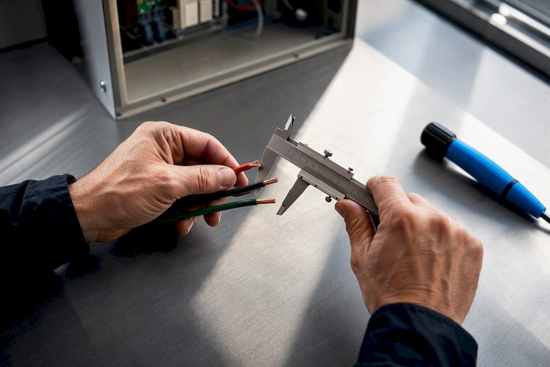
Select conductor size based on total circuit current, the one-way distance to the farthest device, and the system voltage, then verify with a voltage-drop calculation. For most installs, that means 18 AWG for lock power and 22 AWG shielded for readers unless distance or load pushes you to upsize. Confirm stranded pure copper conductors and check the run against NEC and your local AHJ before you close up the wall.
TL;DR:
- Using a round-trip distance instead of one-way measurement is essential to accurately calculate voltage drop and prevent lock failures.
- Circuit segregation is critical, with lock power on its own fuse and label every conductor at both ends during installation to avoid intermittent problems.
- Most access control devices require specific gauges: 18 AWG for maglocks and strikes over 100 ft, and 22 AWG shielded for low-current readers and sensors.
- Undersized wires risk overheating and potential fire hazards, especially if additional devices are added or if environmental factors like heat and moisture are not considered.
- Proper planning, including site surveys and documented as-built layouts, helps avoid costly re-pulls and ensures compliance with NEC and local AHJ wiring standards.
Access Control Wire Gauge Selection: The Step-by-Step Workflow
Every access control run should go through the same five checks before you pull cable. Skipping any one of these steps is how a system passes bench testing and then fails at the door six months later, usually right after a lock starts drawing more current under load than it did on day one.
-
List every device on the circuit and pull its amp draw from the datasheet. A maglock, a strike, a REX sensor, and a door contact all draw differently, and stacking them on one power run without adding up the total is the single most common sizing mistake on a jobsite.
-
Measure the one-way distance to the farthest device, not the total path length to every device on the run. This is the number that actually drives your voltage-drop math, and it’s the number installers most often eyeball wrong.
-
Set your target voltage drop before you calculate anything. Aim for 5% as the ideal ceiling and treat 10% as an absolute maximum, tightening that further on 12V systems where the margin to device failure is thin.
-
Calculate the required gauge using conductor resistance and total current, then round up one size on any run you’d call critical, meaning anything long, high-current, or feeding a fire-rated egress device.
-
Segregate your circuits. Lock power belongs on its own fused circuit, separate from controller and reader power, and every run should get labeled at both ends the day it’s pulled.
Voltage drop, not a bad lock or a cheap power supply, is the leading cause of intermittent access control failures in the field, and it’s almost always traceable back to step 2 or step 4 being skipped or estimated.
Pro Tip: When a run is close to the edge of your calculated gauge, don’t split the difference. Labor to re-pull a wall is far more expensive than the few extra cents per foot for the next gauge up.
Recommended Wire Gauge by Device Type
Different devices on the same access control circuit have wildly different current and signal needs, and using one gauge for the whole job is how you end up chasing voltage sag on the farthest door while the closest one runs fine. The table below reflects vendor-published wiring recommendations common across the industry, cross-checked against installer wiring guides.
| Device | Typical recommended gauge | When to upsize | Why |
|---|---|---|---|
| Electric strikes | 18 AWG, stranded copper | Runs over 100 ft or fail-secure strikes with inrush spikes | Voltage drop under peak current draw |
| Magnetic locks (maglocks) | 18 AWG, stranded copper | High-holding-force maglocks or runs over 150 ft | Sustained higher current than strikes |
| Wiegand/RS-485 readers | 22 AWG shielded, multi-conductor | Long runs near EMI sources (elevators, HVAC) | Shielding protects low-current signal integrity |
| IP/PoE readers | CAT6 (solid or stranded per run type) | Runs approaching 100 meters limit | PoE power budget and data integrity both degrade with distance |
| REX sensors and door contacts | 22 AWG, unshielded acceptable | Long runs sharing conduit with power conductors | Low current, but susceptible to induced noise near AC wiring |
Treat every row as a starting point, not a final answer. Cross-check the specific lock, reader, or controller datasheet and the power supply’s rated output before finalizing a gauge, since amperage varies more between models than most spec sheets suggest.
Calculating Voltage Drop: A Worked Example
Voltage drop follows a simple formula: Vdrop = I × R, where I is the current in amps and R is the total resistance of the conductor over its round-trip length. The math is straightforward, but installers frequently get one input wrong: R has to reflect the full round trip, not the one-way distance measured in step 2 of the selection workflow.
Here’s how it plays out on a real run:
- A maglock draws 0.5A at 12V, and the farthest one-way distance to the door is 150 feet, making the round-trip length 300 feet.
- 18 AWG stranded copper has a resistance of roughly 6.4 ohms per 1,000 feet, so 300 feet works out to about 1.92 ohms.
- Vdrop = 0.5A × 1.92Ω = 0.96V, which is a moderate percentage of a 12V supply.
- That lands inside the 10% absolute ceiling but above the 5% ideal target, meaning the lock will likely function but with less margin than you want on a critical door.
Voltage-drop calculations are cumulative across every device sharing a run, and the device farthest from the power source always sees the lowest voltage first. A 12V lock that drops below roughly 10.5V often stops releasing reliably, which is why 24V systems tend to provide more real-world margin than 12V ones on longer runs. When the math comes back tight, you have three options: move up a wire gauge, add a local power supply near the device, or switch that device to PoE and let the network handle power delivery over CAT6.
Cable Types and Termination Best Practices
Composite access control cable, which bundles power, shielded data pairs, door contact conductors, and REX wiring into a single jacket, has become the standard for most installs because it cuts down on separate pulls and conduit fill. It’s the right call for the majority of standard door openings.
- Run separate, heavier individual conductors when a maglock or high-current strike exceeds what the composite’s bundled power conductor can safely carry.
- Use stranded pure copper conductors throughout; avoid copper-clad aluminum (CCA), which has higher resistance and doesn’t hold up to repeated termination.
- Wire Wiegand and RS-485 readers with 22 AWG shielded multi-conductor cable, and run CAT6 for any IP or PoE reader.
- Terminate shield and drain wires at one end only, typically at the controller, since grounding both ends creates ground loops that degrade reader communication.
- Never use a controller’s negative or COM terminal as a substitute for earth ground.
- Respect conduit fill limits when pulling composite cable alongside other low-voltage runs, and label every conductor at both ends before the wall closes.
Pro Tip: Photograph every labeled termination point before it disappears behind drywall. It saves hours during commissioning and even more during a future service call.
NEC and AHJ Requirements That Affect Wire Gauge
NEC Article 725 governs power-limited remote-control and signaling circuits, which covers most access control wiring, and it sets ampacity and overcurrent protection limits that directly constrain how small a conductor you can legally use on a given circuit class.
- Verify ampacity limits for your circuit class before assuming 18 AWG or 22 AWG is code-compliant for the current you’re carrying.
- Fire-release circuits often require separate, fire-rated pathways, and many AHJs enforce this more strictly than the NEC text alone suggests.
- Plenum-rated cable is frequently required in air-handling spaces, regardless of what the composite cable’s standard jacket rating allows elsewhere in the building.
- Confirm requirements with your local AHJ early, and document conductor gauge and rating on the as-built set before final inspection.
Field Lessons From Cables and Chips
Three habits separate a clean install from a callback: test voltage under full load, not at idle; pull one gauge thicker whenever a run’s length or current sits near the calculated edge; and label every conductor at both ends the day it’s installed. A testing pass should confirm continuity, shield integrity, correct polarity, and voltage at the device under actual operating load, before the door ever closes for the last time.
Understanding AWG Numbers and What They Mean for Your Wiring
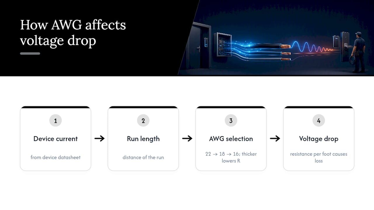
American Wire Gauge (AWG) numbers run backward from what most people expect: the smaller the number, the thicker the wire. A 12 AWG conductor carries far more current than a 22 AWG conductor, even though 22 is the larger number. That inverse relationship trips up new installers more than any other part of gauge selection.
Each step down in AWG number roughly doubles the wire’s cross-sectional area every six gauges, which is why the jump from 22 AWG to 18 AWG matters so much for current-carrying capacity, while the jump from 18 AWG to 16 AWG matters more for long-distance voltage drop than for raw ampacity. In access control work, you’re rarely dealing with the full AWG range. Most jobs live in a narrow band from 22 AWG down to 16 AWG, with 18 AWG as the workhorse for lock power and 22 AWG shielded as the default for low-current signal wiring like readers, REX sensors, and door contacts.
The gauge number also determines the conductor’s resistance per foot, which is the figure that feeds directly into your voltage-drop calculation. A thicker conductor has lower resistance, which means less voltage lost over distance for the same current. That’s the entire reason gauge selection and distance are inseparable decisions, not two separate steps you can handle independently. Buying the correct AWG without checking it against your specific run length is close to a coin flip, and buying based on distance alone without checking current draw against the device datasheet is the other half of that same mistake.
Why Undersized Wire Is a Fire and Overheating Risk
Undersized conductors carrying more current than their gauge safely supports generate heat, and that heat has nowhere to go inside a wall cavity or conduit run. This is the safety reasoning behind NEC ampacity tables, and it applies just as much to a 24V access control circuit as it does to line-voltage wiring, even though the currents involved are much smaller.
A lock circuit that’s been sized correctly on paper can still overheat in practice if a technician later adds a second device to the same run without recalculating total current draw. That’s a common failure mode on retrofits, where a REX sensor or an auxiliary relay gets tapped into an existing power run because it’s convenient, not because anyone checked whether the conductor and its overcurrent protection can handle the added load.
Fuse and circuit breaker sizing has to match the conductor, not just the device. A power supply’s output fuse should be rated to protect the smallest gauge wire on that circuit, not the largest, since the thinnest conductor in the chain is the one that will overheat first under a fault condition. This is one of the more frequently missed items on inspection, and it’s why documenting conductor gauge on as-built drawings matters just as much for safety review as it does for future service calls.
Stranded pure copper conductors also matter here. Copper-clad aluminum has higher resistance per foot than solid copper, which means it runs hotter carrying the same current, and it’s more prone to failure at termination points where repeated flexing or vibration can crack the aluminum core over time.
How Temperature, Humidity, and Exposure Change Your Gauge Choice
Conductor resistance rises with temperature, which means a wire run through a hot mechanical room or along a sun-exposed exterior wall carries less usable current capacity than the same gauge run through a climate-controlled office ceiling. Installers who size a run using room-temperature assumptions and then route it through a rooftop conduit or a boiler room are quietly eating into their voltage-drop margin before the system is even turned on.
Humidity and moisture exposure raise a different concern: corrosion at terminations and connector points, which increases resistance at the exact spots where voltage drop is hardest to diagnose later. Exterior gate access points, parking structure entries, and loading dock doors are the usual trouble spots, and they call for gel-filled or moisture-sealed connectors rather than standard wire nuts or crimp terminals, regardless of the gauge chosen.
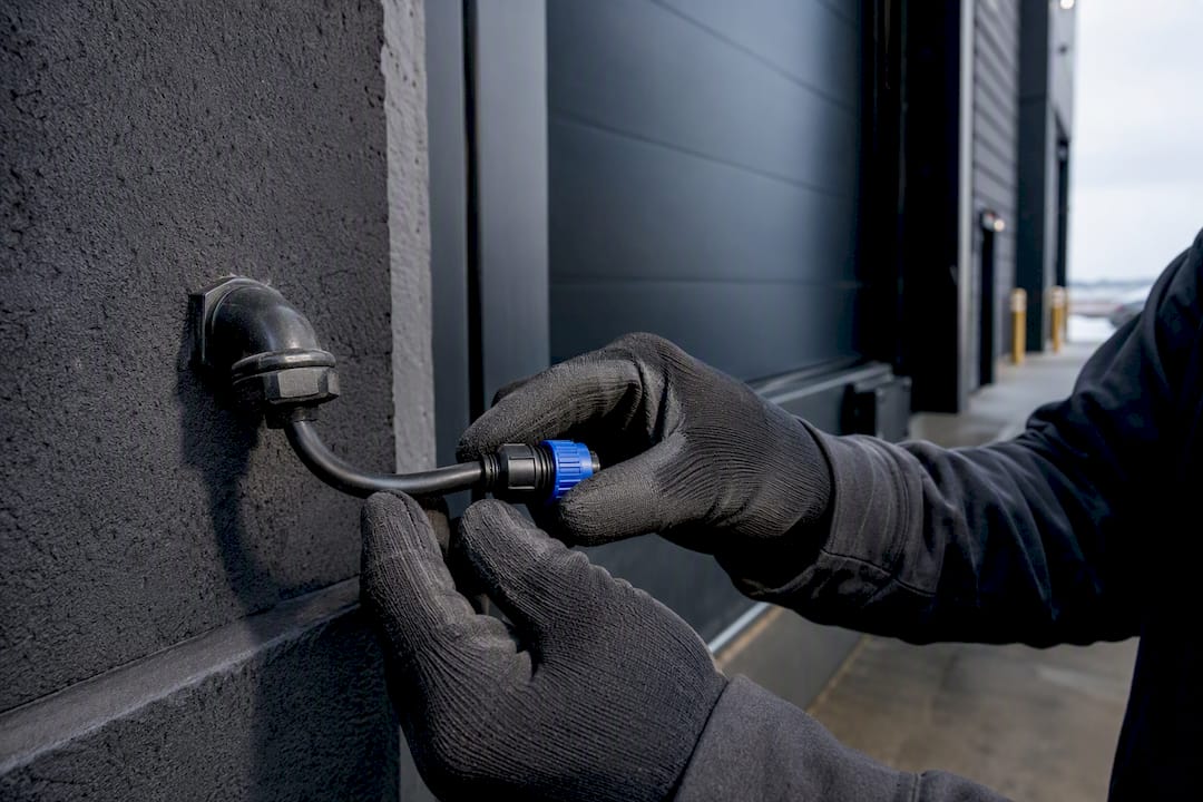
Direct sun exposure and wide temperature swings also affect the cable jacket itself. A jacket rated for indoor plenum use will degrade faster outdoors, and that degradation eventually exposes conductors to the elements even when the gauge itself was sized correctly. For any run crossing an unconditioned space, exterior wall, or rooftop, plan for a slightly heavier gauge than the indoor calculation alone would suggest, since the added margin offsets both the resistance increase from heat and the practical reality that these runs are harder to access for a future repair.
What Wire Gauge and Cable Type Actually Cost
Gauge selection affects material cost far less than most first-time installers assume, and it affects labor cost far more. The price difference between 22 AWG and 18 AWG composite cable per foot is small, and on a typical commercial door count, upsizing an entire job by one gauge rarely moves the material budget by more than a few percentage points.
The real cost driver is what happens when a run is undersized and fails inspection or fails in the field after handoff. A re-pull means opening finished walls, rescheduling building access, and absorbing labor twice for a run that should have been right the first time. That’s the calculation that should drive gauge decisions, not the per-foot price difference on the spool.
Composite cable typically costs less overall than pulling separate individual conductors for power, data, and REX signaling, since it reduces the number of pulls and the conduit fill required. But it’s not always the cheaper choice. Once a lock’s current draw exceeds what the composite’s bundled power conductor safely carries, splitting off a separate heavier power run costs more upfront than composite alone, yet it’s still cheaper than an undersized composite run that has to be abandoned and re-pulled later. Shielded 22 AWG for readers costs modestly more than unshielded equivalents, and that premium is worth paying anywhere EMI sources like elevators or HVAC equipment share the same pathway.
The Editorial Take: Where Installers Get Wire Gauge Wrong
Most gauge mistakes on a jobsite aren’t caused by ignorance of AWG tables. They’re caused by treating gauge selection as a one-time lookup instead of a per-run calculation that has to account for actual distance, actual current, and the specific device installed, not a generic assumption carried over from the last job.
The conventional advice to “just use 18 for locks and 22 for readers” isn’t wrong, but it’s incomplete, and treating it as a universal default is how long runs and high-current maglocks end up undersized. The distance check in step 2 of the selection workflow gets skipped more often than any other part of the process, mostly because it requires walking the actual conduit path rather than eyeballing a floor plan.
If there’s one place to prioritize effort, it’s the voltage-drop calculation on every run over roughly 100 feet, not just the ones that feel long. A run that looks short on a floor plan can measure much longer once it follows conduit through walls, above ceilings, and around structural obstructions, and that gap is where undersized wire quietly turns into a service call six months after handoff.
— Ken
Get Access Control Wiring Done Right the First Time
There are alternatives to guessing at gauge charts or hiring a low-voltage crew that treats access control cabling as an afterthought to their CCTV work. Some companies design and install access control cabling sized correctly on the first pull, coordinated with the AHJ before conduit installation, and documented with as-built records that facilities teams can use.

A typical engagement starts with a site survey to measure real conduit paths and confirm device current draw against actual datasheets, not assumptions. Then, the process includes composite or custom cable builds, field testing under load, and delivering documented as-built drawings that make future service calls faster instead of guesswork. That combination is what keeps callbacks down and passes inspection the first time. If you’re planning a new door count or troubleshooting a system with intermittent lock failures, explore Cables and Chips’ access control installation services in New York City and get a site survey scheduled.
Sources
- Choosing the right power supply to avoid access control issues
- Security cable voltage drop: explanation and diagnostics
- Recommended wires for access controllers (Verkada)
- Powering and wiring electrified door hardware
FAQ
How Do I Tell If My Wire Is 12 or 14 Gauge?
Check the jacket printing, which almost always states the AWG size directly, or measure the bare conductor’s diameter with a wire gauge tool since 12 AWG measures thicker than higher AWG numbers despite the lower number indicating the larger wire.
What Cable Is Used for Access Control?
Most installs use composite access control cable that bundles 18 AWG stranded copper for lock power with 22 AWG shielded conductors for reader and REX signaling, while IP and PoE readers run on CAT6.
What Type of Cable Works Best for Readers?
Wiegand and RS-485 readers need 22 AWG shielded, multi-conductor cable to protect low-current signals from electrical interference, while IP-based readers should run on CAT6 to handle both data and PoE power.
How Is Access Control Wired?
Access control wiring runs power from a fused supply to locks, signal wiring from readers and REX sensors back to the controller, and data connections from the controller to the access control panel or network, with every run sized by total current, distance, and target voltage drop. Cables and Chips handles this design and installation work for commercial facilities that need it done to code the first time.