
25.5W Covers Most APs, PoE Rules Installers Use to Avoid Callbacks
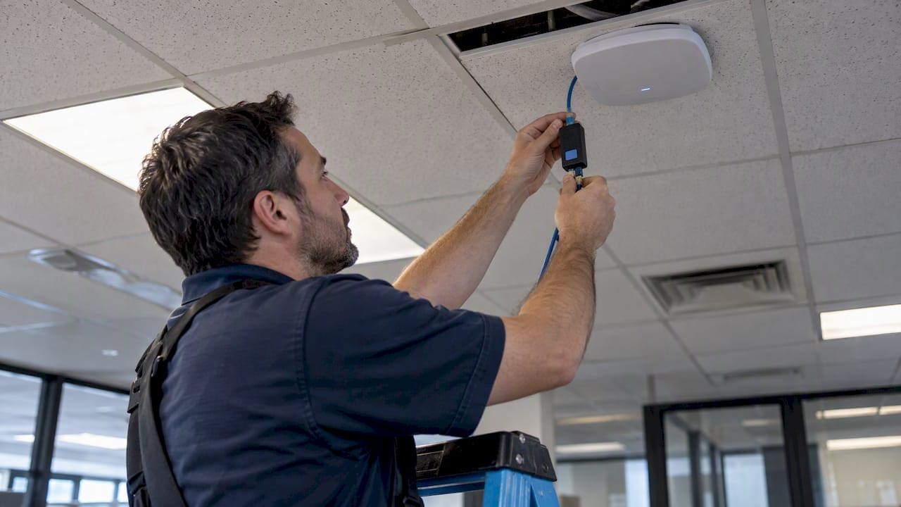
Most current access points run reliably on PoE+ (802.3at), which delivers roughly 25.5W of usable power to the device. Access points with tri‑radio chipsets, USB‑powered IoT modules, or multi‑gig uplinks often require 802.3bt, which provides higher power levels suitable for these features. Before buying switches or injectors, confirm the negotiated PD class and check whether the controller reports a “Low Power” or “Medium Power” state, since that flag reveals an underpowered deployment faster than any datasheet.
TL;DR:
- 802.3af delivers about 13 watts, while 802.3bt Type 3 and Type 4 provide about 51 and 71 watts, respectively, for higher power devices.
- Check each access point’s features: some WiFi 7 models need Type 4 for full tri radio use, while lower tier models run on PoE+.
- Sum the maximum rated draw across all access points, add a 20% buffer, and compare the total with the switch’s chassis power supply rating.
- When power is insufficient, firmware may disable a radio or USB port, or reduce a multi gig uplink to standard gigabit speed.
- For long Type 4 runs, use Cat6A cable with 22 AWG conductors and keep Ethernet cabling within the 100 meter distance limit.
PoE Standards and PD Class Semantics Explained
The IEEE 802.3 family defines three practical tiers for powering access points, and each tier changes what the AP can actually do once it boots.
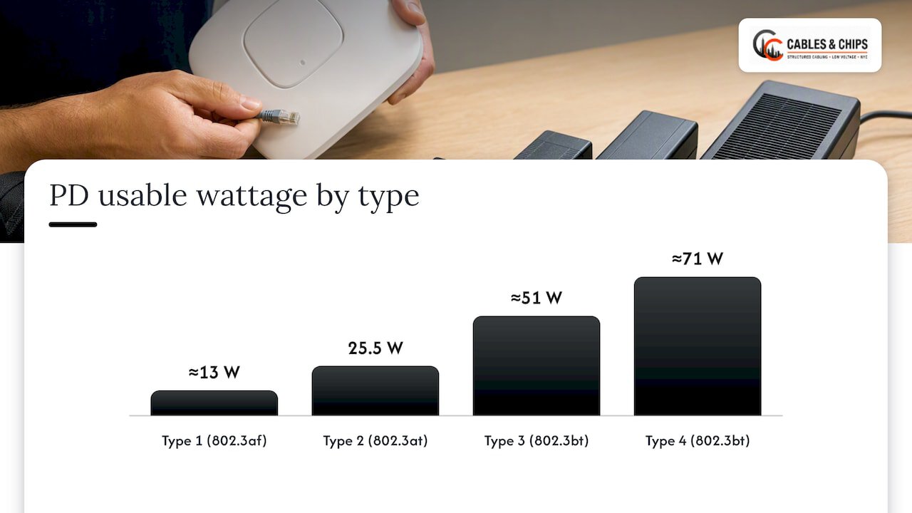
802.3af (Type 1) was built for basic devices and tops out at a modest wattage, too low for most modern dual‑radio APs. 802.3at (Type 2, commonly called PoE+) doubled that ceiling and became the baseline for enterprise Wi‑Fi 5 and Wi‑Fi 6 deployments. 802.3bt (Type 3 and Type 4) added four‑pair power delivery, pushing usable wattage high enough for tri‑radio Wi‑Fi 6E and Wi‑Fi 7 hardware, USB-powered sensors, and multi‑gigabit uplinks.
Vendor technical documentation lists PD usable wattage by type as roughly:
- Type 1 (802.3af): about 13W delivered to the device
- Type 2 (802.3at / PoE+): about 25.5W delivered to the device
- Type 3 (802.3bt): about 51W delivered to the device
- Type 4 (802.3bt): about 71W delivered to the device
The PSE (the switch or injector) and the PD (the access point) negotiate a class from 0 through 8 before any significant current flows. That negotiation determines how much power the switch reserves, which is why two APs on the same switch port type can still behave differently if their class negotiation fails or defaults low.
How AP Features Map to Power Needs
A power table only matters once you connect it to what the AP is actually doing. Radios, USB ports, and secondary Ethernet outputs all draw from the same power budget, and stacking features is what pushes a device from PoE+ into 802.3bt territory.
- Single or dual‑radio Wi‑Fi 5/6 APs typically sit comfortably within PoE+ (802.3at), drawing in the mid‑teens to low‑twenties of watts.
- Tri‑radio Wi‑Fi 6E and Wi‑Fi 7 access points often require 802.3bt, since the added 6 GHz or additional spatial streams increase baseline draw.
- APs with a PoE pass‑through port for a secondary device (a camera or a sensor) add that device’s draw on top of the AP’s own consumption.
- Multi‑gigabit (mGig) uplink ports draw more power at the PHY layer than standard gigabit ports, especially at 2.5G or higher negotiated speeds.
- USB‑powered accessories, such as IoT radios or Bluetooth beacons built into the AP housing, pull additional watts that vendor spec sheets list separately.
Cisco’s own integration documentation is explicit on this point: certain Wi‑Fi 7 platforms need 802.3bt Type 4 power for full tri‑radio operation, while a lower-tier model in the same family runs fine on standard 802.3at. The lesson generalizes well beyond one vendor: never assume a “Wi‑Fi 7 AP” automatically means “needs 90W.” Check the specific model’s feature set first.
What Reduced Functionality Looks Like on an Underpowered AP
Access points rarely fail outright when underpowered. Instead, firmware quietly disables features to stay within the power budget the switch actually grants, which makes diagnosis harder if you are not looking for it.
Common symptoms include a disabled 5 GHz or 6 GHz radio, a USB port that never initializes, or an mGig uplink that negotiates down to standard gigabit speed. Cisco’s own support documentation for Catalyst and Aironet platforms lists exact reduced-function outcomes per model when an AP receives only 15W or 30W instead of its full rated power, and the pattern repeats across vendors: whichever radio or port draws the most power gets cut first.
Wireless controllers typically surface this as a “Low Power” or “Medium Power” state in the AP’s management page rather than throwing a hard error. That distinction is worth training junior technicians on, since a client complaining about weak 6 GHz coverage might actually have a power problem, not an RF problem.
- Check the AP’s detail page in the controller for any power-state warning before troubleshooting RF.
- Review firmware release notes, since some power behaviors change between versions on the same hardware.
- Confirm the negotiated PD class in switch logs rather than assuming the cable run determines power automatically.
Non‑standard implementations complicate this further. Some legacy “Universal PoE” or proprietary high‑power modes are not fully compatible with 802.3bt negotiation, which can cause an AP to power up but never reach full wattage even on a PSE rated for it.
Switch Power Budgeting and the PSE Negotiation Handshake
Every PoE switch has a total power supply budget that is almost always smaller than the sum of every port running at maximum class simultaneously. Planning around per‑port capability alone, without checking the chassis‑wide PSU rating, is one of the most common causes of intermittent AP power loss during a refresh.
- List every AP’s maximum PD wattage from its datasheet, not its “typical” or “average” figure.
- Sum those maximums for every port on the switch or stack.
- Add a 20% buffer to that sum to account for inrush current and future device additions, a practice reflected in our PoE power budget guide.
- Compare the buffered total against the switch’s rated total PSU wattage, not just its per‑port maximum.
- If the buffered total exceeds the PSU rating, redistribute APs across additional switches or add a redundant power supply.
Pro Tip: Keep LLDP or CDP enabled on every switch port serving a PoE device; disabling it to “simplify” a config is a common source of APs stuck negotiating the wrong power class.
The PSE assigns power based on the class the PD requests during the LLDP or CDP handshake, not on instantaneous draw, so a misconfigured negotiation can cap an AP’s power well below what the switch could otherwise supply. Midspan injectors introduce their own risk here: a passive injector paired with a managed PoE+ switch port can create a voltage mismatch, and unsupported proprietary PoE schemes sometimes skip the standard classification step entirely.
Cabling, Voltage Drop, and Port Speed at Longer Runs
Cable choice affects how much of the power leaving the switch actually reaches the AP, and the difference becomes significant on longer runs or higher‑wattage classes. A reasonable installer rule of thumb is to keep voltage drop within a 3 to 5V margin under full load, as detailed in our voltage drop guide, since anything beyond that risks the AP undershooting its negotiated class.
For 802.3bt Type 4 deployments (up to 71W usable), Cat6A with 22 AWG conductors is the safer baseline over long runs, because thinner conductors lose more voltage to resistance at higher current draw, as outlined in our Cat6A PoE guidance.
- The 100-meter Ethernet distance limit still applies to PoE runs; exceeding it risks both data errors and power loss, a failure mode covered in our Cat5e distance analysis.
- Runs approaching that limit, or APs requiring Type 3 or Type 4 power, benefit from Cat6A over Cat5e or standard Cat6.
- Outdoor or high‑EMI environments call for shielded cable to protect both data integrity and stable power negotiation.
A subtler trap involves injectors rated for 802.3bt power but not for 10 Gbps data. Technical notes on the standard warn that some older 802.3bt injectors cap throughput well below 10G, which silently throttles a multi‑gig AP even though power delivery looks correct. Always match the injector’s data-rate rating to the AP’s uplink speed, not just its power class.
Practical Deployment Checklist and Verification Steps
A short, repeatable checklist prevents most PoE callbacks before they happen.
- Pre-install: Pull the AP’s datasheet, confirm switch or injector PoE class support, verify cable category against run length, and run the power budget math with a 20% buffer.
- Install: Test and certify the cable run, connect the AP, and confirm the controller shows full negotiated class rather than a reduced power state.
- Functional check: Verify every radio is active, USB ports initialize, and mGig uplinks negotiate at their rated speed.
- Post-install: Run a traffic test under load, then document power draw per port alongside the cable label for future maintenance, a step detailed further in our access point cabling plan.
Installer Tips to Avoid PoE Callbacks
Field experience across commercial deployments points to a few repeatable rules. Mixing passive injectors with managed PoE+ switches, running long cable without a voltage-drop calculation, and skipping a load test before signoff account for most of the PoE issues technicians get called back to fix. Documenting power assignments per port at install time saves hours during later troubleshooting.
When 802.3bt Makes Sense for New AP Rollouts
Our take: 802.3bt earns its cost on Wi‑Fi 7 or tri‑radio deployments with USB‑powered accessories or multi‑gig uplinks, not as a default for every refresh. For standard dual‑radio replacements, staying on PoE+ and staging 802.3bt switches in for specific zones controls cost without limiting future flexibility.
— Ken
Planning PoE and Cabling for Your Access Point Rollout
Getting AP power right on paper is only half the job. The other half is a cabling plan that delivers clean, tested connections to every closet and ceiling drop without surprises at turn-up.

We design and install structured cabling for commercial AP deployments across New York City, including WiFi Design tailored to PoE power budgets, Structured CAT6 Cabling sized for high‑wattage runs, and Cable Testing & Certification to confirm every port performs as specified before signoff. We also handle MDF / IDF Cleanup so power budgeting and port documentation stay accurate as a network grows. With more than 40 years of experience in commercial low voltage work, we build network infrastructure that is clean, documented, and ready to support the APs running on it. For a broader look at power planning around electrical capacity, Holland Electric’s guide to network expansion covers related infrastructure considerations for commercial properties.
Request a no-obligation site survey through our services page and we will map your AP power and cabling requirements before you commit to hardware.
FAQ
What are the PoE requirements for the Ubiquiti AP?
Ubiquiti UniFi access points generally accept a 44 to 57V DC input range, with maximum consumption varying by model. The U6‑LR maximum consumption is about 18.5 watts, so it runs comfortably on standard PoE or PoE+ depending on the switch or injector used.
Is PoE+ 24 or 48V?
PoE+ (802.3at) operates with variable voltage depending on cable length and load. Vendor documentation on PoE voltage ranges confirms voltage varies across standard 802.3at implementations.
How many access points for 10,000 square feet?
The right AP count depends heavily on wall construction, ceiling height, and expected device density rather than square footage alone, so there is no single standard figure to cite. A proper site survey, rather than a square-footage formula, remains the reliable way to plan AP placement and the cabling runs that support it.
What are the PoE requirements for the AP47?
Power requirements vary by exact model line and firmware revision, so always confirm the specific datasheet for the model in question rather than relying on a general figure. Checking the controller for a “Low Power” or “Medium Power” state after install is the fastest way to confirm whether that specific unit is receiving full power.