

A wifi access point cabling plan is the structured layout of Ethernet cabling, power delivery, and termination points that connects wireless access points to your network infrastructure. Without a documented plan, commercial WiFi deployments produce dead zones, overloaded switches, and cabling that nobody can service two years later. The industry term for this work is structured cabling, and it governs everything from cable type selection to patch panel labeling. Getting it right before installation starts is the difference between a network that performs and one that gets rewired.
What does a wifi access point cabling plan include?
A complete plan covers AP quantity, physical placement, cable routing paths, cable type, power delivery method, and termination points at both the AP end and the network closet. Each of these decisions affects the others. Choose the wrong cable type and your PoE budget falls short. Skip the routing plan and your installers pull cable through conduit that is already at fill capacity. The plan is the document that prevents those problems before they cost money.
Structured cabling for WiFi APs follows ANSI/TIA-568 standards, which define cable categories, connector types, and maximum run lengths. These standards exist because commercial networks are maintained by multiple teams over many years. A documented, standards-compliant installation is one that any qualified technician can pick up and service without guessing.
How many access points does a commercial space need?
The baseline planning metric for commercial office spaces is one AP per 2,500 square feet with open ceilings. That number shifts based on several factors that every IT manager needs to account for before pulling cable.
Key factors that increase AP density:
- High device density. Conference rooms, trading floors, and open-plan offices with 50+ devices per zone need tighter AP spacing.
- Obstructions. Concrete walls, metal partitions, and glass-walled offices all attenuate signal. Each obstruction effectively shrinks the coverage radius of an AP.
- Application type. Video conferencing and VoIP traffic require lower latency and higher throughput per user, which means more APs handling fewer clients each.
- Ceiling height. Warehouses and atriums with ceilings above 20 feet change the signal propagation pattern significantly.
Ceiling mounting is the standard for commercial deployments. It provides the widest coverage pattern and keeps APs out of reach of accidental interference. Wall mounting works in corridors and stairwells where ceiling access is impractical.
Site surveys and coverage mapping before cable installation are the most effective way to avoid costly rewiring after the fact. A proper RF site survey uses tools like Ekahau or NetSpot to model signal propagation against the actual floor plan. That data drives AP placement decisions with real numbers rather than guesswork.
Pro Tip: Run your site survey with the space furnished and occupied if possible. Empty rooms behave very differently from rooms full of people, furniture, and equipment.

What cabling standards apply to WiFi AP installations?
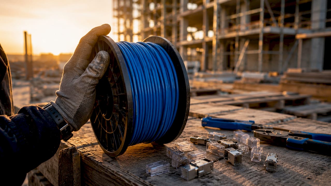
Cat6A is the required cable for WiFi 6 and WiFi 7 access points running on 802.3bt PoE. The reason is thermal, not just electrical. When cables are bundled in ceiling trays, they generate heat. Cat6A’s larger conductors reduce resistance and dissipate heat more effectively than Cat6 or Cat5e, which is critical when you are delivering 51W or more per port.
| PoE Standard | Max Power at Port | Minimum Cable | Typical AP Use Case |
|---|---|---|---|
| 802.3af | 12.95W | Cat5e | Basic 802.11ac APs |
| 802.3at | 25.5W | Cat5e/Cat6 | Mid-range WiFi 6 APs |
| 802.3bt Type 3 | ~51W | Cat6A | High-density WiFi 6 APs |
| 802.3bt Type 4 | ~71.3W | Cat6A | WiFi 7 APs, multi-radio APs |
PoE power standards vary significantly across these four tiers. Selecting the wrong cable for a high-power deployment does not just reduce performance. It creates a fire risk in dense cable bundles over time.
Solid-core cable is the correct choice for permanent runs from the network closet to the AP location. Stranded cable is used only for patch cords at each end. Stranded cable is more flexible but has higher resistance over long runs, which degrades both data and power delivery. Every permanent horizontal run should be solid-core, terminated to a keystone jack or patch panel with the appropriate tooling.
Pro Tip: Check the Cat6A specifications for your specific AP model before ordering cable. Some WiFi 7 APs with multi-gig uplinks require 2.5G or 5G switch ports, and your patch panel needs to match.
How to execute a professional WiFi AP cabling installation
The installation process follows a specific sequence. Skipping steps creates problems that are expensive to fix after ceilings are closed.
- Pull a dedicated home run cable for each AP. Each AP requires its own cable run back to the patch panel. Daisy-chaining APs through a single cable run is not supported and creates a single point of failure for multiple APs.
- Install low-voltage mounting rings at each AP location. Low-voltage mounting rings provide a clean termination point in the ceiling and protect the cable end. They also allow future AP repositioning without pulling new cable.
- Maintain a service loop. Leave 3–5 feet of cable coiled in the ceiling above each AP location. This slack allows repositioning the AP, replacing a damaged connector, or re-terminating without pulling a new run.
- Separate from electrical conduit. Keep data cable at least 12 inches from electrical conduit carrying 120V or higher. Electromagnetic interference from power lines degrades signal quality, particularly at higher data rates.
- Respect cable tray fill limits. Overfilled trays compress cables, increase heat buildup, and make future pulls difficult. ANSI/TIA-569 defines fill ratios for cable trays. Stay within them.
- Test every run before deploying APs. Use a cable certifier such as a Fluke Networks DSX-600 to verify continuity, wire map, insertion loss, and PoE performance. A run that fails certification will cause intermittent problems that are very hard to diagnose after the AP is mounted.
Common pitfalls to avoid:
- Exceeding the 100-meter maximum run length for Cat6A horizontal cabling
- Kinking cable around tight corners, which damages the internal pairs and causes crosstalk
- Skipping labeling at both ends of every run, which makes troubleshooting take hours instead of minutes
- Terminating to a patch panel without documenting the port-to-AP mapping in a cable schedule
For open office cabling layouts, the patch panel organization at the IDF or MDF is as important as the cable runs themselves. A well-organized network closet with labeled ports and documented cable schedules cuts troubleshooting time significantly.
Pro Tip: Use a structured cable schedule spreadsheet that maps each AP’s physical location, ceiling drop number, patch panel port, and switch port. Update it every time you move or add an AP.
Copper vs. fiber: which cabling solution fits your deployment?
The choice between copper Ethernet and fiber optic cabling is not either/or in most commercial deployments. Fiber backbone with copper final runs is the standard design for larger or high-density networks. Fiber connects the main distribution frame (MDF) to intermediate distribution frames (IDFs) on each floor. Copper Cat6A carries the signal from the IDF to each individual AP.
| Factor | Copper Cat6A | Fiber Optic |
|---|---|---|
| Maximum distance | 100 meters | 300m+ (OM4 multimode) |
| PoE support | Yes | No |
| Cost per run | Lower | Higher |
| Installation complexity | Standard | Requires fusion splicing or connectorization |
| Typical role | AP final drop | Backbone between closets |
Fiber cannot deliver PoE power, which is why copper remains the final connection to every AP. The AP needs both data and power over the same cable. That requirement makes Cat6A the only practical choice for the last 100 meters.
For buildings with multiple floors or long horizontal distances, fiber optic cabling advantages include immunity to electromagnetic interference and the ability to carry 10G or 40G between closets without signal degradation. A hybrid design gives you the distance and bandwidth of fiber on the backbone with the simplicity and PoE capability of copper at the edge.
When planning a multi-floor deployment, coordinate with your building cabling infrastructure team early. Riser conduit space, fire-stop penetrations, and MDF/IDF locations all affect where fiber can run and how much it costs.
Key takeaways
A complete wifi access point cabling plan requires documented AP placement, Cat6A cabling for PoE-powered APs, home run topology to the patch panel, and certified testing before deployment.
| Point | Details |
|---|---|
| AP density baseline | Plan one AP per 2,500 sq ft in commercial spaces, then adjust for obstructions and device density. |
| Cat6A is required | Use Cat6A for any AP running 802.3bt PoE to prevent thermal degradation and maintain data integrity. |
| Home run topology | Run a dedicated cable from each AP back to the patch panel. Never daisy-chain AP drops. |
| Test before deploying | Certify every run with a cable certifier before mounting APs to catch faults early. |
| Hybrid fiber and copper | Use fiber for backbone runs between closets and Cat6A copper for the final drop to each AP. |
What I’ve learned planning AP cabling in commercial buildings
The mistake I see most often is treating the cabling plan as an afterthought. Teams select their AP hardware, get excited about the wireless controller, and then hand a vague scope to an installer. The result is a mix of Cat5e and Cat6 runs, no service loops, and a patch panel that looks like a bowl of spaghetti six months later.
The projects that go well start with a proper site survey before a single cable is pulled. That survey drives the AP count, the cable routing plan, and the IDF layout. When construction teams get the cabling plan early, they can coordinate conduit placement and ceiling access before drywall goes up. That coordination saves real money.
Cat6A and 802.3bt infrastructure is worth the upfront cost. WiFi 7 APs are already shipping with multi-radio configurations that draw close to 71W. If you install Cat6 today to save a few dollars per run, you will be pulling new cable in three years. The scalable cabling infrastructure approach costs more at installation and far less over the life of the network.
The other thing I tell every facilities manager: label everything twice. Label the cable at the AP end and at the patch panel. Put the AP location, the panel port number, and the switch port on both labels. When something fails at 2 a.m., that documentation is worth more than any piece of hardware in the closet.
Your network is only as strong as the infrastructure behind it.
— Ken
Plan your next WiFi deployment with Cables
Cables has spent more than 40 years designing and installing structured cabling for commercial WiFi deployments across New York City. From site surveys and AP placement planning to Cat6A installation, patch panel termination, and certified cable testing, the team at Cables handles every phase of the project. Whether you are wiring a single floor or a multi-building campus, the work is documented, tested, and built to last. Explore the full structured cabling system components guide to understand what a complete installation includes, or review Cat6A installation services for commercial WiFi deployments in NYC. Contact Cables at 20 Vesey Street, Lower Manhattan, to schedule a site survey.
FAQ
What cable type is required for WiFi 6 and WiFi 7 access points?
Cat6A is required for WiFi 6 and WiFi 7 APs running on 802.3bt PoE, which delivers up to 71.3W per port. Cat6A’s larger conductors handle the thermal load that high-power PoE generates in bundled ceiling runs.
How far can a Cat6A cable run to an access point?
The maximum horizontal run for Cat6A is 100 meters from the patch panel to the AP. Runs beyond this limit require a fiber backbone with a media converter or an additional IDF location closer to the APs.
What is home run topology in AP cabling?
Home run topology means each AP has its own dedicated cable run back to the patch panel, with no shared or daisy-chained connections. This design isolates faults to a single AP and makes troubleshooting and upgrades straightforward.
Do I need a site survey before planning AP cabling?
A formal site survey is the most reliable way to determine AP quantity and placement before cable is pulled. Skipping the survey risks poor coverage, over-provisioned hardware, or costly rewiring after installation.
Can fiber optic cable power a WiFi access point?
Fiber cannot deliver PoE power. Access points require copper Ethernet cable, specifically Cat6A for high-power deployments, because PoE uses the copper conductors to carry both data and electrical power to the AP simultaneously.