
Cat6A 22AWG PoE Lighting Cabling for Installers: Stop 100m Power Loss

Power over Ethernet lighting sends both electrical power and network data through a single twisted-pair cable, replacing separate AC wiring with a structured cabling run. The practical rule for installers is simple: Cat5e is the minimum acceptable cable, but Cat6A with 22AWG conductors is the recommended choice for reliable, high-power installations under the 802.3bt standard. Every run is capped at 100 meters, and no installation should go live without a documented power budget and a field test.
TL;DR:
- Cable selection should prioritize Cat6A with 22AWG conductors for high-power PoE lighting installations, especially near the 90 watt Type 4 standard.
- Power budgeting must account for total fixture load, cable loss, and the switch’s overall power capacity, not just per-port ratings.
- Complete testing with PoE-specific certifiers and field load tests is essential to identify resistance unbalance and ensure reliable long-term operation.
- Bundled cables require LP-certified rated conductors and proper grounding to manage heat buildup, with stricter limits on bundle size in compliance with electrical codes.
- Using proper conductor gauge, thorough field testing, and accurate documentation reduce failure risks and improve compliance in PoE lighting projects.
What PoE lighting is and why organizations choose it
PoE lighting fixtures draw their power and their control signal from the same Ethernet cable, which removes the need for a licensed electrician to run separate AC circuits to every fixture. The same cable that powers the light also carries data to occupancy sensors, daylight harvesting controls, and building management systems, forming a key component of energy-efficient smart buildings as detailed in this energy efficiency guide, so a lighting network becomes part of the IT infrastructure rather than a separate trade. That integration is a major driver behind the shift: transitioning to PoE lighting is as much about controls and data as it is about power, and a well-built cabling plant is what unlocks those benefits.
Organizations deploying PoE lighting typically see these advantages:
- Lower installation cost in retrofits, since low-voltage cable runs are faster to pull than conduit and AC wiring.
- Centralized control through a single network, making it simple to schedule, dim, or zone fixtures from one interface.
- Easier integration with occupancy sensors and daylight harvesting systems for automated energy savings.
- Simplified moves and changes, since relocating a fixture means moving a cable, not rerouting a circuit.
Open offices, warehouse retrofits, and buildings pursuing smart lighting controls are the most common adopters.
PoE standards and power types relevant to lighting
PoE lighting runs on the IEEE 802.3 family of standards, and each generation raised the available power. The original 802.3af standard delivered modest power suited to small sensors and phones. The 802.3at (PoE+) standard pushed that higher for access points and small fixtures. The real shift for lighting came with 802.3bt, which uses all four pairs of the cable instead of two.
Under 802.3bt, Type 4 delivers power at levels suitable for high-power applications, and Type 3 offers moderate power delivery, with the actual wattage varying by installation and cable quality. That 15 to 20 percent gap between source and device power is cable loss, and it is the number that makes cable selection a real engineering decision rather than a formality.
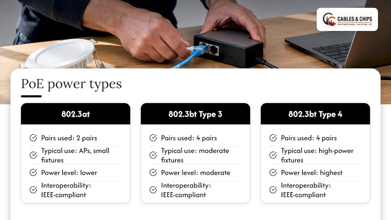
Every PoE switch port negotiates power class with the connected fixture before full power flows, which is why a lighting project needs a switch with enough total power budget for every fixture running at once, not just enough per port. Some manufacturers offer proprietary high-power extensions beyond the IEEE standard, but a lighting design built strictly on 802.3bt classes stays interoperable across vendors.
Cabling choices: category, conductor gauge, and certification
Cable selection is where most PoE lighting problems start, and where they are cheapest to prevent. Industry guidance for PoE installations sets Cat5e as the floor and Cat6A as the preferred category, particularly for any fixture pulling close to the 90 watt ceiling of Type 4 power. Our own field experience with Cat5e in high-power PoE runs backs this up: thinner conductors and lower-grade shielding start losing margin well before they reach the full 100 meter channel limit.
Conductor gauge matters as much as category:
- 22AWG conductors deliver the best efficiency for Type 3 and Type 4 power and are worth specifying on any new lighting cable run.
- 23AWG is a reasonable compromise on cost and flexibility for mid-power fixtures.
- 24AWG, common in standard patch cords, is the least efficient option and should be avoided on permanent PoE lighting links.
Pro Tip: Match your patch cords to your permanent link category and AWG. A Cat6A permanent run paired with thin 24AWG patch cords quietly erases the headroom you built into the cable plant.
UL’s Limited Power (LP) certification is worth specifying for bundled runs, since it signals the cable has been rated for the heat generated when many PoE conductors run together. Shielded cable is a sensible choice in environments with heavy electrical interference, such as near fluorescent ballasts or motor equipment, though it adds cost and requires proper grounding to be effective. For a longer look at category trade-offs, our guide to matching PoE standards with cabling walks through the decision in more detail.
Installation practicals: length, power budget, and code limits
The 100 meter channel limit set by IEEE is a hard ceiling, not a target, and it includes patch cords on both ends, not just the permanent horizontal run. Voltage drop across that distance eats into the power a fixture actually receives: as Digi-Key notes, even a cable run at the full 100 meters can drop enough voltage that a powered device fails to start up reliably if the cable loss was not accounted for in the power budget.
A basic power budget calculation for a PoE lighting project follows a few steps:
- Total the PD draw of every fixture on a switch, using the device’s actual rated wattage, not its PoE class ceiling.
- Compare that total against the switch’s total PoE power budget, not just its per-port maximum.
- Add a cable loss margin for runs approaching 100 meters, especially on 24AWG or 23AWG cable.
- Confirm the switch can sustain that load continuously, not just at startup.
Bundling many PoE cables together creates heat, and that heat matters legally as well as electrically. NEC ampacity tables limit how many PoE-powered cables can run together in a bundle based on conductor gauge and temperature rating, which is why large lighting deployments often specify LP-certified cable instead of counting bundle sizes against standard tables. For projects with critical lighting zones, redundant PSEs and a dedicated VLAN for lighting traffic keep a single switch failure or network event from taking down an entire floor.
Field testing and certification: what to test and which tools to use
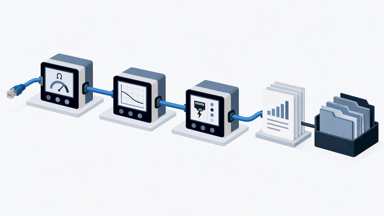
A cable plant that passes a basic wiremap test can still fail under PoE load, which is why lighting projects need PoE-specific certification, not just continuity checks. Fluke Networks’ installation guidance calls for DC resistance unbalance measurements within each pair and between pairs, along with DC loop resistance, because unbalance under power causes data errors and heat that a simple pass or fail wiremap never catches. Insertion loss and NEXT measurements remain relevant too, confirming the link supports the data side of the connection at full PoE load.
The practical toolkit for this work includes:
- A cable certifier with dedicated +PoE test limits, such as the Fluke Networks DSX CableAnalyzer, to measure resistance unbalance against pass or fail thresholds.
- A field tester like LinkIQ or MicroScanner to confirm the negotiated PoE class and real-time port voltage under an actual load.
- A PoE load test during commissioning to verify the switch delivers rated power when every fixture on that circuit is drawing current simultaneously.
Pro Tip: Run your PoE load test with every fixture on the switch powered on at once. A port that passes in isolation can still sag when the full lighting zone pulls power together.
Documented test reports matter beyond the install. Warranty claims and future troubleshooting both depend on having a baseline record of resistance, loss, and negotiated power class for every link, filed with the as-built documentation.
Planning checklist and common installation mistakes
A short checklist before pulling a single cable saves far more time than fixing a failed link after fixtures are mounted.
- Inventory every fixture’s rated wattage and total it against the switch’s PoE power budget, not just port count.
- Select Cat6A with 22AWG conductors for any run near Type 3 or Type 4 power, and Cat5e only for light, short runs.
- Terminate every connector with consistent technique, since poor seating is a leading cause of resistance unbalance.
- Certify every link with a +PoE-capable tester before fixtures go live, and keep the test reports on file.
The most common failures trace back to a handful of avoidable errors: undersized conductors on long runs, mismatched patch cords dragging down an otherwise good permanent link, and bundles left untested for heat buildup under full load. Conservative power margins, consistent use of a certifier, and complete documentation close most of that gap before it becomes a service call.
Why professional installation lowers risk on PoE lighting projects
Cables & Chips has worked as a low voltage contractor in commercial buildings for more than 40 years, installing structured Cat6 and Cat6A cabling that supports PoE lighting alongside data, WiFi, and security systems. That experience includes:
- Structured CAT6 and CAT6A installation sized correctly for PoE power classes, not just data throughput.
- Cable testing and certification with documented, PoE-rated test results for every link.
- As-built documentation and site survey reports that give building teams a clear record of what was installed and how it performs.
A professionally tested and documented cable plant gives building owners a defensible record if a fixture fails under warranty, and it removes most of the guesswork from troubleshooting later.
Where the conventional advice on PoE lighting gets it wrong
Most guidance on PoE lighting treats cable category as the whole decision: pick Cat6A, call it done. That advice undersells the two factors that actually determine whether a system holds up over years of operation, conductor gauge and field testing. A Cat6A cable with 24AWG conductors still loses more power to resistance than a Cat5e run with heavier conductors, and category alone tells an installer nothing about whether the terminations were done well.
The bigger gap is testing. Plenty of installations get wired correctly and then go live without a single PoE-specific certification test, which means the first sign of a resistance unbalance problem is a flickering fixture months after the ceiling tiles are closed up. A wiremap test proves the pairs are connected. It proves nothing about whether that link can sustain 51 watts to a device for years without data errors or excess heat.
The reader’s priority, in order, should be: specify conductor gauge before worrying about category marketing, build a real power budget instead of trusting per-port PoE class labels, and never skip the +PoE certification step. Everything else, including vendor-specific power extensions and shielding debates, matters far less than those three.
— Ken
Getting professional help with your PoE lighting cabling
PoE lighting cabling rewards the same discipline as any structured cabling project: correct category, correct gauge, and a documented test on every link. Cables & Chips provides structured CAT6 cabling, cable testing and certification, and fiber installation for commercial buildings, along with the site surveys and as-built documentation that keep a lighting project serviceable for years.

A site survey from our team typically covers:
- An inventory of fixture power requirements against available switch capacity.
- A cable path review for bundle size, length, and separation from electrical and EMI sources.
- A recommendation on category, conductor gauge, and LP certification suited to the project’s power class.
Building teams planning a PoE lighting retrofit or new build can request a no-obligation site survey through our services page to get a cabling plan matched to the actual power load, not a generic spec sheet.
FAQ
Does PoE lighting require a special cable?
PoE lighting does not require a proprietary cable, but it does require standard twisted-pair Ethernet cable rated for the power load involved. Cat5e is the accepted minimum, while Cat6A is preferred for higher-power 802.3bt installations because it runs cooler and loses less power to resistance.
What is PoE in lighting?
PoE in lighting means a fixture receives both its electrical power and its network data through a single Ethernet cable rather than separate AC wiring and a control line. This lets lighting controls, sensors, and dimming operate over the same structured cabling used for data networking.
Do I need all 8 wires for PoE lighting?
High-power PoE under the 802.3bt standard uses all four pairs, all eight conductors, to deliver Type 3 and Type 4 power levels. Older two-pair PoE under 802.3af and 802.3at only needs four conductors, so the fixture and switch’s power class determine the requirement.
What cable is suitable for PoE lighting installations?
Cat6A with 22AWG conductors is the most reliable choice for PoE lighting, particularly for fixtures drawing near the 90 watt ceiling of Type 4 power. Cat5e remains acceptable for lower-power, shorter runs, but thinner 24AWG conductors reduce the efficiency and headroom available on any high-power link.