
90 m vs. 100 m: MDF to IDF Distance Checks for IT and Facilities
Every MDF to IDF copper run is bound by the same ceiling: a 90-meter permanent link and a 100-meter total channel from end to end. High ambient heat, heavy PoE loads, or thinner conductors can shrink that ceiling further through derating, sometimes forcing a shorter run or a switch to fiber. We recommend specifying permanent-link testing and measuring the actual cable path, not the floor-plan distance, before a single cable gets pulled.
TL;DR:
- Keep combined patch cords within roughly 10 meters, and treat the tester’s 10% NVP tolerance as measurement uncertainty, not extra design capacity.
- Place IDFs near the farthest device zones; calculated permanent links above 80 to 85 meters warrant review because slack and cable sag consume remaining margin.
- Require permanent link testing and full reports covering insertion loss, loop resistance, measured length, NVP settings, and pass or fail margin before project signoff.
- Use fiber for vertical backbone runs longer than one floor; Cat6A offers lower insertion loss and better support for 10 Gigabit Ethernet and heavy PoE.
Understanding MDF and IDF and How They Connect
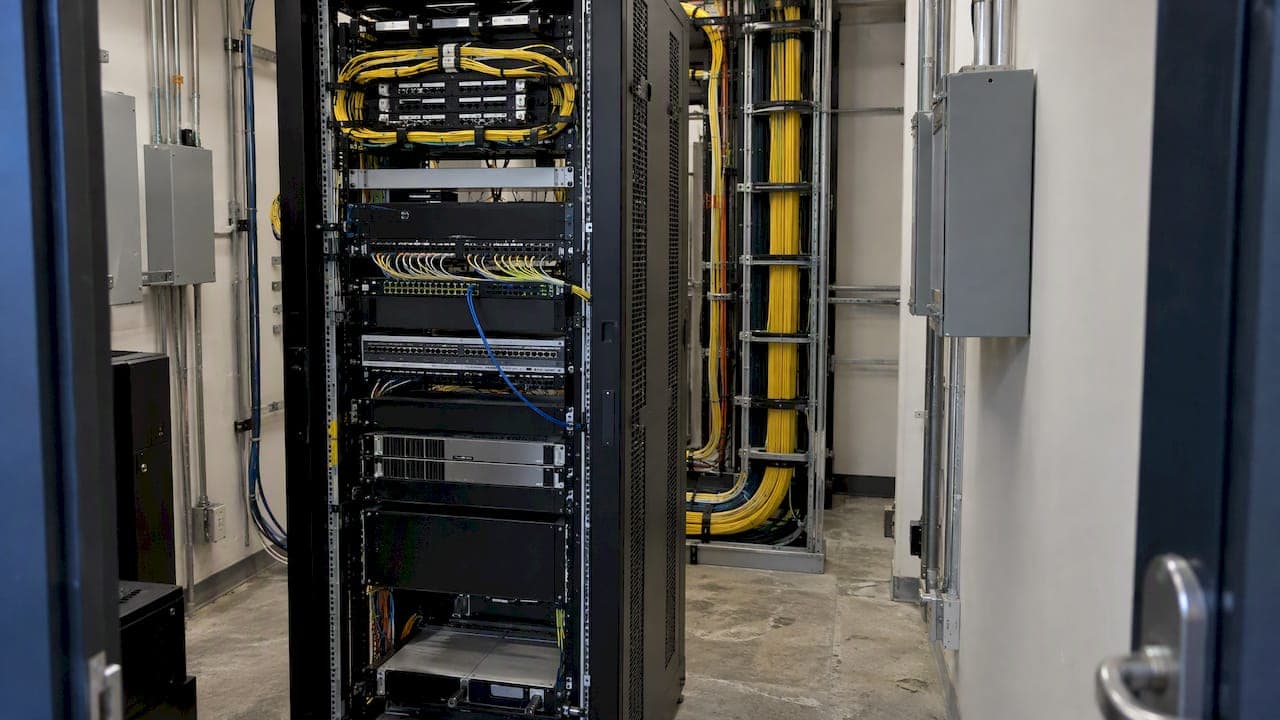
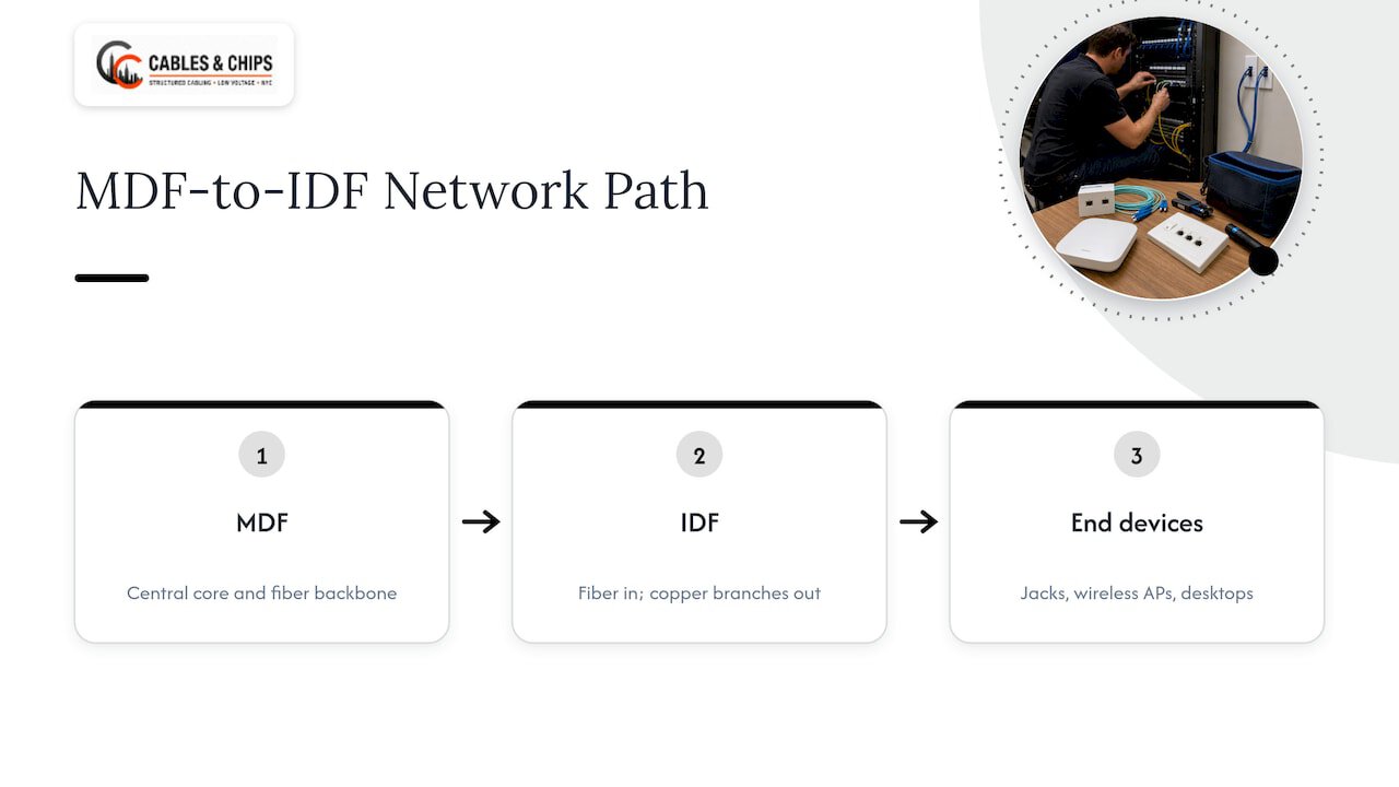
The Main Distribution Frame is the central hub of a building’s telecommunications infrastructure. It typically houses the core network switches, the demarcation point from the service provider, and the fiber backbone that feeds every other closet in the building. The Intermediate Distribution Frame is the local extension of that network, usually one per floor or coverage zone, where horizontal copper cabling branches out to wall jacks, wireless access points, and desktop connections.
The two connect through a backbone, most often fiber optic cable running vertically through risers from the MDF down to each IDF. From there, horizontal copper cabling, usually Cat6 or Cat6A, carries the signal the rest of the way to end devices. This MDF to IDF to end-device structure is the backbone of nearly every mid-size and large commercial building, and it is the same model whether the building runs a legacy telecom closet or a modern server room acting as a core distribution point.
Typical equipment in an MDF includes core switches, routers, the main patch panels, and often the building’s internet demarcation hardware. An IDF usually holds floor switches, patch panels for that zone’s horizontal runs, and sometimes local UPS units. Some larger deployments add a Building Distribution Frame between the MDF and multiple IDFs, or organize rack layouts around top-of-rack and end-of-row switching, but the underlying logic stays the same: keep the backbone centralized and keep horizontal runs short.
Short horizontal runs matter because Ethernet signal quality degrades with distance. Every meter of copper adds insertion loss, and once a run gets too long, the switch and the end device can no longer reliably negotiate full speed. That is exactly why the industry settled on fixed distance ceilings rather than leaving it to guesswork. For more background on how these spaces are defined and equipped, see our guide to network closets.
Standards and Explicit Distance Limits: Permanent Link vs Channel
Commercial cabling standards draw a sharp line between two measurements that often get confused in the field. A permanent link is the fixed, installed cabling between the patch panel in the IDF and the wall jack, with no patch cords attached. A channel is the complete end-to-end path, including the patch cord at the IDF and the patch cord at the device, and it is what the network actually uses in production.
Industry cabling standards cap the permanent link at 90 meters and the total channel at 100 meters. That leaves roughly 10 meters of combined patch cord length to work with across both ends. This structure matters for MDF to IDF horizontal cabling because the permanent link length is the number you control at design time, while the channel length is what you are ultimately responsible for at handover.
Field testers introduce their own wrinkle. Length measurements rely on nominal velocity of propagation settings, and ANSI/TIA recognizes a 10% NVP uncertainty in that calculation, meaning a tester might not flag a length failure until a run measures somewhat above the nominal 90-meter limit. That tolerance is a measurement artifact, not a design allowance, and insertion loss typically fails before length does on a marginal run anyway.
Practical implications for MDF to IDF planning:
- Design to 90 meters for the permanent link, never to the 100-meter channel figure, since patch cords eat into that budget.
- Treat the NVP tolerance as test equipment behavior, not a license to stretch a run past the standard.
- Account for the physical path, including vertical riser footage, not just the straight-line floor distance.
- Reserve margin for cable sag, service loops, and future moves when a run is already close to 90 meters.
Planning MDF to IDF Placement and Measuring Distances
Deciding how many IDFs a building needs, and where to put them, is the single biggest lever for staying inside the distance ceiling. A widely used rule of thumb is to place an IDF so that no horizontal run exceeds roughly 90 to 100 meters of coverage radius per floor or zone, which in practice means most buildings need at least one IDF per floor, and larger floor plates often need more than one.
- Start with the farthest planned device location on each floor and measure the real path back to the proposed IDF, not the straight-line distance on the floor plan.
- Add the vertical footage for any riser, conduit bend, or ceiling drop the cable will travel through, since horizontal distance alone undercounts the true run.
- Build in a service loop allowance at both the IDF and the device end, typically a few extra feet at each termination point.
- Reserve 2 to 3 meters of combined patch cord length at each end when checking the run against the 90-meter permanent link budget.
- If the calculated permanent link pushes past 80 to 85 meters, treat that as a warning sign rather than a pass, since real-world slack and cable sag erode the margin fast.
- When a backbone run between MDF and IDF, or a horizontal run to a far corner of a floor, is already near the ceiling, specify fiber instead of copper to remove the distance constraint entirely.
Fiber backbone between MDF and IDF also sidesteps the temperature and PoE derating issues that affect copper, which makes it the default choice for any vertical run longer than a single floor. Our guide to fiber backbone office design covers the layout decisions in more depth.
Cabling Best Practices for MDF to IDF Runs
The cable type you choose has a direct effect on how much margin you keep against the distance ceiling. Cat6 handles most standard data and VoIP runs well within 90 meters, but Cat6A offers lower insertion loss and better support for 10-Gigabit Ethernet and heavy PoE loads, which matters when a run is already close to the limit. Fiber removes the copper distance constraint altogether and is the standard choice for the MDF to IDF backbone itself.
Bundle size and airflow also affect real-world performance. Large bundles of cables packed tightly together trap heat, and that heat raises insertion loss exactly the way ambient room temperature does, which can push a borderline run past its effective limit even though the physical length never changed.
- Keep structured cabling at least 12 inches from parallel power runs to limit electromagnetic interference.
- Respect the cable’s minimum bend radius, typically four times the cable diameter for most Cat6A, to avoid internal damage that shows up later as failed test results.
- Support cable runs in trays or J-hooks at regular intervals rather than letting them rest on ceiling grids or other cabling.
- Label every cable at both ends, and label patch panel ports to match, before the cleanup crew closes the ceiling tiles.
Pro Tip: Photograph cable routing and label schemes before closing ceilings or walls, since that record is often the fastest way to troubleshoot a problem months later without reopening the space.
Documentation matters as much as the physical install. As-built records that show actual measured lengths, not just planned lengths, let a future technician correlate a failed test result with a specific run instead of guessing. Our as-built documentation guide outlines what that record should include.
Environmental Factors and Derating: Temperature, Altitude, and PoE
Cabling distance limits assume a standard operating temperature of 20°C. Runs installed in hotter environments, such as a ceiling plenum near rooftop equipment or a poorly ventilated closet, need to be derated because heat raises insertion loss and effectively shortens the usable length of the cable.
ASHRAE’s environmental guidance for telecommunications spaces defines temperature and humidity ranges for these rooms and notes that cabling distance may need to be reduced at higher temperatures or elevations. Heavy PoE loads add another layer of heat generation inside the cable bundle itself, compounding the effect of a hot room.
Mitigation options include switching to fiber for the affected run, reducing bundle size to improve airflow, selecting shielded cable where interference and heat both factor in, or relocating the IDF to a properly conditioned space. When a run is already close to 90 meters, any one of these environmental factors can be the difference between a pass and a failed acceptance test.
Testing and Validation: Permanent Link, Channel, and Acceptance Criteria
Permanent-link testing at installation is the right standard to specify, because channel testing can mask problems in the installed cabling when high-quality patch cords are used to run the test. A channel test tells you the system works today, with today’s patch cords. A permanent-link test tells you the fixed infrastructure itself is sound, which is what you are actually paying to install.
Key parameters to require in any test report:
- Insertion loss across the full frequency range for the cable category installed.
- DC loop resistance, which flags poor terminations before they become intermittent failures.
- Measured length against the approximate 90-meter permanent link limit, with the NVP setting recorded.
- Pass/fail margin, not just a binary result, so marginal links are visible before they become service calls.
When writing acceptance criteria into an RFP or contract, specify permanent-link testing by name, require the test standard (ANSI/TIA-1152 is the common reference), and require that full test reports, not summary certificates, be delivered and retained. Those records become the baseline for any warranty claim or future troubleshooting. Our cable testing and certification service and our cable plant testing guide walk through what a complete report should contain.
Field Lessons From an NYC Low Voltage Contractor
We see the same handful of mistakes drive most failed acceptance tests in commercial low voltage work. Underestimating true path length is the most common: a floor plan distance of 70 meters can easily become an 88-meter permanent link once risers, conduit bends, and ceiling routing are accounted for. Hot ceiling spaces near rooftop units and insufficient slack at termination points round out the usual suspects.
A practical handover checklist we use on every project: confirm measured length against design on every run, require full permanent-link test reports before sign-off, verify labeling matches the as-built documentation, and photograph bundle routing before closing any ceiling. We also handle MDF/IDF cleanup on buildings inheriting undocumented or poorly labeled closets from prior tenants.
What an IT Lead Should Prioritize During a Fit-Out
If I were managing a renovation or new fit-out, I would put three things ahead of everything else: measure real cable paths, including every riser and bend, before finalizing IDF locations; write permanent-link testing into the contract from day one rather than accepting channel test results at handover; and settle IDF placement during the schematic design phase, not after walls are already framed.
Budget for backbone fiber wherever a horizontal run is approaching the 90-meter ceiling even on paper, since real-world slack rarely leaves room to spare. The next step is simple: measure before you commit to a closet location.
— Ken
Get Your MDF to IDF Infrastructure Measured and Installed Right
Design, installation, and testing of MDF to IDF cabling for commercial buildings involves planning steps like those covered in this guide before a single cable gets pulled. Whether a project calls for structured Cat6/Cat6A cabling, a fiber backbone between distribution frames, cable testing and certification, or a cleanup of an inherited closet, we handle the measurement, the installation, and the documentation as one project.

A no-obligation site survey gives you real measured path lengths and a clear recommendation on copper versus fiber before you commit to a closet location or a cable order. Contact our local team to schedule an on-site measurement and get a quote, or browse our full structured cabling and network services to see everything we cover for commercial buildings.
FAQ
What is an MDF vs IDF?
The MDF, or Main Distribution Frame, is the central hub holding core switches and the building’s backbone connections, while the IDF, or Intermediate Distribution Frame, is a local closet, usually one per floor, that distributes horizontal cabling to nearby devices. The MDF connects to each IDF through a backbone, typically fiber, and the IDF then feeds end-user connections over copper.
What does “MDF room” mean?
An MDF room is the dedicated space housing a building’s Main Distribution Frame, including core network switches, the service provider demarcation point, and the backbone connections feeding every other telecom closet. It is typically the most secure and climate-controlled telecom space in the building.
What is IDF in floor plan?
On a floor plan, the IDF marks the location of a telecom closet that serves a specific floor or zone, positioned so horizontal cabling to every device on that floor stays within the 90-meter permanent link limit. Larger floors often need more than one IDF to keep every run inside that ceiling.
What is an Intermediate Distribution Frame (IDF)?
An Intermediate Distribution Frame is a telecom closet that sits between the Main Distribution Frame and end-user devices, holding floor switches and patch panels for that zone’s horizontal cabling. It receives a backbone connection from the MDF and distributes network access to nearby jacks, access points, and workstations.
How far can an MDF to IDF cable run?
The horizontal permanent link between an IDF patch panel and a device jack is limited to 90 meters, with the full channel, including patch cords, capped at 100 meters. High ambient temperature or heavy PoE loads can require derating that run to a shorter distance, which is why fiber is the standard choice for the MDF to IDF backbone itself.