

Fiber Optic Backbone Office Design: 2026 Guide
TL;DR:
- A fiber optic backbone is a high-capacity cabling system connecting a building’s main and intermediate distribution frames across floors. Proper planning ensures sufficient capacity, pathway separation, and reliable testing, preventing costly future fixes and supporting business growth.
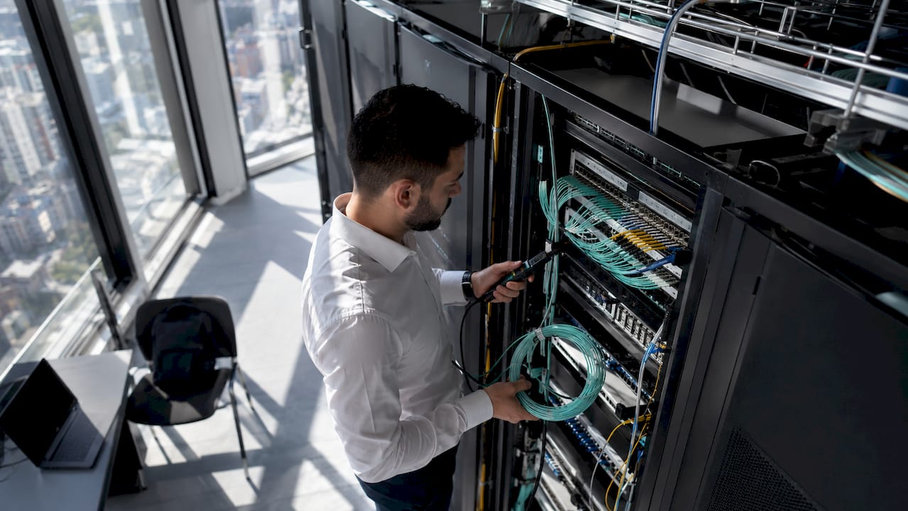
A fiber optic backbone is defined as the central, high-capacity cabling system that connects a building’s main distribution frame (MDF) to each intermediate distribution frame (IDF) across floors and zones. For modern commercial offices, fiber optic backbone office design is no longer optional. Industry standards TIA/EIA-568 and ISO/IEC 11801 both mandate fiber for vertical backbone runs exceeding 100 meters, and the benefits of fiber optics over copper at those distances are decisive: higher bandwidth, immunity to electromagnetic interference, and a lifespan that outlasts most office buildout cycles. Getting the design right from the start determines whether your network grows with the business or fights it.
What fiber optic cables and components are right for your office backbone?
Cable selection is the first technical decision in any office backbone project, and the wrong choice here creates problems that are expensive to fix later. TIA/EIA-568 standards recommend 6–24 core single-mode OS2 cable for vertical backbone runs, with at least 30% spare fibers built into every design. OS2 single-mode fiber handles long vertical runs without signal degradation, making it the right choice for multi-floor commercial buildings.
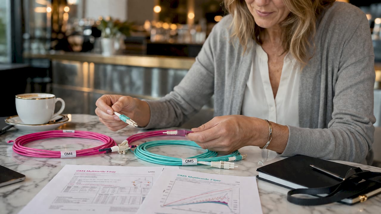
For horizontal distribution and high-speed applications within a floor, OM4 or OM5 multimode fiber is the standard. OM5 supports wavelength-division multiplexing, which means a single strand can carry multiple data channels simultaneously. That capability matters when you are planning for 40G or 100G network speeds.
High-density offices benefit most from MPO/MTP trunk cables. These pre-terminated assemblies carry 12 or 24 fibers in a single connector, which reduces installation time and patch panel complexity significantly. For termination at the rack, MPO cassette modules convert MPO trunks to individual LC/UPC ports, giving you clean, manageable connections at each IDF.
Enclosure selection affects long-term manageability. Modular enclosures like the VarioConnect 3HE support up to 288 fibers in 3U of rack space and accept both splice and MPO modules. That density reduces rack space usage by up to 50% compared to fixed-configuration enclosures. The tool-free module installation also speeds up staged migrations when you need to add capacity without taking the network offline.
Pro Tip: Always specify bend-insensitive fiber for any run that passes through tight conduit bends or dense cable trays. Standard fiber degrades measurably under micro-bending stress, and the performance loss is difficult to diagnose after installation.
| Component | Recommended specification |
|---|---|
| Vertical backbone fiber | OS2 single-mode, 6–24 cores, 30% spare capacity |
| Horizontal/high-speed runs | OM4 or OM5 multimode with MPO/MTP trunks |
| Rack enclosure | Modular 3U enclosure, up to 288 fibers |
| Connector standard | LC/UPC for endpoints, MPO for trunk aggregation |
| Spare conduit | Minimum one empty conduit per pathway for future pulls |
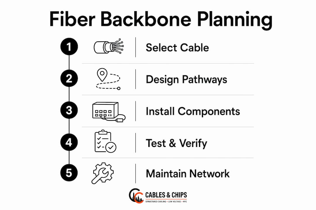
How to plan the physical infrastructure for fiber backbone deployment
Physical pathway design determines whether your fiber survives installation and performs reliably for years. TIA/EIA-568 sets clear limits: cable tray fill ratios must stay at or below 40%, conduit fill must not exceed 50%, and the minimum bend radius for any fiber run is 10 times the cable diameter, with a hard floor of 50mm. Exceeding these limits causes micro-bending loss that degrades signal quality permanently.
Vertical riser management requires consistent mechanical support. Fiber cables need support every 1.5–2 meters along vertical runs to prevent the cable’s own weight from creating strain. Without that support, the fiber core shifts inside the jacket over time, and signal loss increases gradually until the link fails a certification test.
Separation from copper cabling is non-negotiable. Copper carries electromagnetic interference that affects nearby electronics, and physical contact between fiber and copper bundles creates mechanical stress on the fiber jacket. The minimum separation is 300mm, enforced by dedicated dividers in shared trays. For network closet organization, this means planning separate tray sections or entirely separate pathways before any cable is pulled.
- Map all MDF and IDF locations on the building floor plan before ordering cable.
- Calculate tray and conduit fill at maximum planned capacity, not current load.
- Designate separate pathways or tray sections for fiber and copper with 300mm minimum clearance.
- Install vertical cable supports at 1.5-meter intervals in all riser sections.
- Pull at least one spare conduit alongside every active pathway for future expansion.
- Document all pathway routes, conduit IDs, and tray assignments before installation begins.
| Pathway parameter | Required specification |
|---|---|
| Cable tray fill ratio | 40% maximum |
| Conduit fill ratio | 50% maximum |
| Minimum bend radius | 10× cable diameter, floor of 50mm |
| Vertical support interval | Every 1.5–2 meters |
| Fiber-to-copper separation | 300mm minimum with dedicated dividers |
What are the best practices for fiber optic installation and termination?
Installation quality determines the long-term reliability of the entire backbone. A well-designed system fails if the cable is handled carelessly during the pull. Bend-insensitive fiber reduces the risk of signal degradation in tight spaces, but it does not eliminate the need for proper technique. Every pull must respect the cable’s minimum bend radius and maximum pulling tension, both of which are printed on the cable’s data sheet.
Follow these steps for a reliable fiber backbone installation:
- Pre-pull inspection: Verify all conduits and trays are clear, clean, and within fill limits before pulling any cable.
- Cable pulling: Use a pulling grip rated for the cable’s weight. Never exceed the manufacturer’s maximum pulling tension. Assign one person to feed and one to pull.
- Slack management: Leave a minimum of 1 meter of slack at each termination point. This allows for re-termination without pulling new cable.
- Termination: Use factory-polished LC/UPC connectors or MPO cassette modules for field terminations. Field-polished connectors introduce higher insertion loss and require more skill to execute correctly.
- Labeling: Label every fiber at both ends before testing. Use a consistent naming convention tied to your as-built documentation.
- Testing: Test every link with an optical loss test set (OLTS) and an optical time-domain reflectometer (OTDR). The OLTS confirms end-to-end loss meets TIA/EIA-568 limits. The OTDR locates any splice, bend, or connector anomaly along the run.
- Documentation: Record all test results, link IDs, and fiber assignments in a permanent as-built record.
Spare fiber capacity of at least 30% must be verified at this stage. Count active fibers, count total installed fibers, and confirm the reserve before signing off on the installation. Skipping this step is the single most common cause of emergency re-cabling projects two or three years after a buildout.
Pro Tip: When planning office connectivity, treat the OTDR trace as a permanent record, not just a pass/fail check. Store the trace file with your as-built documentation. If a link degrades later, the original trace gives you a baseline to compare against and cuts troubleshooting time significantly.
What mistakes should IT teams avoid in fiber backbone design?
The most expensive mistakes in office fiber backbone projects are not technical errors. They are planning failures that show up years after installation. Designing without spare capacity is the most common. A backbone installed at 100% utilization forces a full re-pull the moment the business adds a floor, a server, or a new application that demands dedicated fiber. The 30% reserve rule exists precisely to prevent that scenario.
Common pitfalls to avoid:
- Underestimating growth: Plan for the network the business will need in five years, not the one it has today. Office relocations and expansions often require new fiber paths that were never accounted for in the original design.
- Ignoring bend radius in conduit: Tight 90-degree conduit bends are the most frequent cause of micro-bending loss. Bend-insensitive fiber reduces this risk, but proper conduit sweeps eliminate it.
- Skipping modular enclosures: Fixed-configuration patch panels fill up fast in high-density offices. Modular enclosures let you add capacity without replacing the entire panel.
- Mixing fiber and copper in the same tray section: EMI from copper affects nearby electronics, and physical contact damages fiber jackets over time. Separate pathways are not optional.
- Poor documentation: An unlabeled fiber plant is a liability. Every move, add, or change takes longer, and every outage is harder to diagnose.
The backbone is not just cabling. It is the foundation every application, user, and device in the building depends on. A network built without proper planning for capacity, separation, and documentation will cost more to fix than it would have cost to build correctly the first time.
When planning an office relocation or new buildout, the office relocation planning process should include a fiber backbone assessment as a mandatory step, not an afterthought.
Key takeaways
A well-designed fiber optic backbone requires OS2 or OM4/OM5 cable, at least 30% spare fiber capacity, proper pathway separation, and full OLTS/OTDR testing to deliver reliable, future-ready office network infrastructure.
| Point | Details |
|---|---|
| Cable selection matters | Use OS2 single-mode for vertical runs and OM4/OM5 multimode for high-speed horizontal links. |
| Spare capacity is mandatory | Build in at least 30% spare fibers to avoid costly re-cabling as the network grows. |
| Physical pathway rules are strict | Keep tray fill at or below 40%, maintain 300mm fiber-to-copper separation, and support vertical runs every 1.5–2 meters. |
| Test every link completely | Use both OLTS and OTDR testing and store all results in permanent as-built documentation. |
| Modular enclosures save space | High-density modular enclosures reduce rack space usage by up to 50% and simplify future upgrades. |
What 40 years of fiber backbone work has taught me
Most fiber backbone failures I have seen were not caused by bad cable or faulty connectors. They were caused by decisions made in the first hour of a project, before a single cable was pulled. Someone chose to skip the spare conduit. Someone decided the tray fill limit was a suggestion. Someone assumed the business would not grow that fast.
The backbone is the one part of your network infrastructure that is genuinely difficult to fix after the fact. You can swap a switch. You can add an access point. You cannot easily re-pull a vertical riser through a finished building without significant disruption and cost. That reality changes how you should think about every design decision.
Viewing the backbone as long-term highway infrastructure rather than a short-term cabling project is the mindset shift that separates networks that age well from networks that become problems. I also recommend hybrid designs that combine structured backbone fiber with Power over Fiber for edge devices like Wi-Fi access points and remote monitoring equipment. That approach keeps the core backbone clean while extending fiber’s reach to every corner of the office.
Neat, documented cable management is not cosmetic. An orderly network closet is one where moves, adds, and changes happen in minutes instead of hours. It is also one where outages get resolved before they become incidents. If you want to understand what that looks like in practice, the structured cabling buildout process is worth reviewing before your next project starts.
— Ken
Fiber optic infrastructure support from Cables and Chips
Cables and Chips designs and installs fiber optic backbone systems for commercial offices throughout New York City. With more than 40 years of experience in low voltage and data network infrastructure, the team handles everything from pathway planning and cable pulling to termination, testing, and as-built documentation.
Every project starts with a site survey to assess existing pathways, IDF locations, and current network demands. From there, Cables and Chips specifies the right cable types, enclosures, and connector standards for the building. The result is a tested, labeled, and documented backbone that meets TIA/EIA-568 requirements and is built to grow with your business. Explore the full range of fiber optic components and review the structured cabling components guide to see what a complete backbone deployment involves. Contact Cables and Chips to schedule a site survey.
FAQ
What is a fiber optic backbone in an office network?
A fiber optic backbone is the high-capacity cabling system that connects the main distribution frame to each intermediate distribution frame across floors. TIA/EIA-568 mandates fiber for vertical runs exceeding 100 meters.
What fiber cable type is best for office backbone runs?
OS2 single-mode fiber is the standard for vertical backbone runs in multi-floor commercial buildings. OM4 or OM5 multimode fiber is recommended for high-speed horizontal links supporting 40G and 100G speeds.
How much spare fiber capacity should a backbone design include?
Industry best practice requires at least 30% spare fiber capacity in every backbone design. This reserve accommodates future growth and repairs without requiring a full cable re-pull.
How far apart should vertical fiber cable supports be placed?
Fiber cables in vertical risers require mechanical support every 1.5–2 meters. Without consistent support, the cable’s own weight creates strain that permanently degrades signal quality over time.
What is the minimum separation between fiber and copper cables?
Fiber and copper cables must be separated by at least 300mm, enforced by dedicated dividers in shared trays. This prevents electromagnetic interference from copper and protects fiber jackets from mechanical damage.