
Most commercial buildings in New York City have a cabling problem they don’t know about yet. The wiring installed during the last renovation is already undersized, unlabeled, or running too close to electrical conduit. When the next technology upgrade hits, or when a critical link goes down on a Monday morning, that hidden problem becomes a very visible and expensive one. Understanding how building cabling infrastructure works is not just a technical exercise. It is the difference between a network that supports your business for the next decade and one that forces a costly, disruptive overhaul in three years.
Table of Contents
- Understanding structured cabling and its components
- Key standards and technical requirements for commercial building cabling
- Planning and designing cabling infrastructure for scalability and future growth
- Best practices for installation and administration to ensure reliability
- Comparing cable types and their roles in commercial building networks
- Why many building cabling projects fail and how to avoid costly mistakes
- How Cables & Chips can support your NYC building cabling projects
- Frequently asked questions
Key Takeaways
| Point | Details |
|---|---|
| Structured cabling basics | Commercial building cabling follows a hierarchical star topology with six subsystems for scalability and organization. |
| Adhere to standards | TIA standards define cable types, distances, and labeling practices essential for reliable and future-proof networks. |
| Plan for growth | Proper pathway sizing and topology choices at design phase avoid costly retrofits and support emerging technologies. |
| Labeling reduces downtime | Accurate, unique labeling and digital infrastructure management drastically cut troubleshooting time. |
| Professional installation matters | Compliant installation practices ensure safety, performance, and long-term network reliability. |
Understanding structured cabling and its components
Structured cabling is a standardized system of cabling and hardware that provides a telecommunications infrastructure for a building. Unlike point-to-point wiring, where each device connects directly to another, structured cabling organizes every connection through a central, logical hierarchy. The result is a system that is easier to manage, easier to troubleshoot, and far easier to upgrade.
The industry standard governing this approach is TIA/EIA cabling standards, which define how commercial buildings should be wired for voice, data, video, and security systems. According to ANSI/TIA-568.1-D, structured cabling uses six subsystems arranged in a hierarchical star topology, meaning every connection traces back to a central distribution point rather than daisy-chaining from device to device. This matters because it means a problem in one work area never cascades into the backbone.
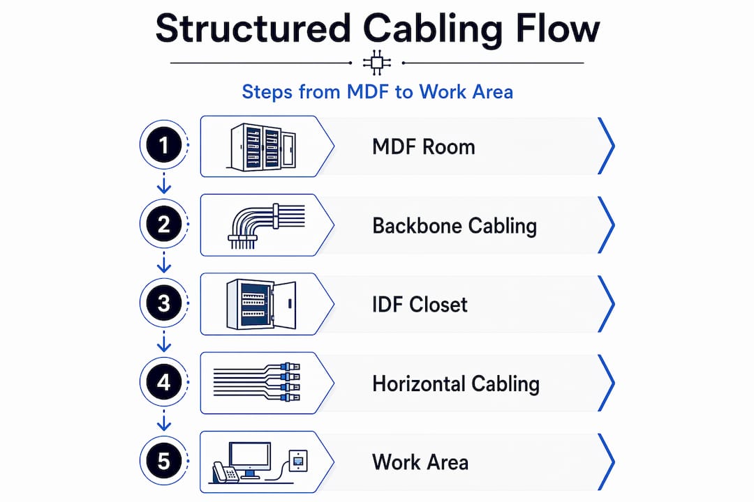
The six subsystems are:
- Entrance facilities: Where outside telecommunications lines enter the building and connect to the internal infrastructure.
- Equipment rooms: Centralized spaces housing major hardware like servers, main distribution frames (MDF), and core switching equipment.
- Backbone cabling: The high-capacity vertical runs connecting equipment rooms to telecommunications rooms on each floor, typically using fiber optic cable.
- Telecommunications rooms (IDF closets): Floor-level distribution points where backbone cabling terminates and horizontal cabling begins.
- Horizontal cabling: The runs from each IDF closet to individual work area outlets, almost always copper.
- Work areas: The endpoints where devices connect, including desks, conference rooms, and access control panels.
Structured CAT6 cabling is the most common horizontal medium in commercial office builds today, and for good reason. It supports the speeds and densities that modern offices actually need. But the cable itself is only one piece of a much larger system.
Key standards and technical requirements for commercial building cabling
Now that you understand the cabling components, let’s explore the standards and technical requirements ensuring your infrastructure meets performance and reliability expectations.
The two primary standards governing commercial cabling performance are ANSI/TIA-568.1-D for system architecture and TIA-568.3-D for optical fiber cabling. Together, they define what your infrastructure must deliver to be considered compliant and future-ready.
Here are the core technical requirements every IT director and building manager should know:
- Cat6A copper horizontal cabling must support 10 Gbps up to 100 meters channel length. That 100-meter limit is the total channel, not just the cable run. It includes patch cords at both ends, so your actual cable run must stay under 90 meters.
- Backbone cabling uses OM4+ multimode or OS2 singlemode fiber, with a minimum of two fibers per channel. OM4 supports 40 Gbps and 100 Gbps over medium distances. OS2 singlemode handles longer runs, up to several kilometers, making it the right choice for multi-building campuses or high-rise verticals.
- Testing and certification must be performed on every cable run before the system goes live. This means using a certified tester like a Fluke DSX to verify insertion loss, return loss, and near-end crosstalk on copper, and optical loss on fiber. Cable testing and certification is not optional. It is the only way to confirm your infrastructure actually performs to spec.
- Labeling and administration follow ANSI/TIA-606-D, which requires unique identifiers on both ends of every cable, every port, and every piece of hardware. Poor labeling causes 20 to 30% of downtime in commercial environments. Integrating your cable records with a DCIM (Data Center Infrastructure Management) platform cuts troubleshooting time from hours to minutes.
Pro Tip: When specifying Cat6A for a new build or renovation, always request augmented shielded twisted pair (S/FTP) rather than unshielded (U/UTP) in environments with high electrical interference, like mechanical floors or buildings with dense power distribution. The shielding cost is minimal compared to the performance gain.
Following network infrastructure best practices from the design phase forward is the single most effective way to avoid compliance failures and unexpected performance degradation.
Planning and designing cabling infrastructure for scalability and future growth
With technical standards clear, let’s focus on how to plan your cabling infrastructure to handle future demands and avoid expensive surprises.
The most expensive mistake in cabling infrastructure design is not choosing the wrong cable type. It is under-sizing the pathways that carry the cables. Conduit, cable trays, and raceways filled beyond 40% capacity at installation leave no room for future additions. According to BICSI guidelines 002-2024, pathways sized at 40 to 50% fill enable AI-era fiber densities like 864 fibers per rack, and retrofitting those pathways later costs 5 to 10 times more than getting it right at the start.
The topology decision is equally consequential. Hierarchical star topology ensures that changes in a work area, like moving a team or adding a conference room, do not affect the backbone infrastructure. This makes it the right choice for commercial buildings planning for 40 Gbps and beyond.
Here is how the major planning variables compare:
| Planning factor | Under-designed approach | Standards-compliant approach |
|---|---|---|
| Pathway fill ratio | 70-80% at installation | 40-50% at installation |
| Topology | Point-to-point or flat | Hierarchical star |
| Fiber count per run | Minimum for current need | 2x to 4x current need |
| Retrofit cost risk | High (5-10x original cost) | Low |
| Future technology support | Limited | 40 Gbps+ ready |
Two additional planning considerations that often get overlooked:
- AI and high-density computing are driving fiber counts in commercial buildings to levels that were unthinkable five years ago. If your building houses any technology-intensive tenants, plan for 864-fiber trunk cables in backbone pathways, not 12 or 24.
- Fiber installation and pathway sizing decisions made during a renovation are nearly impossible to reverse without significant disruption. Treat pathway capacity as a long-term asset, not a short-term line item.
Pro Tip: During any tenant improvement or base building renovation, request that the general contractor install empty conduit sleeves between every IDF closet and the MDF, even if you are not running fiber today. The cost is negligible at rough-in. The cost to core-drill and sleeve after the fact is not.
Good network closet organization starts at the design phase. A well-planned IDF layout with proper rack spacing, airflow, and cable management makes every future upgrade faster and cleaner.

Best practices for installation and administration to ensure reliability
Understanding planning is vital, but execution quality determines real-world reliability, so let’s cover installation and administration best practices next.
In New York City, cabling installations in commercial buildings must comply with both NYC building codes and fire codes, including requirements for plenum-rated cable in air-handling spaces and proper firestopping around any penetrations. NYC building and fire codes are not suggestions. Violations create liability and can force expensive remediation during future inspections or tenant fit-outs.
Key installation best practices include:
- Use dedicated cable trays and conduit runs for data cabling, separate from electrical runs.
- Maintain a minimum 12-inch separation between data cables and 120V power lines, and at least 24 inches from high-voltage or fluorescent lighting circuits.
- Never exceed the minimum bend radius for the cable type. For Cat6A, that is typically four times the cable diameter.
- Use proper cable management in every IDF and MDF: horizontal managers, vertical managers, and velcro ties (never zip ties on active cable bundles).
- Terminate all copper to patch panels, not directly to switch ports. Patch panels protect your switch ports and make moves, adds, and changes fast.
For documentation and labeling, follow this sequence on every project:
- Assign a unique cable ID to every run before installation begins.
- Label both ends of every cable with that ID before pulling.
- Record the route, origin, and destination in your cable management system.
- Test every run with a certified tester and attach the test results to the cable record.
- Photograph the completed IDF and MDF installations and store them with the project documentation.
Labeling both ends and documenting cable routes is the difference between a 10-minute fix and a 4-hour outage when something goes wrong at 2 a.m.
Pro Tip: Require your cabling contractor to deliver a complete as-built package at project closeout. This should include test reports for every run, labeled photos of each closet, and a spreadsheet or DCIM export of all cable IDs and routes. If they can’t provide this, find a contractor who can.
Structured cabling installation done to this standard is what separates a network that works reliably for 15 years from one that causes problems in 18 months.
Comparing cable types and their roles in commercial building networks
After grasping installation logistics, it’s crucial to understand the cable types that form the backbone of commercial building networks.
Choosing the wrong cable for a given application is a common and costly error. Here is a clear breakdown of the types of building cabling used in commercial environments today.
| Cable type | Max speed | Max distance | Best use case | Relative cost |
|---|---|---|---|---|
| Cat6 | 1 Gbps | 100 m | Low-density horizontal runs | Low |
| Cat6A | 10 Gbps | 100 m | Standard horizontal cabling | Moderate |
| OM3 multimode fiber | 40 Gbps | 100 m | Short backbone runs | Moderate |
| OM4 multimode fiber | 100 Gbps | 150 m | Mid-range backbone runs | Moderate-high |
| OS2 singlemode fiber | 100 Gbps+ | 10 km+ | Long backbone, campus, riser | Higher |
Key points to guide your selection:
- Cat6 vs. Cat6A: Cat6 is adequate for 1 Gbps workstations but cannot reliably support 10 Gbps at full channel length. For any new commercial installation, Cat6A up to 100 meters is the minimum standard. The cost difference per port is small. The performance difference is significant.
- OM3 vs. OM4: OM3 is acceptable for short backbone runs under 100 meters. OM4 is the better investment for any run where you anticipate 40 Gbps or 100 Gbps in the next five years.
- OS2 singlemode: This is the right choice for any backbone run exceeding 300 meters, any inter-building connection, or any environment where maximum future bandwidth is a priority. OS2 has essentially no distance limitation for commercial building purposes.
Bulk cable options and fiber optic cabling selections should always be made in the context of your full infrastructure plan, not in isolation. A cable that is cheap to buy but wrong for the application will cost far more to replace.
Why many building cabling projects fail and how to avoid costly mistakes
Here is an uncomfortable truth we have seen play out in commercial buildings across New York City over more than 40 years in this business: most cabling failures are not technical failures. They are planning failures. The cable itself rarely causes the problem. The decisions made before a single cable was pulled are almost always the root cause.
The three most common and expensive mistakes are under-sized pathways, ignored labeling standards, and no plan for future technology. Each one seems like a reasonable shortcut at the time. Each one becomes a serious liability within a few years.
Under-sized pathways are the most financially damaging. Retrofitting cable pathways costs 5 to 10 times more than designing them correctly at the outset. In a Manhattan high-rise, that difference can mean the gap between a $50,000 upgrade and a $400,000 renovation that requires tenant relocation and structural work. The fill ratio decision at design time is one of the highest-leverage choices a building manager or IT director makes.
Ignored labeling standards create a different kind of damage. Poor labeling causes 20 to 30% of downtime in commercial environments. That downtime has a direct dollar cost in lost productivity, and an indirect cost in the trust of every tenant or department that depends on the network. Integrating cable records with a DCIM platform is not a luxury for enterprise data centers. It is a practical necessity for any building with more than two IDF closets.
The third failure, ignoring future technology demands, is the one that surprises people most. AI workloads, dense wireless access point deployments, and building automation systems are all driving fiber counts and bandwidth requirements that would have seemed extreme five years ago. The importance of network infrastructure planning cannot be overstated. A building wired for today’s minimum requirement is already behind.
Our advice: follow TIA, BICSI, and ANSI standards from day one. Oversize your pathways. Label everything. Document everything. And engage a contractor who will hand you a complete as-built package at closeout, not just a bill.
How Cables & Chips can support your NYC building cabling projects
Armed with knowledge and industry perspective, partnering with experienced local professionals is your next best step to ensure successful cabling infrastructure deployment in NYC commercial buildings.
At Cables & Chips, we have been designing and installing structured cabling infrastructure in New York City commercial buildings for more than 40 years. We work directly with building managers, IT directors, and enterprise tenants to deliver structured Cat6 cabling installation that meets ANSI/TIA standards, passes certification testing, and is fully documented at closeout. Our fiber installation services cover everything from OM4 backbone runs to OS2 inter-floor risers, sized for the demands of today and the demands of the next decade. We also provide network closet organization services to bring existing infrastructure up to a standard that actually supports your operations. Schedule a site survey with our team before your next renovation or tenant improvement project. Getting us involved early is the most cost-effective decision you can make.
Frequently asked questions
What is structured cabling and why is it important in commercial buildings?
Structured cabling is a standardized, organized approach to network wiring that connects voice, data, video, and security systems in a single, manageable infrastructure, reducing downtime and supporting future technology growth without full rewiring.
What are the maximum recommended cable lengths for Cat6A and fiber optic horizontal cabling?
Cat6A horizontal cabling supports 100 meters as the maximum channel length; backbone fiber distances extend much further, with OM4 multimode reaching several hundred meters and OS2 singlemode supporting runs of 10 kilometers or more.
How does proper labeling impact network downtime?
Poor labeling causes 20 to 30% of downtime in commercial networks, and combining unique cable IDs with a DCIM platform can reduce troubleshooting time from hours to minutes.
Why is it important to plan cable pathways with future growth in mind?
Pathway sizing at 40 to 50% fill at installation supports the high fiber densities required by emerging technologies like AI infrastructure, while retrofitting those pathways after the fact costs 5 to 10 times more than doing it right the first time.
Recommended
- About Cables & Chips NYC | Low Voltage Contractor – Cables & Chips | Low Voltage Contractor NYC
- Structured CAT6 Cabling Installation NYC | CAT6 & CAT6a – Cables & Chips | Low Voltage Contractor NYC
- Why Network Infrastructure Matters | Low Voltage Contractor NYC – Cables & Chips | Low Voltage Contractor NYC
- Structured Cabling NYC | Low Voltage Contractor | Cables & Chips – Cables & Chips | Low Voltage Contractor NYC