
WiFi Access Point Placement Best Practices for IT Teams
WiFi access point placement best practices are defined as the set of mounting, spacing, and channel planning decisions that maximize signal coverage while minimizing co-channel interference across a commercial environment. The industry term for this discipline is wireless network design, and it applies equally to a 2,000-square-foot office and a multi-floor enterprise facility. Getting it right requires more than picking a spot on the ceiling. It demands predictive modeling tools like NetSpot, deliberate 15–20% coverage overlap between adjacent access points, and channel assignments that follow the 1, 6, 11 rule on 2.4 GHz. When these elements align, the result is a network that performs reliably under real load.
1. How mounting height and location affect wifi signal strength
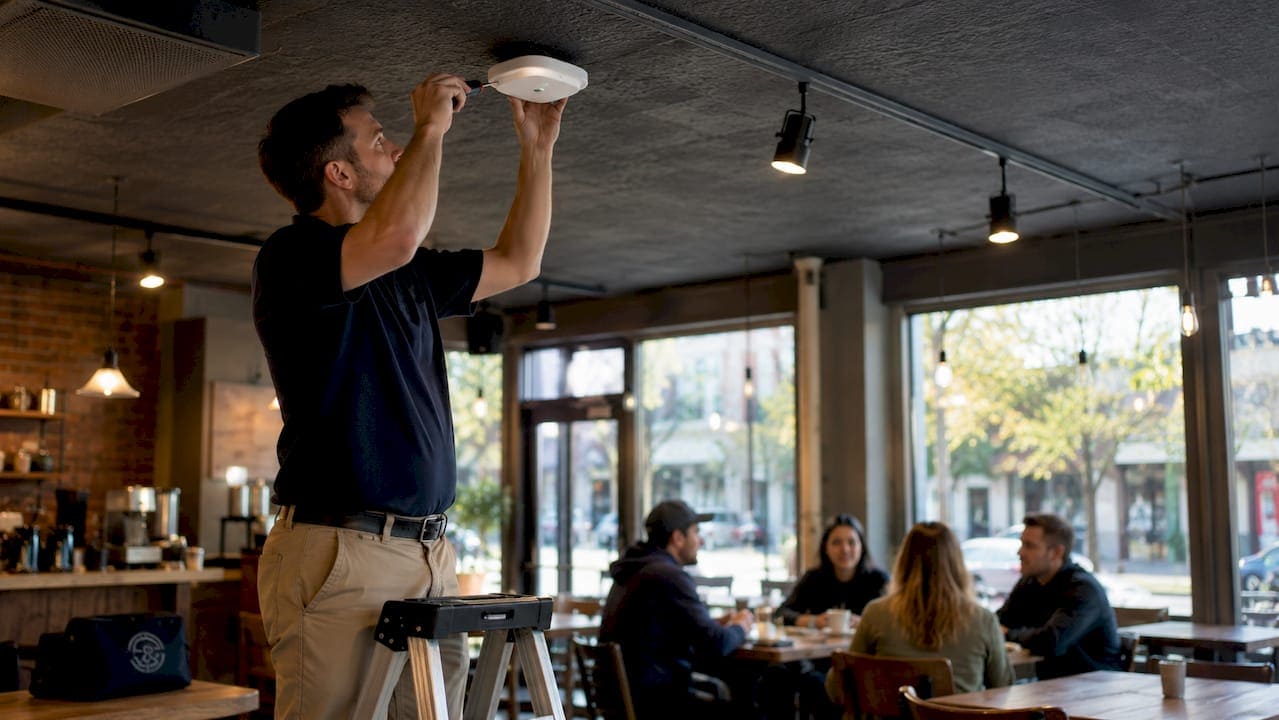
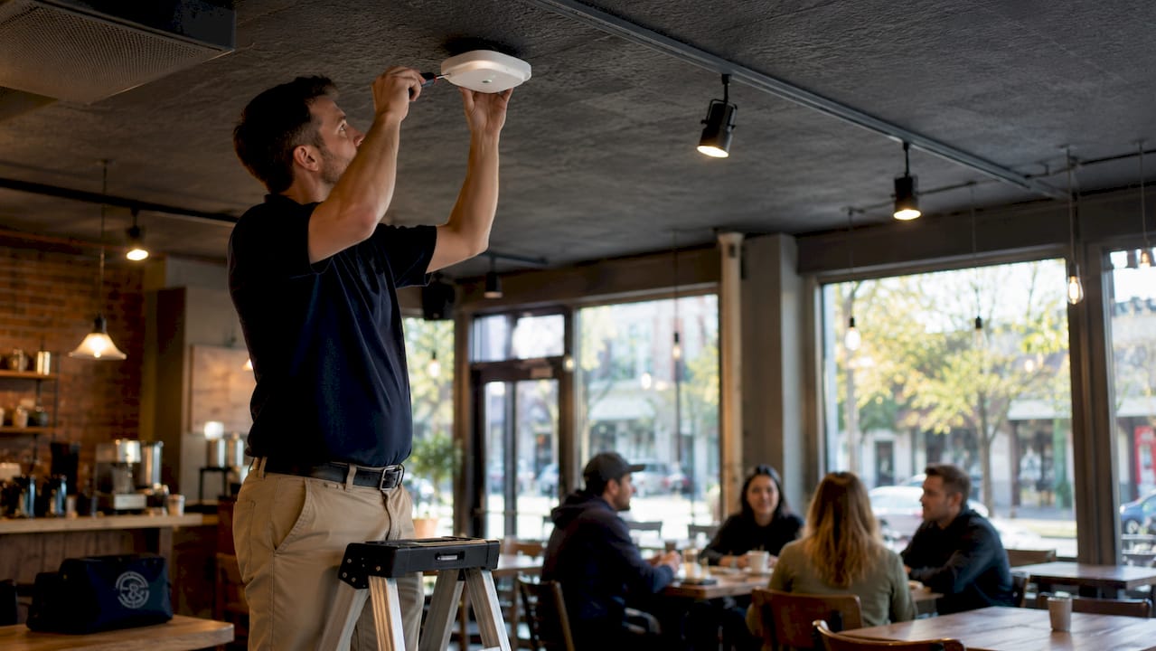
Mounting height is the single most controllable variable in access point deployment. The optimal range is 8–15 feet, which balances broad coverage with reduced interference from furniture, equipment, and human bodies. Ceiling mounting is the preferred method for open floor plans because the AP radiates signal downward and outward with minimal obstruction.
Wall mounting works in corridors and hotel rooms where ceiling access is limited. When you mount an AP on a wall, the LED indicators face downward to match the internal antenna radiation pattern. Reversing that orientation misaligns the RF propagation and reduces effective coverage.

Avoid placing APs inside closets, above soffits, or behind metal shelving. Obstructed APs fail regardless of configuration because the signal cannot pass through the obstruction cleanly. Think of it the way you think about a light bulb: a bulb inside a cabinet does not light the room.
Pro Tip: Treat every AP like a light source. If a wall, cabinet, or mechanical unit would block a lamp, it will block your signal too. Clear sightlines to the coverage zone are non-negotiable.
2. Spacing strategy and coverage overlap for seamless roaming
Spacing access points correctly is as important as placing them in the right location. Professional wifi designs maintain 15–20% overlap between adjacent AP coverage areas to support smooth client handoffs during roaming. That overlap gives a client device enough signal from the next AP to transition before losing the current one.
The minimum recommended spacing in commercial environments is 20 feet between APs. Closer spacing without a matching reduction in transmit power creates excessive overlap. Excessive overlap causes two specific problems:
- Roaming confusion. Client devices receive strong signals from multiple APs simultaneously and struggle to decide which one to associate with.
- Sticky clients. Devices hold onto a distant AP even when a closer one is available, degrading throughput for the entire cell.
Coverage-oriented designs prioritize signal reach. Capacity-oriented designs prioritize the number of devices per AP. In high-density environments like conference centers or trading floors, capacity-oriented design wins. That means more APs at lower transmit power, creating smaller, focused radio cells that serve more devices without overlapping destructively.
3. Using predictive modeling and site surveys to prevent dead zones
Predictive modeling is the process of simulating signal propagation through a building’s actual materials before a single AP is installed. Tools like NetSpot validate placement plans by accounting for wall and floor attenuation, giving IT teams a tested design rather than a guess.
Material attenuation is a physics problem, not a configuration problem. Drywall causes 3–5 dB signal loss. Concrete causes significantly higher attenuation. Inputting accurate material types into your modeling software changes the output dramatically. A plan designed for drywall will fail in a concrete-and-steel building.
Site surveys add a second layer of validation. They reveal active interference sources, areas of high device density, and physical obstructions that floor plans do not show. Multi-story buildings require vertical staggering of APs to reduce intra-floor interference from APs on adjacent floors.
- Map every wall material type before modeling
- Input accurate attenuation values for concrete, glass, and drywall
- Identify interference sources such as microwaves, Bluetooth devices, and neighboring networks
- Verify that the target signal strength at the edge of each coverage zone reaches at least -67 dBm
- Stagger AP positions vertically in multi-story deployments
Pro Tip: Run a post-installation validation survey using the same tool you used for predictive modeling. Comparing predicted vs. actual coverage identifies gaps before users report them.
4. Mounting options and orientation: ceiling vs. wall vs. in-ceiling
The mounting method determines how cleanly the AP’s antenna pattern reaches its intended coverage zone. Each option has a specific use case.
| Mount Type | Best Use Case | Key Consideration |
|---|---|---|
| Ceiling mount | Open floor plans, warehouses | Provides even downward coverage; easiest to maintain |
| Wall mount | Corridors, hotel rooms | LED must face down; antenna alignment is critical |
| In-ceiling mount (e.g., Paramount) | Finished ceilings, concealed installs | Preserves antenna pattern; avoids ceiling void signal loss |
In-ceiling mounts like Paramount preserve the intended antenna radiation pattern. Placing an AP blindly inside a ceiling void can reduce signal strength by 3–5 dB and makes future maintenance significantly harder. An in-ceiling enclosure solves both problems by holding the AP flush with the ceiling tile while keeping the antenna oriented correctly.
Document every mounting position at installation. Record the AP model, mount type, ceiling height, and cable run length. That documentation cuts troubleshooting time in half when a device needs replacement or reconfiguration.
Pro Tip: Label each AP with a physical asset tag that matches your network management system. When a device goes offline at 2 a.m., your team should be able to find it in under two minutes.
5. Channel planning and transmit power for high-density environments
Channel planning is where most enterprise wifi deployments either succeed or fail at scale. 20 MHz channel widths in high-density deployments maximize the number of non-overlapping channels available, which directly reduces co-channel interference. Wider channels mean fewer options and larger interference zones.
- Use 20 MHz channels in dense deployments on both 2.4 GHz and 5 GHz
- Assign 2.4 GHz APs to channels 1, 6, or 11 only. These are the only three non-overlapping channels on that band.
- Use band steering to push capable clients to 5 GHz, which offers more non-overlapping channels and less congestion
- Reduce transmit power on individual APs to shrink cell size and enable more frequent channel reuse across the floor
- 40 MHz and 80 MHz channel widths increase the required AP spacing because their interference radius is proportionally larger
Cisco Meraki’s radio management features can automate channel and power adjustments based on real-time neighbor AP data. Automation helps, but it does not replace a well-designed initial channel plan. Automated systems correct drift; they do not fix a fundamentally flawed layout.
Pro Tip: Review your channel utilization reports quarterly. Client density changes as teams grow or reconfigure spaces, and your channel plan should change with it.
6. The most common mistake: more APs does not mean better wifi
Over-densifying APs without rigorous channel planning is the most common mistake in enterprise wifi deployments. Adding more hardware without adjusting transmit power and channel assignments creates co-channel interference that degrades performance across the entire network. Fewer, correctly placed APs consistently outperform excessive unsystematic deployment.
The fix is not always adding hardware. Reconfiguring transmit power, reassigning channels, and adjusting AP positions often resolves performance complaints without a single new device. Before you order more APs, run a site survey and review your channel utilization data. The problem is usually in the plan, not the hardware count.
You can use a PoE power budget calculator to verify that your switch infrastructure can support the AP density your design calls for. Underpowered PoE switches are a silent cause of intermittent AP failures that look like placement problems.
Key Takeaways
Effective wifi access point placement requires deliberate overlap, accurate material modeling, correct mounting orientation, and disciplined channel planning. More hardware without a sound design plan produces worse results, not better ones.
| Point | Details |
|---|---|
| Mount at 8–15 feet | Ceiling height in this range balances coverage area with interference reduction. |
| Maintain 15–20% overlap | Deliberate overlap supports smooth client roaming without causing sticky client issues. |
| Model materials before installing | Drywall and concrete attenuate signal differently; predictive tools prevent costly post-install fixes. |
| Use 20 MHz channels in dense spaces | Narrower channels maximize non-overlapping options and reduce co-channel interference. |
| Document every mount position | Clear records cut troubleshooting time and support faster hardware replacement. |
What 40 years of installs taught me about AP placement
The most expensive wifi problems I have seen were not caused by bad hardware. They were caused by good hardware placed without a plan. A client in a Manhattan high-rise once had 40 access points deployed across three floors and still had dead zones in every conference room. The issue was not coverage. It was co-channel interference from APs placed too close together with no channel separation. We removed eight APs, adjusted transmit power on the remaining ones, and the network performed better than it ever had.
The physics of signal propagation do not negotiate. Concrete walls, elevator shafts, and mechanical rooms will kill your signal regardless of what the AP’s spec sheet says. The teams that get this right treat wifi design in NYC as a site-specific engineering problem, not a product selection problem. They survey first, model second, and install third.
My other consistent observation: clean, accessible installs save money over time. An AP mounted with a Paramount in-ceiling enclosure, labeled, and documented takes 10 minutes to replace. An AP zip-tied to a conduit inside a ceiling void takes an hour to find and another hour to swap. That difference compounds across every service call for the life of the network.
The right question is not “how many APs do I need?” The right question is “where exactly should each AP go, at what power level, and on which channel?” Answer that question with a predictive model and a validated site survey, and the hardware count takes care of itself.
— Ken
Structured cabling is the foundation your APs depend on
Every access point in your network runs on two things: data and power. Both travel through your cabling infrastructure. A well-designed AP layout fails if the cabling behind it cannot deliver consistent PoE power and low-latency data throughput to each device.
Cables designs and installs the structured cabling infrastructure that supports commercial WiFi deployments across New York City. From CAT6A runs to PoE-capable patch panels, every component is tested, labeled, and documented to support your wireless network design. The structured cabling system components guide covers the full infrastructure stack that IT managers need to plan a reliable AP deployment. If your current cabling cannot support your AP density or power requirements, Cables can assess and upgrade it. Contact the team at 20 Vesey Street in Lower Manhattan or visit cables.nyc to schedule a site assessment.
FAQ
What is the optimal mounting height for a wifi access point?
The optimal mounting height for a commercial access point is 8–15 feet. This range provides broad coverage while reducing interference from furniture and equipment at floor level.
How much overlap should adjacent access points have?
Professional wifi designs target 15–20% overlap between adjacent AP coverage areas. This supports smooth client roaming without creating the co-channel interference that comes from excessive overlap.
Does adding more access points always improve coverage?
No. Adding APs without adjusting channel assignments and transmit power creates co-channel interference that degrades performance. Fewer correctly placed APs consistently outperform a dense, unplanned deployment.
What signal strength should I target at the edge of a coverage zone?
Target at least -67 dBm at the edge of each AP’s coverage zone. Signal weaker than this threshold causes connection drops and poor throughput for clients at the cell boundary.
Why does mounting orientation matter for wall-mounted APs?
Many AP models have internal antenna arrays designed for downward radiation. Mounting a wall AP with the LED facing upward misaligns the antenna pattern and reduces effective coverage across the intended area.