
Horizontal Cabling Explained for IT Managers and Facilities Teams
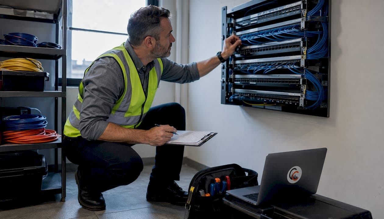
Horizontal cabling is the segment of a structured cabling system that runs from a telecommunications room (TR) to each work-area outlet (WAO), delivering data, voice, PoE, and multimedia services to end devices. Three facts define it from the start:
- Standard: ANSI/TIA-568 governs design, media selection, and testing requirements for horizontal cabling in commercial buildings.
- Topology: Every WAO must connect back to the horizontal cross-connect (HC) in a star topology — no daisy-chaining, no splices.
- Length limit: The permanent link (TR to WAO) may not exceed 90 meters; the full channel, including patch cords, tops out at 100 meters.
Cables and Chips has designed and installed horizontal cabling systems across commercial offices and secure facilities in New York City for more than 40 years, working directly from ANSI/TIA standards on every project.
How horizontal cabling fits inside a structured cabling system
Horizontal cabling is the final delivery layer. Above it sits backbone cabling, which connects the main distribution frame (MDF) to intermediate distribution frames (IDFs) and telecommunications rooms across floors or buildings. Horizontal cabling picks up where backbone leaves off: it runs from the HC inside the TR, through ceiling plenums, raised floors, or cable trays, and terminates at the WAO on the work floor.
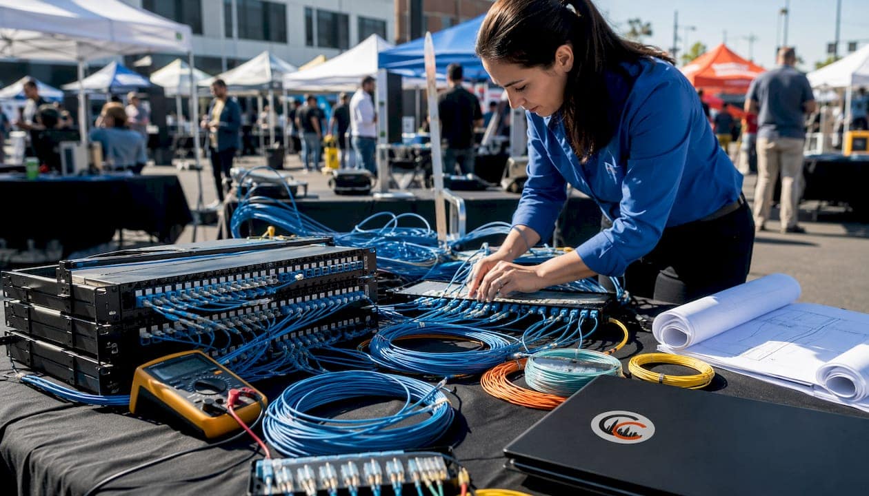
The permanent link is the fixed portion of this run, from the patch panel in the TR to the outlet jack at the workstation. Add equipment cords and patch cords at both ends and you have the full channel. Services delivered over this infrastructure include data (LAN), voice (VoIP), Power over Ethernet for Wi-Fi access points and IP cameras, video, and building automation signals.
Physically, horizontal cabling travels one of three common pathways: plenum-rated ceiling space (the most common in commercial offices), raised access floors, or open cable trays. The TR should sit on the same floor as the work areas it serves — a requirement, not a suggestion, under TIA/EIA-568.
What makes up a horizontal cabling link
Per ANSI/TIA-568, a horizontal cabling link consists of these components:
- Horizontal cable: The 4-pair twisted-pair copper or fiber run from the TR to the WAO. This is the permanent link.
- Telecommunications outlet/connector (WAO): The faceplate and jack at the workstation where devices plug in.
- Patch panel: Mounted in the TR; terminates the horizontal cable on the room side and connects to active equipment via patch cords.
- Patch cords and jumpers: Short, flexible cables at both the TR and WAO ends. Jumpers at the HC should not exceed 5 meters; total patch cord length across the channel should stay within roughly 10 meters.
- Consolidation point (CP): An optional mid-run transition point, typically in a ceiling or floor, that allows reconfiguration without pulling new cable to the TR. Using a CP alters the maximum permitted cable lengths and must be called out in the design spec.
- Multi-user telecommunications outlet assembly (MUTOA): A shared outlet cluster serving an open-plan area. Like a CP, it changes channel length calculations and must be documented.
Pro Tip: When specifying a CP or MUTOA, require the contractor to document the exact location and cable lengths on both sides. A CP that is not on the as-built drawing becomes an invisible failure point during future certification.
Choosing the right cable type for horizontal runs
ANSI/TIA-568 recognizes 4-pair twisted-pair copper (Cat5e, Cat6, Cat6A), multimode fiber, and single-mode fiber as valid horizontal media. Here is how to choose:
| Cable Type | Supported Bandwidth | Best Use Case | Notes |
|---|---|---|---|
| Cat5e | Up to 1 Gbps | Light-duty office, legacy refresh | Minimum acceptable for new installs |
| Cat6 | Up to 10 Gbps (short runs) | Standard commercial office | 10G reliable at shorter distances; cost-effective |
| Cat6A | Up to 10 Gbps (full 100 m) | PoE++, Wi-Fi 6/6E APs, high-density | Larger diameter; requires more pathway space |
| Multimode Fiber | Up to 100 Gbps (OM4/OM5) | High-speed server drops, long horizontal runs | Immune to EMI; no PoE capability |
| Single-mode Fiber | Up to 100 Gbps+ | Campus or inter-building horizontal | Lowest loss; highest future capacity |
Shielding options matter when EMI is a concern. Unshielded twisted pair (UTP) works in most commercial office environments. Foil-shielded (F/UTP or FTP) adds a foil layer around all four pairs, protecting against moderate EMI from HVAC equipment or fluorescent lighting. Fully shielded (S/FTP) wraps each pair individually and adds an outer braid, appropriate for industrial environments or data centers with dense power cabling nearby. Shielded cable requires grounded terminations throughout — a partial shield is worse than no shield.
- Cat5e is the floor for new installations, not the target.
- Cat6 covers most standard office deployments at a lower installed cost than Cat6A.
- Cat6A is the right call for any run serving a Wi-Fi 6/6E access point, a PoE++ device, or a 10G workstation at full channel length.
- Fiber eliminates EMI concerns entirely and carries no distance penalty within a floor, but it cannot deliver PoE.
Pro Tip: Bundling high-power PoE circuits without accounting for heat buildup can degrade performance. Cat6A’s larger conductor handles heat better than Cat6 in dense PoE bundles — specify it wherever you are running more than 12 PoE cables in the same pathway.
How horizontal cabling differs from backbone (vertical) cabling
Backbone cabling connects equipment rooms, TRs, and entrance facilities — it is the site distribution layer. Horizontal cabling is the access layer. The distinction matters when you are specifying, troubleshooting, or planning upgrades.
Both subsystems are complementary: backbone provides high-capacity inter-floor or inter-building distribution; horizontal delivers localized connectivity to individual workstations. A fiber backbone, for example, enables you to deploy higher-performance horizontal media on each floor without worrying about aggregated distance penalties.
Key operational differences:
- Run direction: Backbone runs vertically between floors or buildings; horizontal runs laterally across a single floor.
- Typical media: Backbone favors fiber for capacity and distance; horizontal uses copper for most workstations and fiber for specialized drops.
- Upgrade frequency: Horizontal cabling changes more often because it follows people and furniture. Backbone changes are rarer but more disruptive.
- Failure risk: Horizontal runs are more exposed to physical damage, accidental disconnection, and undocumented moves. Backbone failures affect entire floors or buildings.
How horizontal cabling should be installed
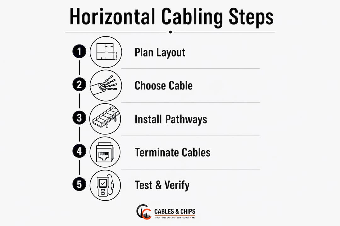
A properly installed horizontal system follows this sequence:
- Confirm TR location. The TR must be on the same floor as the work areas it serves. Verify this before any cable is pulled.
- Select pathways. Choose plenum ceiling, raised floor, or cable tray based on building construction and fire-rating requirements. Size pathways for future growth — at least 40% fill capacity remaining after initial install.
- Pull cable. Run each cable continuously from the patch panel to the WAO with no splices and no sharp bends. Maintain minimum bend radius throughout.
- Terminate. Punch down at the patch panel and terminate at the outlet jack. Keep untwisted pair length at terminations to 13 mm (0.5 in.) or less per TIA-568.
- Label. Every cable, patch panel port, and outlet jack gets a unique, permanent identifier at both ends. Use a consistent labeling scheme documented in the as-built drawings.
- Test and certify. Run a Tier 2 field test on every permanent link before sign-off (see the testing section below).
- Document. Deliver as-built drawings, test reports, and a cable-ID map to the owner. As-built documentation is not optional — it is the primary defense against costly future troubleshooting.
The 90-meter permanent link limit is the most commonly violated standard in horizontal installations. Exceeding it is a direct cause of certification failure and is not correctable without re-pulling cable.
Pro Tip: Specify two permanent links per work area in every RFP. Two drops per WAO support redundancy and multi-device workstations (a computer and a VoIP phone on separate runs). Omitting the second drop is one of the most expensive oversights to fix after construction.
Star topology, lifecycle risk, and what to require from contractors
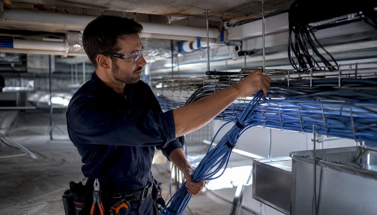
The star topology requirement means every WAO connects directly to the HC in the TR. No bridging between outlets, no daisy-chaining, and no splicing anywhere in the horizontal run. Splices degrade signal performance and make certification impossible to pass cleanly.
Horizontal cabling is the subsystem most exposed to physical movement and degradation over a building’s lifecycle. Furniture moves, tenant changes, and undocumented adds are the primary causes of degraded or failed links. Good pathways, consistent labeling, and complete documentation are the primary defenses.
What to require from any contractor before signing off:
- As-built drawings showing every cable route, TR location, and WAO position
- A unique cable ID on every run, matching the test report and the patch panel label
- Tier 2 field test reports for every permanent link, with pass/fail results and tester model recorded
- Written confirmation of the 90 m permanent link limit on all runs
- Two permanent links per work area, or documented justification for any single-drop location
- CP and MUTOA locations called out explicitly if used, with adjusted length calculations
How horizontal cabling is tested and what the results mean
Certification testing verifies that every permanent link meets the performance requirements of its rated category. A Tier 2 field tester (such as a Fluke Networks DSX CableAnalyzer or equivalent) performs the following tests on each link:
- Wiremap: Confirms correct pin-to-pin continuity and catches miswires, opens, and shorts.
- Length: Measures the electrical length of each pair. Flags runs exceeding 90 m.
- Insertion loss (attenuation): Measures signal loss across the link. Higher loss at longer runs or with lower-grade cable.
- NEXT (Near-End Crosstalk): Measures interference between adjacent pairs at the near end.
- ACR-F (Attenuation-to-Crosstalk Ratio, Far End): Measures signal-to-noise ratio at the far end of the link.
- Return loss: Measures signal reflected back toward the source from impedance mismatches.
Permanent link testing excludes patch cords; channel testing includes them. Most contractors certify the permanent link, which is the more conservative and reproducible standard. A link that passes permanent link testing will pass channel testing as long as compliant patch cords are used.
Deliverables to require after testing:
- Printed or PDF test reports for every link, labeled with the cable ID
- A cable-ID map correlating patch panel port, cable ID, and WAO location
- Tester model, firmware version, and calibration date on every report
- Warranty documentation from the installer tied to the test results
Pro Tip: Store test reports with the facility’s permanent records, not just in a contractor’s email thread. Cable testing records become critical evidence when a warranty claim or a performance dispute arises years later.
Common mistakes, maintenance tips, and when to call a professional
Red flags in an existing horizontal installation:
- Spliced cable runs anywhere between the TR and the WAO
- Missing or mismatched test documentation
- Single drop per workstation with no room to add a second
- Excessive cable bundles without derating consideration for PoE heat
- Unlabeled or inconsistently labeled patch panels and outlets
- Cables routed near high-voltage conduit or fluorescent ballasts without shielding
Maintenance practices that protect the investment:
- Periodic visual inspections of the TR and WAO terminations, especially after any furniture move
- Re-certification of affected links after any moves, adds, or changes (MAC work)
- Archiving test reports and as-built drawings in a facility management system, not just on a local laptop
- Checking network infrastructure for abandoned cable accumulation, which degrades airflow and complicates future work
Call a professional when:
- Any link fails certification and the cause is not immediately obvious
- A major reconfiguration affects more than a handful of drops
- Fiber termination or splicing is required
- Warranty or contract disputes require independent test verification
- The TR is disorganized to the point where tracing a cable requires guesswork
Key Takeaways
Horizontal cabling is the most frequently touched subsystem in any building, and the decisions made at installation time determine how much it costs to maintain, reconfigure, and certify for the life of the facility.
| Point | Details |
|---|---|
| Definition and standard | Horizontal cabling runs from the TR to the WAO; ANSI/TIA-568 governs all design and testing requirements. |
| Length limits | The permanent link must not exceed 90 m; the full channel including patch cords tops out at 100 m. |
| Star topology, no splices | Every WAO connects directly to the HC; splicing is prohibited and causes certification failure. |
| Two drops per work area | Specify two permanent links per WAO for redundancy and multi-device support — omitting the second is costly to fix later. |
| Cables and Chips | Cables and Chips designs, installs, tests, and documents horizontal cabling systems for commercial clients across New York City. |
A field perspective on what the standards don’t tell you
Most articles on horizontal cabling stop at the standard. The standard is necessary, but it does not tell you what actually goes wrong on real projects, and that gap is where installations get expensive.
The 90-meter limit is the clearest example. It looks generous on paper. In practice, a TR placed at one end of a long floor, combined with a furniture layout that routes cable around core walls, can push runs past 90 meters before anyone notices. By the time certification fails, the cable is in the ceiling and the contractor is pointing fingers. The fix is always the same: re-pull. The prevention is simple: measure the floor plan before pulling a single foot of cable, not after.
The two-drop rule is the other one that gets ignored. A single drop per workstation feels like a cost saving at bid time. Three years later, when every desk has a VoIP phone and a laptop dock, the facilities team is running extension cords and complaining about network drops. The cost of adding a second run after construction is several times what it would have cost during the original pull.
Documentation is where most horizontal cabling systems fail silently. A system with clean test reports and accurate as-built drawings can be maintained, reconfigured, and handed off to a new IT team without drama. A system with no records is a liability — every move becomes an investigation, and every warranty claim becomes a dispute. Cables and Chips treats as-built documentation as a deliverable, not an afterthought, because that is what protects the client long after the installation crew is gone.
Cables and Chips handles horizontal cabling from design through certification
Your network is only as strong as the infrastructure behind it. For commercial offices and secure facilities in New York City, Cables and Chips delivers the full horizontal cabling scope: site survey, design and specification, CAT6 and CAT6A installation, fiber drops, Tier 2 certification testing, labeling, and complete as-built documentation. Every project is built to ANSI/TIA-568 standards and delivered with test reports tied to a cable-ID map.

Whether you are specifying a new build, remediating a failed certification, or cleaning up an inherited TR, Cables and Chips brings the experience and documentation discipline that protects your investment. Contact us at cables.nyc to schedule a site survey or request a quote for your next horizontal cabling project.
Useful sources
- ANSI/TIA-568-C.1: The primary commercial building telecommunications cabling standard. Covers topology, media selection, length limits, and testing requirements for horizontal cabling.
- TIA/EIA-568-B.1: Earlier version of the standard; defines horizontal cabling components and the star topology requirement. Useful for legacy system reference.
- Leviton Application Note: Three Cabling Subsystems: Explains the no-splice rule, allowed transition points (CP and MUTOA), and subsystem boundaries. Good for spec language.
- Anixter Standards Reference Guide: Covers two-drop-per-WAO recommendations, CP and MUTOA design impacts, and procurement guidance aligned with TIA standards.
- FS.com: Backbone vs. Horizontal Cabling: Practical comparison of the two subsystems, including media choices, run lengths, and PoE considerations.
- Cables and Chips: Structured Cabling System Components Guide: Local resource for IT managers specifying or procuring structured cabling in New York City commercial environments.
FAQ
What is horizontal cabling in a structured cabling system?
Horizontal cabling is the segment that runs from the telecommunications room to each work-area outlet, delivering data, voice, and PoE to end devices. ANSI/TIA-568 requires a star topology and limits the permanent link to 90 meters.
What is the difference between vertical and horizontal cabling?
Backbone (vertical) cabling connects equipment rooms and telecommunications rooms across floors or buildings; horizontal cabling connects those rooms to individual workstations on a single floor. Backbone handles site-wide distribution; horizontal handles last-mile delivery.
How should horizontal cabling be installed?
Cable must run continuously from the patch panel to the outlet with no splices, in a star topology, with the permanent link not exceeding 90 meters. Every run should be labeled, tested with a Tier 2 field tester, and documented with as-built drawings before the project is closed out.
What cable is best for horizontal cabling?
Cat6A is the strongest choice for new commercial installations, supporting 10 Gbps at full channel length and handling PoE heat better than Cat6 in dense bundles. Cat6 covers standard office workstations at lower cost; fiber is the right call where EMI immunity or very high bandwidth is required.
How many drops should each workstation have?
ANSI/TIA-568 and industry best practice recommend a minimum of two permanent links per work area, supporting redundancy and separate connections for devices like a computer and a VoIP phone. Single-drop installations are a common and costly oversight to correct after construction.