
Data Center Cabling: A Practical Guide for IT Professionals

TL;DR:
- Proper data center cabling requires a structured hierarchy, high-quality standards, and comprehensive documentation to ensure reliable and scalable network growth.
- Undocumented or poorly planned cabling leads to downtime, airflow obstruction, and costly rework, risking operational stability.
Data center cabling is the physical layer that connects every server, switch, storage array, SAN fabric, PDU, and building management sensor in your facility. Get it right and you have a documented, testable, scalable plant that supports changes without rework. Get it wrong and you are chasing intermittent faults, blocking airflow, and rebuilding runs every time the network grows. The single most valuable action you can take today: audit your existing cable plant, map every run, and verify compliance against TIA-942 and TIA/EIA-568. Correct cabling reduces downtime, lowers long-term cost, and eliminates the rework that kills project timelines.
Data center cabling connects:
- Servers to top-of-rack (ToR) and leaf switches
- Spine and aggregation switches to each other via backbone trunks
- SAN and storage arrays to host bus adapters
- Meet-me rooms and cross-connects to carrier demarcation
- PDUs and BMS sensors for power monitoring and facility control
- Security systems including access control and CCTV
What is data center cabling, and which media types should you use?
Every cable in a data center is copper, fiber, or a hybrid of both. The right choice depends on distance, speed, power requirements, and which layer of the network you are wiring.
Copper: Cat5e, Cat6, Cat6A, and Cat8
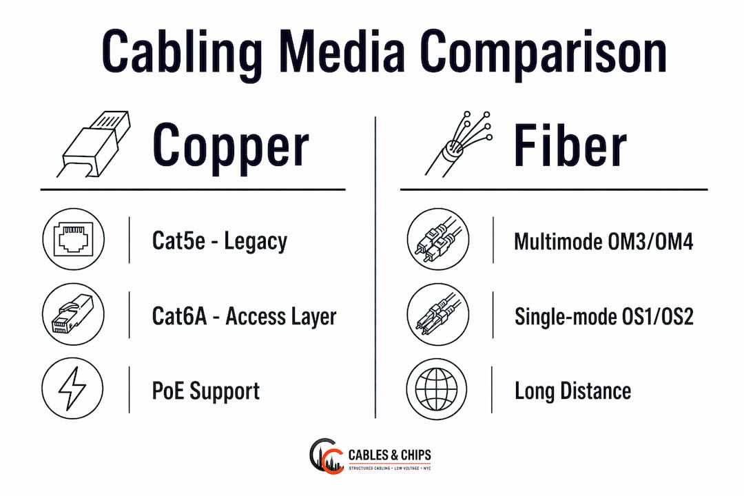
Cat5e supports 1G up to 100 meters and is largely legacy at this point. Cat6 handles 1G reliably and 10G up to 55 meters, making it a reasonable choice for short server links on a tight budget. Cat6A is the current standard for 10GBASE-T runs up to 100 meters and supports PoE++ without the thermal issues that plague Cat6 at higher power levels. Cat8 is a niche option for 25G and 40G over very short distances, primarily used for top-of-rack switch interconnects where twinax is not practical.

Copper’s key advantage at the access layer is PoE support. Fiber cannot carry electrical power, so any IP camera, wireless access point, or VoIP phone that draws power from the cable requires copper. 10GBASE-T PHY chips can draw 2–5 watts per port, compared to roughly 1 watt for a fiber transceiver, so power and cooling become real cost factors at scale.
Fiber: multimode OM3/OM4 and single-mode OS1/OS2
Multimode fiber (OM3/OM4) uses a 50-micron core with VCSEL light sources. OM4 supports 100G and 400G at shorter reaches, making it the standard choice for in-hall spine-to-leaf and aggregation links. OM3 is still serviceable for 10G and 40G but should not be specified for new builds targeting 100G and above.
Single-mode fiber (OS1/OS2) uses a 9-micron core with laser optics. OS2 is the low-loss variant and handles cross-building, campus, and long-haul links spanning several kilometers with the right transceivers. The fiber itself is inexpensive; the laser optics cost more than multimode transceivers, so single-mode is reserved for spans that genuinely need the reach. Practitioners recommend copper for runs under 100 meters, multimode for up to ~400 meters for high-speed intra-hall links, and single-mode for campus or long-haul connections.
Twinax and direct-attach copper (DAC)
Twinax DAC cables are the lowest-cost option for 10G, 25G, 40G, and 100G links under 5–7 meters, typically switch-to-switch or switch-to-server within the same rack or adjacent racks. They require no optics, consume minimal power, and are hot-swappable via SFP+, QSFP+, or QSFP28 interfaces.
Connector types
| Connector | Media | Typical use |
|---|---|---|
| RJ45 | Copper (Cat5e–Cat8) | Server access, PoE devices, copper patch panels |
| LC | Single-mode and multimode fiber | Standard patching on SFP/SFP+ ports |
| MPO/MTP | Multimode and single-mode fiber | High-density trunk cables, pre-terminated cassettes |
| QSFP (module, not connector) | Fiber or DAC | 40G/100G/400G spine and aggregation links |
MPO/MTP connectors carry 8, 12, or 24 fibers in a single ferrule, which is why they dominate high-density backbone trunks. Polarity and key orientation must be verified at installation; a reversed MPO trunk is one of the most common causes of a link that will not come up.
A hybrid design using copper at the access layer and multimode or single-mode fiber for aggregation and backbone is the dominant practical pattern in modern data centers.
Why structured cabling beats point-to-point wiring every time
Structured cabling centralizes fixed plant in distribution areas, allowing any change to be made by swapping a patch cord rather than re-routing a fixed run. The alternative, point-to-point wiring that connects devices directly, creates the “spaghetti” conditions that block airflow, make troubleshooting slow, and turn every network change into a physical construction project.
The three distribution areas defined by TIA-942 are:
- MDA (Main Distribution Area): the core of the cabling hierarchy, housing core switches and primary cross-connects
- HDA (Horizontal Distribution Area): connects MDA to server racks via horizontal cabling; typically one per row or zone
- IDA (Intermediate Distribution Area): an optional intermediate tier for very large halls, sitting between MDA and HDA
Structured cabling is not just about organization. When fixed plant terminates in a centralized distribution area, a single technician can reconfigure hundreds of connections in minutes using patch cords. The same change in a point-to-point environment requires tracing, labeling, and re-routing physical cable runs, often under live load. That difference in serviceability compounds every time the network grows.
Benefits of the structured approach include faster troubleshooting, predictable airflow through cable trays, cleaner documentation, and the ability to add capacity without touching the fixed plant. For more on structured cabling architecture, the principles apply equally to server rooms and full-scale data halls.
Which standards govern data center cabling compliance?
Two standards families define the rules: TIA-942 covers the full data center infrastructure, and TIA/EIA-568 governs the cabling components and performance within it. ISO/IEC 11801 is the international equivalent of TIA/EIA-568 and is referenced in global colocation contracts.
TIA-942-C, released in April 2024, is the current revision. It adds guidance for AI-driven density increases, thermal management, liquid immersion cooling, and edge data center requirements. For cabling specifically, it addresses pathway capacity, firestopping, labeling, and cabinet sizing.
TIA-942 defines four ratings for reliability and resiliency, and a certification program that enables independent review of conformity. A third-party TIA-942 audit is increasingly required by colocation tenants and enterprise customers as a condition of contract.
Trust signals stakeholders expect to see:
- Certified installers with BICSI credentials (RCDD, DCDC, or equivalent)
- As-built drawings that reflect the installed plant, not the design intent
- Test reports showing pass/fail to the stated standard with loss budgets
- Third-party TIA-942 audit or certification for Tier-rated facilities
- Firestopping documentation for all penetrations through fire-rated assemblies
TIA standards compliance is not a checkbox exercise. It is the documented proof that the plant performs as specified and that future changes can be made predictably.
Design tradeoffs every IT team should evaluate before building
Scalability and fiber headroom
Plan for 100G, 400G, and 800G optics from day one, even if you are deploying 10G or 25G today. The fiber plant is inexpensive per meter; the cost of pulling new cable through a congested pathway later is not. Install MPO trunk infrastructure with spare fiber counts and leave conduit capacity for future pulls.
Cabinet sizing and density
TIA-942-C recommends a minimum 800mm cabinet width in functional switch areas (MDA, HDA, and IDA) to accommodate higher-density cabling without obstructing airflow. Undersized cabinets are one of the most common retrofit problems in existing data halls.
Redundancy and path diversity
Diverse physical routes for primary and secondary paths are a requirement for any Tier 3 or Tier 4 design. Cables serving redundant systems must travel through separate conduits and separate pathways, not just separate ports on the same switch.
Power and cooling interactions
Copper PHYs draw more power per port than fiber transceivers, which matters when you are running hundreds of 10GBASE-T ports. At that scale, the difference in power draw affects both the electrical budget and the cooling load. CAT6A vs fiber decisions at the access layer should include a per-port power calculation, not just a cable cost comparison.
Pro Tip: Define a clear growth horizon of 3–7 years before finalizing media choices and pathway sizes. A data hall designed for today’s density will need a forklift upgrade in three years if pathway fill ratios exceed 40% at commissioning.
Cable management and installation best practices
Good cable management is what separates a serviceable plant from a liability. These practices apply whether you are building new or cleaning up an existing installation.
Pathway and separation rules
- Route copper and fiber in separate trays where possible; never bundle them with power cables
- Maintain a minimum 12-inch separation from unshielded power runs (or follow NEC Article 800 for your jurisdiction)
- Use ladder rack for heavy copper bundles; use enclosed trays for fiber to protect against bend damage
- Fill pathways to no more than 40% capacity to allow for future adds and adequate airflow
Labeling and documentation
Every cable needs a unique identifier at both ends. Labels must be machine-printed, not handwritten, and must match the as-built drawings. As-built documentation should be delivered in both PDF and editable format at project closeout.
Physical best practices
- Maintain manufacturer-specified bend radius (typically 4x the cable diameter for copper, 10x for fiber)
- Use hook-and-loop fasteners, not zip ties, for fiber bundles to avoid crush damage
- Leave adequate slack at patch panels and equipment for future moves without re-termination
- Route cables for airflow, not convenience — cables blocking hot-aisle/cold-aisle separation defeat cooling design
Firestopping and cable jacket selection
All penetrations through fire-rated walls and floors must be sealed with listed firestop systems. Plenum-rated (CMP) cable is required in air-handling spaces; riser-rated (CMR) is the minimum for vertical runs in non-plenum shafts. Using the wrong jacket type is a code violation and a liability in the event of a fire. Electrical safety considerations for cabling installations include proper jacket selection, grounding, and separation from high-voltage systems.
Installation checklist
- Pre-installation survey: confirm pathways, measure runs, identify conflicts with power and mechanical systems
- Staging: label all cable reels and pre-cut lengths before pulling
- Pull and route: follow pathway plans, maintain bend radius, avoid kinks
- Terminate and dress: punch down or terminate connectors, dress cables neatly at panels
- Test: certify all copper links, measure fiber insertion loss, run OTDR on single-mode spans
- Document and clean up: deliver as-built drawings, test reports, and remove all debris
Testing and validation: what to require at handover
Testing is not optional. A cable plant that has not been certified to its stated standard is an unverified assumption. Owners should require test reports showing pass/fail to the stated standard, loss budgets, and OTDR or insertion-loss results for single-mode spans.
Required test types:
- Copper certification: full channel or permanent link test using a Fluke DSX or equivalent Level IV tester, certified to TIA/EIA-568 for the installed category
- Fiber insertion loss: measured with a calibrated light source and power meter (LSPM) per TIA-526-14 or TIA-526-7
- OTDR traces: required for all single-mode spans to identify splice loss, connector reflectance, and fiber faults
- Polarity and continuity: verified on all MPO/MTP trunk assemblies before patching
Typical acceptance values
| Link type | Standard | Max insertion loss / pass criteria |
|---|---|---|
| Cat6A permanent link | TIA/EIA-568-C.2 | Pass to Cat6A channel at 500 MHz |
| Cat6A 10GBASE-T channel | TIA/EIA-568 | 100m max, full channel certification |
| OM4 multimode (100G) | TIA-526-14 | ≤1.5 dB per mated connector pair |
| OS2 single-mode span | TIA-526-7 | Per loss budget; OTDR trace required |
Level II testing (OTDR) is required for single-mode spans and any multimode link where a splice is present. Level I (insertion loss only) is acceptable for short multimode patch runs within a cabinet.
How much does data center cabling cost, and how long does it take?
Cost is driven by four factors: media choice, connectorization and transceivers, labor and testing, and pathway infrastructure. Fiber plant is inexpensive per meter; transceivers and optics are where recurring costs accumulate, particularly at 100G and above where QSFP28 modules carry a meaningful per-port cost.
Major cost drivers:
- Media: fiber cable is cheap; copper Cat6A is moderate; DAC twinax is low cost for short links
- Transceivers: QSFP28 (100G) and QSFP-DD (400G) optics dominate the bill of materials for spine layers
- Labor and testing: termination, certification testing, and documentation typically represent 40–60% of total project cost
- Pathway infrastructure: ladder rack, conduit, cable trays, and firestopping materials
- Documentation: as-built drawings and test report packages add time but are non-negotiable deliverables
Typical project phases for a medium-sized data hall
- Survey and design (1–2 weeks): site walk, pathway mapping, bill of materials, and drawing set
- Procurement (1–3 weeks): lead times for fiber, copper, patch panels, and transceivers
- Rough-in and pathways (1–2 weeks): install ladder rack, conduit, and cable trays
- Termination and patching (2–6 weeks): pull cable, terminate, dress, and label
- Testing and documentation (1–2 weeks): certify copper, test fiber, compile as-built package
- Final remediation (3–5 days): address test failures, re-label discrepancies, final walkthrough
Network infrastructure renovation projects that skip the survey phase consistently run over budget and over schedule.
Three pillars that make data center cabling work
Successful data center cabling rests on three pillars: structure, stability, and standardization. Structure means a hierarchical architecture (MDA/HDA/IDA) with centralized patching. Stability means physical plant that stays put, with proper support, bend radius management, and no ad-hoc adds that bypass the design. Standardization means every component, test, and label follows a documented specification that any qualified technician can read and work from.
Fiber versus copper is not a binary choice. Copper retains real advantages at the access layer: auto-negotiation, PoE support, and lower upfront cost per port. Fiber is the right answer for spine, backbone, and any run over 100 meters. The practical rules of thumb:
- Cat6A: server-to-ToR switch links under 100 meters, PoE devices
- Cat8: very short 25G/40G top-of-rack interconnects (under 30 meters)
- OM4 multimode: in-hall 100G/400G aggregation and spine links up to ~150 meters
- OS2 single-mode: cross-building, campus backbone, and any link requiring more than ~400 meters
Pro Tip: Hybrid designs work well in practice, but test the chosen mix under expected load before commissioning. Thermal behavior of dense copper bundles in high-fill trays can surprise even experienced teams, and a single congested tray can undermine an otherwise well-designed cooling layout.
Quick-reference glossary
- Cat5e: Category 5 enhanced copper; 1G to 100m; largely legacy
- Cat6: Category 6 copper; 1G to 100m, 10G to 55m
- Cat6A: Category 6A copper; 10G to 100m; current access-layer standard
- Cat8: Category 8 copper; 25G/40G to 30m; top-of-rack niche
- OM3/OM4: Optical Multimode grades 3 and 4; 50-micron multimode fiber for in-hall high-speed links
- OS1/OS2: Optical Single-mode grades 1 and 2; 9-micron fiber for long-reach and campus links
- LC connector: Small-form-factor fiber connector; standard for SFP/SFP+ ports
- MPO/MTP connector: Multi-fiber push-on connector; carries 8–24 fibers; used for high-density trunks
- MDA: Main Distribution Area; core of the TIA-942 cabling hierarchy
- HDA: Horizontal Distribution Area; connects MDA to server rows
- IDA: Intermediate Distribution Area; optional tier between MDA and HDA in large halls
- PoE: Power over Ethernet; delivers DC power over copper pairs alongside data
- OTDR: Optical Time-Domain Reflectometer; tests fiber spans for faults, splice loss, and connector reflectance
- Insertion loss: The reduction in optical power through a fiber link; measured in dB; lower is better
Key Takeaways
Correct data center cabling requires a structured architecture, standards-compliant media selection, certified testing, and complete as-built documentation delivered at project closeout.
| Point | Details |
|---|---|
| Audit and document first | Map every run and verify TIA-942 and TIA/EIA-568 compliance before any upgrade or expansion. |
| Match media to layer | Use Cat6A for access/PoE links under typical maximum copper distance, OM4 for in-hall 100G/400G, and OS2 for campus backbone. |
| Require test reports at handover | Copper certification, fiber insertion loss, and OTDR traces are non-negotiable deliverables. |
| Size pathways for growth | Keep pathway fill below 40% at commissioning; plan for 3–7 years of density growth. |
| Cables and Chips | Cables and Chips provides structured cabling, Cat6A installation, fiber backbone, testing, and as-built documentation for data centers in New York City. |
The cabling decisions most teams get wrong
The most persistent mistake in data center cabling is not choosing the wrong media. It is treating the cable plant as an afterthought until something breaks. Teams spend months selecting servers, switches, and software, then hand the cabling to whoever is available and cheapest. The result is an undocumented plant with no test reports, unlabeled runs, and pathways filled to capacity on day one.
The second mistake is over-specifying fiber everywhere to look future-proof, then discovering that the access layer has no PoE budget because copper was cut. Fiber is not universally better. It is better for the layers where distance and bandwidth demand it. Copper is better where power delivery and cost efficiency matter more than raw speed.
The third mistake is skipping as-built documentation. A cable plant without accurate drawings is not an asset. It is a liability that grows more expensive to manage every year. Every project should deliver a complete, verified as-built package before the final invoice is paid.
The teams that get this right treat cabling as infrastructure, not consumable. They specify standards, require certified installers, demand test reports, and plan for growth. The network is only as reliable as the physical layer underneath it.
Cables and Chips handles data center cabling from design to documentation
Cables and Chips brings more than 40 years of low-voltage contracting experience to data center cabling projects across New York City. The team handles the full scope: structured cabling system design, Cat6A and Cat6 installation, fiber optic infrastructure including backbone termination and testing, server rack setup, cable cleanup, and complete as-built documentation with certified test reports.

Every project includes TIA-942 and TIA/EIA-568 compliance guidance, OTDR and insertion-loss testing, and a full as-built package delivered at closeout. Whether you are building a new data hall, auditing an existing plant, or planning a density upgrade, Cables and Chips can scope the work, pull the permits, and deliver a tested, documented installation. Schedule a site survey at cables.nyc/services to get started.
Useful sources
Authoritative references for data center cabling specifications, standards, and design guidance:
- ANSI/TIA-942-C Standard: The current revision of the primary data center infrastructure standard, covering cabling, power, cooling, architecture, and the four-tier rating system. Required reading for any compliance or certification project.
- TIA-942 Certification Program: Details the independent certification process and what each of the four ratings requires. Use this to scope third-party audit requirements.
- TIA-942-C White Paper: Summarizes the key changes in the C revision, including the 800mm cabinet width recommendation and AI-density guidance.
- Commscope Data Center Cabling Design Fundamentals: Practical white paper covering structured cabling architecture, distribution area design, and test deliverable requirements.
- ISO/IEC 11801: The international generic cabling standard referenced in global colocation contracts and cross-border data center projects.
The most reliable data centers are not the ones with the most expensive equipment. They are the ones where every cable is documented, tested, and installed to a standard that any qualified technician can verify and work from.
FAQ
What is cabling in a data center?
Data center cabling is the physical layer of copper and fiber cables that connects servers, switches, storage systems, PDUs, and facility sensors. It forms the foundation of every network path and facility system in the building.
What kind of cable do data centers use?
Data centers use Cat6A copper for access-layer and PoE links, multimode fiber (OM3/OM4) for high-speed in-hall aggregation and spine links, and single-mode fiber (OS1/OS2) for cross-building and campus backbone runs. Twinax direct-attach copper is common for very short 10G–100G switch interconnects.
Is data center cabling a good career?
Structured cabling and data center infrastructure installation is a skilled trade with consistent demand, particularly for technicians with BICSI credentials (RCDD or DCDC) and experience with fiber termination, OTDR testing, and TIA-942 compliance documentation.
Why does proper data center cabling matter for uptime?
A documented, standards-compliant cable plant reduces troubleshooting time, supports predictable changes via patch cord reconfiguration, and eliminates the airflow problems caused by unmanaged point-to-point wiring. Those factors directly affect mean time to repair and overall facility availability.