
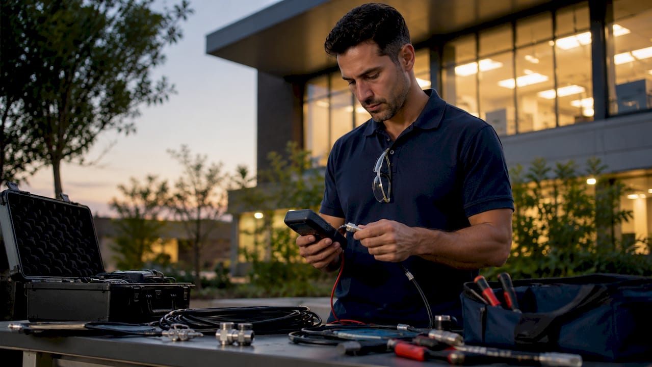
Cable continuity testing is the process of confirming that each conductor in a cable assembly carries an unbroken electrical path from one end to the other. Without this verification, opens, shorts, and miswires go undetected until they cause network failures. For technicians and engineers in commercial and industrial settings, understanding what is cable continuity testing is the foundation of every reliable cabling installation. The test uses low voltage (3–5V) and checks resistance against a pass threshold typically below 1 ohm, making it fast, safe, and non-destructive.
What is cable continuity testing and why does it matter?
Cable continuity testing is defined as a verification method that confirms each conductor in a cable has a complete, uninterrupted electrical path with no opens or shorts. The industry term for this check is a continuity test, and it sits at the base of every structured cable diagnostic workflow. A failed continuity test means the signal has no path to travel. That translates directly to a dead port, a dropped connection, or a security camera that never comes online.
The test is non-destructive. It applies only 3–5V across the conductor, so it cannot damage insulation or connected equipment. Typical pass thresholds require resistance below 1 ohm for a clean conductor. This makes continuity testing the correct first step before any higher-voltage diagnostic is applied to a cable run.
The importance of cable continuity extends beyond simple fault detection. Documented test results create a baseline record for the cable plant. When a fault appears six months after installation, that record tells you whether the cable passed at commissioning or arrived defective. That distinction saves hours of troubleshooting in a live commercial environment.
How to test cable continuity with a multimeter
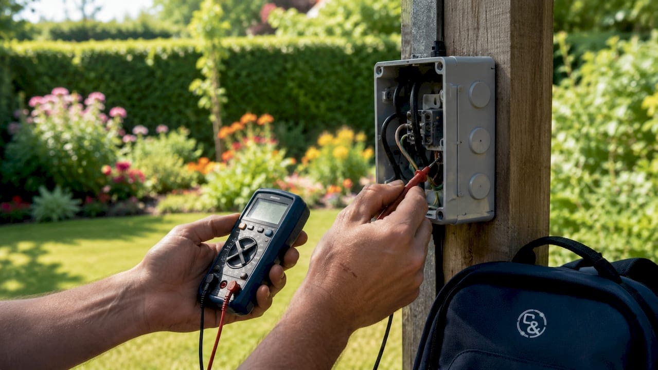
A digital multimeter is the standard tool for continuity testing in the field. The continuity mode is marked with a speaker or diode symbol on the dial. The procedure is straightforward, but each step must be followed in order to produce reliable results.
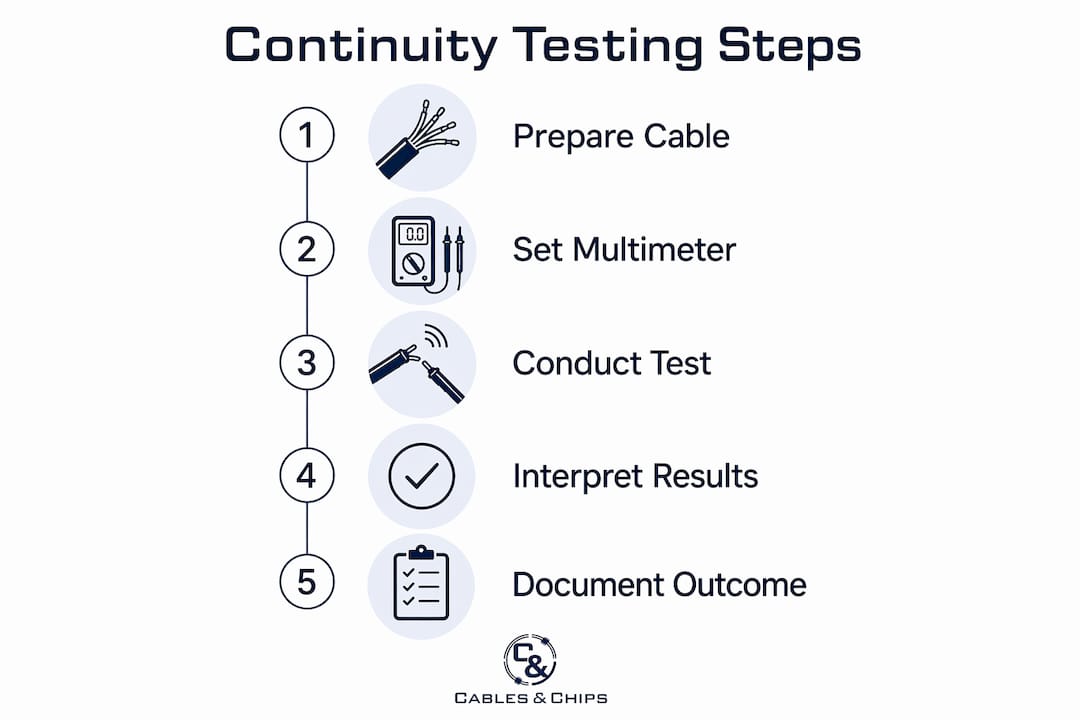
- De-energize the circuit. Verify the cable is completely powered down. Testing on live circuits risks damaging the meter, blowing its fuse, and causing personal injury. Use a non-contact voltage tester to confirm zero voltage before touching any conductor.
- Set the multimeter to continuity mode. Rotate the dial to the speaker or diode symbol. Insert the red probe into the VΩ port and the black probe into the COM port.
- Probe each conductor end-to-end. Place one probe on the conductor at one end of the cable and the other probe on the matching conductor at the far end. For a Cat6 cable, this means testing each of the eight conductors individually.
- Interpret the result. An audible beep confirms continuity. No beep means an open circuit. The audible beep indicates resistance below the meter’s threshold, commonly 30–50 ohms, though near-zero ohms is the target for a clean conductor.
- Check for shorts. Probe between two separate conductors. A beep here signals an unintended short or miswire that will cause network errors or equipment damage.
- Work systematically through multi-conductor cables. Each conductor test takes approximately 5 seconds. A structured pin-by-pin approach prevents skipped conductors and missed miswires.
Pro Tip: Label each conductor pair before testing a multi-conductor cable. Systematic labeling eliminates the most common source of missed faults: testing the wrong pair twice and skipping another entirely.
What does continuity testing confirm, and what are its limits?
Continuity testing confirms one thing with certainty: a complete electrical path exists through the conductor being tested. It also detects shorts between conductors and identifies miswires where conductors are connected to the wrong pins. These are the three most common installation faults, and continuity testing catches all of them quickly.
The limitations are equally important to understand. A passing continuity test does not certify cable quality or performance. A conductor that is nearly broken, held together by a few strands, can still pass the beep test under zero load. Under real network traffic, that conductor fails intermittently and creates faults that are extremely difficult to trace.
Continuity testing also cannot detect:
- Insulation breakdown. Degraded insulation between conductors may not create a measurable short at 3–5V but will fail under higher operating voltages.
- High-resistance faults. A multimeter beep threshold of 30–50 ohms means a connection with 20 ohms of resistance still passes, even though it will degrade signal quality in use.
- Split pairs. A wiring error where conductors from different pairs are swapped passes continuity but destroys high-frequency data transmission on Cat6 and Cat6A cables.
- Signal performance metrics. Crosstalk, attenuation, and return loss require certification-grade testing with tools like a Fluke DSX CableAnalyzer, not a multimeter.
Continuity testing is a screening test, not a quality test. It rules out basic wiring faults fast. It does not confirm the cable will perform under real network conditions.
How does continuity testing compare to other cable testing methods?
Continuity testing is the first step in a structured test sequence, not a standalone certification. Understanding where it fits relative to insulation resistance testing, hipot testing, and performance certification prevents both under-testing and equipment damage.
Pro Tip: Always run continuity testing before insulation resistance or hipot tests. Applying high voltage to a miswired cable can destroy test equipment and damage the cable permanently. Continuity first is a safety rule, not just a workflow preference.
| Test Method | Voltage Applied | What It Checks | Typical Use Case |
|---|---|---|---|
| Continuity testing | 3–5V | Opens, shorts, miswires | All cable types, first step |
| Insulation resistance | 500V DC | Insulation quality between conductors | Power and control cables |
| Hipot (dielectric) | 500–2,100V AC/DC | Dielectric strength, insulation breakdown | Critical power and safety circuits |
| Performance certification | High-frequency signal | Crosstalk, attenuation, return loss | Cat6, Cat6A, fiber optic data cables |
Insulation resistance testing applies 500V DC across the insulation between conductors. It detects degraded insulation that continuity testing cannot see. Hipot testing goes further, stressing dielectric strength at 500–2,100V to verify the cable will not fail under peak operating voltage. Neither test should be applied to a cable with an unresolved continuity fault.
Performance certification for data cables like Cat6 and Cat6A goes beyond all three. Tools like the Fluke DSX CableAnalyzer measure insertion loss, near-end crosstalk (NEXT), and return loss against TIA-568 standards. A cable can pass continuity and still fail certification. For commercial network installations, testing Cat6 after installation requires both continuity verification and full performance certification to meet warranty and compliance requirements.
Best practices for reliable continuity testing results
The difference between a professional continuity test and a careless one is documentation and discipline. Getting a beep is not enough in a commercial or industrial environment.
- Verify de-energized state first. A non-contact voltage tester confirms zero voltage before probing. Testing on energized circuits damages meters and creates shock hazards. This step is non-negotiable.
- Use resistance mode on suspicious conductors. If a conductor beeps but the network port behaves erratically, switch the multimeter to resistance mode. A reading above 1–2 ohms on a short cable run signals a high-resistance joint that the beep test missed.
- Document every result. Record pass/fail for each conductor, the cable ID, and the date. This creates the baseline record that makes future troubleshooting faster and supports quality control on large installations.
- Test for shorts between all conductor pairs. Probe between each pair combination, not just end-to-end. A miswire that creates a short between pin 3 and pin 6 on a Cat6 cable will not show up in an end-to-end test of either conductor alone.
- Follow a structured test methodology. Systematic pin-by-pin verification prevents the most common field error: random probing that misses faults and produces false confidence.
Pro Tip: For large multi-conductor cable runs, use a dedicated cable tester like the Fluke MicroScanner or Ideal Networks LanTEK rather than a standard multimeter. These tools automate pin-by-pin verification and generate printed test reports, which are required for most commercial project sign-offs.
The most overlooked pitfall is the false positive from a nearly broken strand. A conductor held together by minimal contact passes the beep test at rest. Under the mechanical stress of cable management or thermal cycling in a server room, that strand separates and the fault appears. Resistance mode measurement and physical inspection of terminations catch these before they become live network problems.
Key Takeaways
Cable continuity testing is a non-destructive screening test that confirms unbroken electrical paths and must always precede insulation resistance or hipot testing in any structured cable diagnostic workflow.
| Point | Details |
|---|---|
| Definition | Continuity testing verifies each conductor has a complete, uninterrupted electrical path with no opens or shorts. |
| Test sequence | Always perform continuity testing first to prevent high-voltage damage to miswired or shorted cables. |
| Limitations | A passing beep does not confirm insulation quality, signal performance, or the absence of high-resistance faults. |
| Documentation | Record pass/fail results for every conductor to support quality control and future troubleshooting. |
| Beyond continuity | Cat6 and Cat6A cables require full performance certification after continuity passes for network-grade reliability. |
Why continuity testing is the step most teams rush past
After more than 40 years working on commercial network infrastructure in New York City, I have seen the same pattern repeat itself on large installations. The pressure to finish a job fast pushes technicians to skip systematic continuity verification or treat a single end-to-end beep as a complete sign-off. That shortcut costs far more time later.
The most expensive network fault I have encountered was traced to a miswired pair in a 48-port patch panel that passed a casual continuity check. The installer tested end-to-end on each conductor but never probed for shorts between conductors. The miswire created a short under load that took two days to isolate across a 200-run cable plant. A 10-minute systematic short test at installation would have caught it immediately.
My advice to every technician is this: treat continuity testing as a protocol, not a task. Follow the same sequence on every cable, every time. Document the results even when the job is small. The cable testing certification workflow we use at Cables integrates continuity as the mandatory first gate before any performance testing begins. That structure is what separates a documented, warrantable installation from one that creates problems six months after the crew leaves.
Continuity testing alone will not certify a network. But skipping it or rushing it guarantees that the more expensive tests that follow are built on an unverified foundation.
— Ken
Professional cable testing services for commercial networks
Cables & Chips brings more than 40 years of structured cabling experience to commercial offices, server rooms, and enterprise environments across New York City. Every installation we complete includes documented continuity verification as the first step in a full testing and certification workflow.

Whether you are commissioning a new Cat6A installation, troubleshooting an existing cable plant, or building out a new MDF/IDF room, our team delivers tested, documented, and certified infrastructure. We cover everything from structured cabling components and patch panel termination to full performance certification. Contact Cables & Chips at 20 Vesey Street, Lower Manhattan, to schedule a site survey and get your network infrastructure documented correctly from day one.
FAQ
What is cable continuity testing in simple terms?
Cable continuity testing confirms that each conductor in a cable has a complete, unbroken electrical path from one end to the other. It detects opens, shorts, and miswires using a low voltage (3–5V) signal through a multimeter or dedicated cable tester.
What is a continuity tester and how does it work?
A continuity tester is a device, typically a digital multimeter set to continuity mode, that applies a small voltage across a conductor and signals with an audible beep when the circuit is complete. The beep triggers when resistance falls below the meter’s threshold, commonly 30–50 ohms.
Can continuity testing replace full cable certification?
No. Continuity testing confirms basic wiring integrity but cannot measure insulation quality, crosstalk, attenuation, or return loss. Data cables like Cat6 and Cat6A require performance certification testing with tools like a Fluke DSX CableAnalyzer to meet TIA-568 standards.
Why must cables be de-energized before continuity testing?
Testing continuity on a live circuit damages the multimeter, blows its internal fuse, and creates a serious shock hazard for the technician. Always confirm zero voltage with a non-contact voltage tester before probing any conductor.
What faults does continuity testing miss?
Continuity testing does not detect insulation breakdown, high-resistance joints above the meter’s beep threshold, split pairs, or any signal performance degradation. A cable can pass continuity and still fail under real network load, which is why continuity is a screening step, not a final sign-off.