
A structured cabling system is defined as a standardized telecommunications infrastructure organized into six discrete subsystems, each governed by ANSI/TIA-568.1-D for commercial buildings. These structured cabling system components include Entrance Facilities, Equipment Rooms, Backbone Cabling, Telecommunications Rooms, Horizontal Cabling, and Work Area components. Together, they create a modular, vendor-neutral network that supports voice, data, video, and building automation systems. Understanding each subsystem is the foundation of any reliable cabling infrastructure design. Your network is only as strong as the infrastructure behind it.
What are the six major structured cabling system components?
The six subsystems defined by ANSI/TIA-568.1-D are not arbitrary categories. They represent a logical architecture that separates function, performance requirements, and physical placement. Mapping your physical components directly to these subsystems prevents specification gaps and keeps your design aligned with performance rules from day one.
-
Entrance Facilities (EF): The Entrance Facility is where the public network meets your private building infrastructure. It houses the demarcation point between the service provider and the building owner, along with protective devices, connecting hardware, and any necessary conversion equipment. In a Manhattan high-rise, this is typically a dedicated room or closet on the ground floor where carrier fiber or copper enters the building.
-
Equipment Rooms (ER): Equipment Rooms serve as the centralized hub for core networking hardware, including main distribution frames (MDF), servers, PBX systems, and enterprise-grade switches. Unlike a standard telecommunications closet, an ER supports more complex and larger equipment. Proper equipment room organization directly affects how quickly your team can respond to faults and perform upgrades.
-
Backbone Cabling: Backbone cabling connects the Entrance Facility, Equipment Rooms, and Telecommunications Rooms using high-capacity fiber optic or copper cables. It carries the highest data volumes in the system and typically runs vertically between floors or horizontally between buildings in a campus environment. Fiber optic is the standard choice for backbone runs due to its distance capability and bandwidth capacity.
-
Telecommunications Rooms (TR): Telecommunications Rooms are intermediate distribution points where backbone cabling terminates and horizontal cabling begins. They house patch panels, switches, and cross-connect hardware. A well-designed TR is not a storage closet. It is an operational hub that enables patching flexibility and makes moves, adds, and changes fast and non-disruptive.
-
Horizontal Cabling: Horizontal cabling runs from the TR to individual work area outlets. It uses twisted-pair copper cables such as CAT6 or CAT6A, or multimode fiber in high-performance environments. This subsystem delivers connectivity to every desk, conference room, and access point in your facility.
-
Work Area (WA): The Work Area includes everything between the wall outlet and the end device: faceplates, modular jacks, patch cords, and adapters. These components are the most frequently touched parts of the system, so quality and compatibility with the horizontal cabling category matter significantly.
Pro Tip: Label every patch panel port, outlet, and cable run during installation. Retroactive labeling costs far more in labor than doing it right the first time, and undocumented systems are the leading cause of unnecessary downtime during moves and changes.
How do backbone cabling and horizontal cabling differ?

Backbone and horizontal cabling serve fundamentally different roles in a structured cabling system, and confusing them during the design phase leads to performance failures and costly rework.
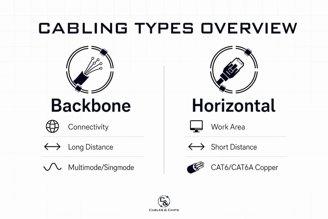
| Feature | Backbone cabling | Horizontal cabling |
|---|---|---|
| Primary function | Connects EF, ER, and TRs | Connects TRs to work area outlets |
| Typical cable types | Single-mode fiber, multimode fiber, large-pair copper | CAT6, CAT6A, multimode fiber |
| Maximum run length | Varies by cable type and application | 90-meter permanent link, 100-meter channel |
| Traffic volume | High-capacity, aggregated traffic | Individual device-level traffic |
| Replacement frequency | Infrequent, long-term investment | More frequent due to office reconfigurations |
| Cost per run | Higher due to fiber and longer distances | Lower per run, but higher total count |
The 90-meter permanent-link limit for horizontal cabling is one of the most consequential constraints in structured cabling design. Exceeding it causes signal attenuation that degrades throughput and increases error rates. This limit is defined by both ISO/IEC 11801 and ANSI/TIA standards, and it directly determines where your Telecommunications Rooms must be physically located within a floor plan.
Backbone cabling does not carry the same fixed-length ceiling, but its design is governed by the application. A 10 Gigabit Ethernet run over OM4 multimode fiber supports up to 400 meters. Single-mode fiber extends that to kilometers, making it the right choice for campus or multi-building environments. For a deeper comparison of CAT6A versus fiber optic options for your specific project, the CAT6A vs. fiber decision guide from Cables covers the tradeoffs in detail.
Pro Tip: Never use horizontal cabling cable types for backbone runs. CAT6 and CAT6A are engineered for short, high-density horizontal segments. Using them as backbone substitutes introduces performance risk and makes future upgrades more complicated.
What performance standards apply to structured cabling components?
Two standards govern the performance requirements for structured cabling system components in commercial environments: ANSI/TIA-568.1-D for North America and ISO/IEC 11801 internationally. Both define the same six-subsystem architecture and set consistent performance thresholds, which means a system designed to one standard is broadly compliant with the other.
The critical performance parameters IT managers need to understand include:
- Insertion loss (attenuation): The maximum signal loss allowed across a cabling channel. CAT6 channels must meet specific attenuation limits at frequencies up to 250 MHz. CAT6A extends this to 500 MHz, supporting 10GBASE-T applications.
- Return loss: Measures signal reflection caused by impedance mismatches. Poor connector terminations are the most common cause of return loss failures.
- NEXT (Near-End Crosstalk): Measures interference between adjacent cable pairs. CAT6A’s improved shielding and geometry reduce NEXT significantly compared to CAT6.
- Channel length: The 100-meter channel maximum includes the 90-meter permanent link plus up to 10 meters of patch cords and equipment cords combined.
- Fiber optic testing: ISO/IEC 11801 mandates documented measurement procedures, connector inspections, and attenuation testing as part of the formal acceptance process for fiber installations.
Documentation is not optional in a compliant installation. Every cable run must be tested, and results must be recorded with a traceable identifier that matches the physical label on the cable. This documentation becomes the baseline for troubleshooting, warranty claims, and future upgrade planning. Facilities that skip this step consistently spend more on reactive maintenance than those that invest in proper certification at installation.
Structured cabling standards also require that modular components be selected to support moves, adds, and changes without disturbing permanent cabling runs. This is the core principle behind the patch panel and cross-connect architecture used in every compliant TR and ER.
Which mistakes should IT professionals avoid in cabling component planning?
Poor planning at the component level creates problems that compound over time. The following mistakes appear repeatedly in commercial cabling projects, and each one is avoidable with proper upfront design.
- Placing TRs based on user density instead of cable length limits. Cable length constraints determine TR placement more than headcount does. A floor plan with 40 users spread across 15,000 square feet may require two TRs to keep all horizontal runs within 90 meters. Discovering this during installation rather than design causes expensive rework.
- Skipping structured testing and certification. Running cable without certifying it with a Fluke Networks DSX CableAnalyzer or equivalent tool leaves you with no performance baseline. When issues arise, you have no data to isolate the fault.
- Using the wrong cable category for the application. CAT5e is not an acceptable substitute for CAT6 in new installations targeting 1 Gigabit or higher performance. CAT6 is not a substitute for CAT6A in 10G environments or runs over 55 meters.
- Ignoring backbone topology requirements. Backbone cabling must follow a star topology from the main Equipment Room to each TR. Daisy-chaining TRs creates single points of failure and violates ANSI/TIA-568.1-D topology requirements.
- Treating the Work Area as an afterthought. Patch cord quality and length matter. Cords that exceed the allowable equipment cord budget consume channel length that should be reserved for the permanent link. Non-standard or unrated patch cords degrade the entire channel’s performance.
Pro Tip: During design, draw your floor plan to scale and overlay the 90-meter radius from each proposed TR location. Every work area outlet must fall within that radius. This single exercise catches the majority of TR placement errors before a single cable is pulled.
Understanding how building cabling infrastructure works in a commercial context, particularly in dense urban environments like New York City, adds another layer of practical constraints that standard documents do not fully address.
Key takeaways
A structured cabling system built to ANSI/TIA-568.1-D requires six interdependent subsystems, and the performance of the entire network depends on correct design, component selection, and certified testing at every layer.
| Point | Details |
|---|---|
| Six defined subsystems | ANSI/TIA-568.1-D organizes all commercial cabling into EF, ER, Backbone, TR, Horizontal, and WA components. |
| 90-meter horizontal limit | Horizontal cabling permanent links cannot exceed 90 meters; this constraint drives TR placement decisions. |
| Backbone vs. horizontal distinction | Backbone uses fiber or large-pair copper for high-capacity runs; horizontal uses CAT6 or CAT6A for device-level connectivity. |
| Standards-based testing required | ISO/IEC 11801 mandates documented attenuation and connector testing for fiber; ANSI/TIA requires certification for copper. |
| Modularity enables scalability | Standards-based component selection supports moves, adds, and changes without disrupting permanent cabling infrastructure. |
What 40 years of cabling projects taught me about component planning
The single most underestimated component in any structured cabling project is the Telecommunications Room. Every IT manager I have worked with over the years focuses on cable category, port count, and switch specs. Almost none of them think hard enough about TR placement until they are standing on a job site watching a crew pull cable that is 15 meters too short to reach the patch panel.
The 90-meter rule is not a guideline. It is a hard physical constraint, and it should be the first thing you draw on your floor plan before you select a single piece of hardware. I have seen projects in Midtown Manhattan where a single TR was specified for an entire floor because the headcount was low. The floor was 22,000 square feet. The result was a complete redesign two weeks into installation, with costs that far exceeded what a second TR would have added to the original budget.
The other lesson I keep coming back to is documentation. A cabling system without a complete, labeled, tested record is not an asset. It is a liability. The facilities that call us for emergency troubleshooting are almost always the ones that skipped certification during installation. The facilities that handle moves and upgrades without drama are the ones where every run has a label, a test report, and a patch panel map.
Modular design is the third pillar. Scalable cabling infrastructure is not about over-building. It is about selecting components that can accommodate the next technology cycle without tearing out the permanent cabling. CAT6A installed today supports 10G now and positions you for 25G and 40G applications at the edge as those standards mature. That is not speculation. That is the documented performance headroom built into the standard.
— Ken
How Cables & Chips supports your cabling infrastructure in NYC
Cables & Chips designs and installs structured cabling systems for commercial offices, secure facilities, and enterprise environments across New York City. Whether you need CAT6 structured cabling for a new office build-out or a fiber optic backbone upgrade for a multi-floor facility, the team at Cables brings more than 40 years of hands-on experience to every project. Every installation is tested, certified, and fully documented. For larger-scale deployments, enterprise edge infrastructure considerations also factor into how backbone and equipment room components are specified. Contact Cables at 20 Vesey Street in Lower Manhattan to schedule a site survey.
FAQ
What are the six components of a structured cabling system?
The six components defined by ANSI/TIA-568.1-D are Entrance Facilities, Equipment Rooms, Backbone Cabling, Telecommunications Rooms, Horizontal Cabling, and Work Area. Each subsystem has a distinct function and performance specification within the overall network infrastructure.
What is the maximum length for horizontal cabling?
The permanent link for horizontal cabling is limited to 90 meters, with a maximum channel length of 100 meters including patch cords, per ISO/IEC 11801 and ANSI/TIA standards. Exceeding these limits causes signal attenuation that degrades network performance.
What cable types are used in structured cabling systems?
Horizontal cabling typically uses CAT6 or CAT6A twisted-pair copper, while backbone cabling uses multimode or single-mode fiber optic cable for high-capacity, longer-distance runs. The choice depends on required bandwidth, distance, and budget.
Why does telecommunications room placement matter so much?
TR placement is governed by the 90-meter horizontal cabling limit, not by user density. Placing TRs without accounting for cable run distances is one of the most common causes of costly redesigns during structured cabling installation.
Do structured cabling installations require testing and documentation?
Yes. ISO/IEC 11801 requires documented testing procedures including attenuation measurement and connector inspection for fiber optic installations, and ANSI/TIA standards require certification testing for copper channels. Undocumented systems create long-term maintenance and troubleshooting problems.