
Star Topology Cabling Explained for IT and Facilities Teams

TL;DR:
- Star topology cabling connects each device with a dedicated cable to a central switch or patch panel, simplifying troubleshooting and scalability. However, it risks creating a single point of failure and requires more cable, increasing upfront costs. Proper planning, certification, and redundancy measures ensure reliable and maintainable enterprise networks.
Star topology cabling is a physical wiring layout where every device gets its own dedicated cable run terminating at a central point: a switch, patch panel, or telecom room. For virtually any commercial or office deployment in the US, it is the right choice. Small offices benefit from its simplicity; enterprise and campus environments scale it into a hierarchical model with MDF and IDF rooms that the TIA/EIA-568 structured-cabling standard is built around.
Top three advantages:
- A single cable or device failure affects only that node, not the entire network
- Moves, adds, and changes are handled at the patch panel without touching permanent cabling
- Troubleshooting is faster because each run is isolated and testable end-to-end
Two real drawbacks:
- The central switch is a single point of failure without redundancy measures
- Home-run wiring requires more total cable than bus or ring layouts, raising upfront material and labor costs
Recommended next step: commission a site survey, develop a structured-cabling specification, and engage a certified installer before finalizing any bid.
What exactly is star topology cabling?
Star topology cabling means every work-area outlet connects back to a central termination point via its own dedicated cable, called a home run. Nothing is daisy-chained. Nothing is shared along a common trunk. Each device gets a private path to the network.
That description covers the physical topology. The logical topology is a separate question. As engineers note, physical star wiring can support multiple logical topologies depending on the active equipment and protocol in use. A hub creates a logical bus on a physical star; a managed switch creates a logical point-to-point connection to each port. Modern networks almost always pair physical star cabling with switched Ethernet, which is why the two concepts are often conflated.
Core terms you will encounter
| Term | What it means |
|---|---|
| MDF (Main Distribution Frame) | Central telecom room serving a building or campus; houses core switches and backbone terminations |
| IDF (Intermediate Distribution Frame) | Floor-level telecom room; houses access switches and horizontal patch panels |
| Patch panel | Passive termination block where horizontal cable runs land; enables cross-connects via patch cords |
| Home run | A single, uninterrupted cable from a work-area outlet to the patch panel |
| Cross-connect | The patch cord or jumper linking two termination points (e.g., patch panel port to switch port) |
| Access switch | The switch in the IDF that connects end devices to the network |
A simple star topology diagram shows a central room with a patch panel and switch, spokes radiating outward to wall outlets, and a single uplink leaving the room toward the MDF. That mental picture is the foundation for everything that follows.

How star cabling is actually implemented in a commercial project
Real-world star network cabling follows a structured path from the wall outlet to the core. Here is the wiring sequence used on commercial projects:
- Work-area outlet — A keystone jack mounted in a wall plate or floor box; this is where the user’s device plugs in.
- Horizontal cabling — The home-run cable (typically Cat6 or Cat6A) runs through conduit, cable tray, or J-hooks from the outlet to the IDF. Structured cabling standards cap the permanent horizontal copper channel length is limited by standards: the permanent horizontal copper link may not exceed 90 meters, and the full channel including patch cords is capped at 100 meters.
- Consolidation point (optional) — In open-office or modular furniture environments, a consolidation point can be installed in the ceiling or furniture raceway to allow flexible outlet repositioning without re-pulling cable to the IDF.
- IDF patch panel — The horizontal cable terminates on a patch panel in the IDF. This is where the permanent cabling ends. Practitioners separate permanent cabling from switch ports using patch cords so moves, adds, and changes never disturb the home runs.
- Access switch — A patch cord connects the patch panel port to the access switch in the same IDF rack.
- Backbone uplink — The IDF connects back to the MDF via backbone cabling (typically fiber) running through vertical pathways or inter-building conduit.
- MDF / core — The MDF houses the core or distribution switch, backbone patch panels, and any WAN or internet edge equipment.
For open-office builds, the planning considerations around outlet density and pathway capacity are worth reviewing before finalizing the design.
Which cable types work best in a star topology?
Copper and fiber each have a clear role. The table below covers the media most commonly specified for US commercial star cabling projects.
| Media | Typical max speed | Practical distance limit | Best use |
|---|---|---|---|
| Cat5e | 1 GbE | 100 m channel | Legacy or low-budget access |
| Cat6 | 1 GbE / 10 GbE short-reach | 100 m (1G); — (10G) | Standard office access |
| Cat6A | 10 GbE | 100 m channel | High-density access, PoE++ |
| OM3 multimode fiber | 10 GbE | ~300 m | IDF-to-MDF backbone, short campus |
| OM4 multimode fiber | 10 GbE / 40 GbE | ~550 m | Longer backbone runs |
| Single-mode fiber | 100 GbE+ | Kilometers | Campus backbone, inter-building |
Practical selection rule: Cat6 covers most standard office access needs. Cat6A is the better call for any run supporting PoE++ devices (access points, IP cameras, door controllers) or where 10 GbE to the desktop is on the roadmap. For fiber backbone design, OM4 handles most intra-building distances; single-mode is the right call for inter-building links or any run exceeding OM4’s limits.
One point that trips up many bids: every component in a channel must match the rated category. A Cat6A cable terminated with Cat6 jacks and tested against Cat6A performance limits will fail. The jack, patch cord, and cable must all be the same category, and the entire channel must be certified to that category’s standard.
What are the real advantages of star cabling?
The business case for star topology in commercial environments comes down to four concrete benefits.
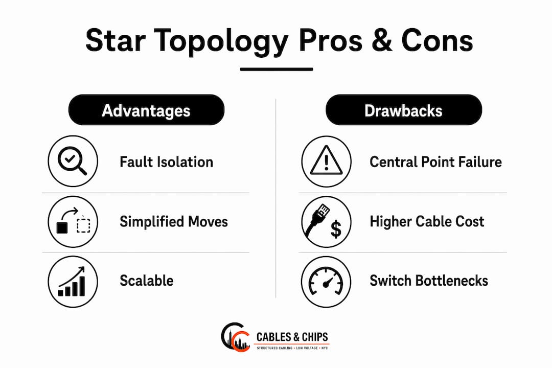
- Fault isolation. When a cable breaks or a NIC fails, only that node goes offline. On a bus topology, a single break can take down every device on the segment. On a star, the rest of the network keeps running while the technician swaps one patch cord or replaces one port.
- Faster troubleshooting. Switch port LEDs and management software immediately identify which port has lost link. A Fluke-style cable tester can then confirm whether the fault is in the patch cord, the jack, or the horizontal run, usually in minutes.
- Easier moves, adds, and changes. Reconfiguring a workstation means moving one patch cord on the patch panel. No cable re-pulls, no network downtime for other users. For facilities teams managing frequent tenant changes, that operational simplicity has real dollar value.
- Scalability and future-proofing. Adding a new outlet means pulling one new home run to the IDF. A physical star cabling plan also supports logical architecture changes — VLANs, routed cores, SD-WAN overlays — without touching the physical layer. The cabling you install today can support whatever switching and routing technology comes next.
The long-term operational savings from predictable MACs and faster troubleshooting often justify the higher upfront cable cost for commercial clients, particularly in multi-tenant buildings or facilities with active IT teams.
Drawbacks and failure modes to plan for
Star topology is not without risks. Understanding them upfront is what separates a well-designed installation from one that causes problems two years later.
Central point of failure. Every device on a star segment depends on the central switch. If that switch fails, the entire segment goes dark. Enterprises mitigate this with redundant switches, dual-homing, and failover protocols such as Spanning Tree Protocol (STP) or Link Aggregation Control Protocol (LACP). These add cost and design complexity, but for any environment where downtime is unacceptable, they are standard practice.
Higher upfront cabling cost. Star wiring requires more total cable than bus or ring designs because every device gets its own dedicated run. In a large floor plate with dozens of outlets, that adds up in both materials and labor. The trade-off is long-term maintainability, but the initial budget impact is real and should be reflected in RFPs.
Switch backplane bottlenecks. A 24-port Gigabit switch does not automatically deliver 24 Gbps of non-blocking throughput. Designers must verify that the switch’s backplane capacity matches the aggregate port potential, or specify uplink aggregation via LACP or EtherChannel to avoid the central switch becoming a performance bottleneck under load.
Installation mistakes that cause failures. Violated bend radius on Cat6A, inadequate slack at termination points, missing labels, and cable pileups in the IDF are the most common sources of post-installation problems. None of them show up on a visual inspection. They show up on a cable certification report, or worse, during a production outage.
Design and installation best practices
A clean star installation follows a disciplined sequence from planning through handover. Use this checklist when evaluating contractor proposals or briefing your team.
- Site survey first. Walk every pathway before pulling a single cable. Identify conduit capacity, ceiling obstructions, fire-rated barriers requiring firestopping, and distance from each outlet location to the IDF.
- Plan for growth. Size conduit and cable trays for at least 30% spare capacity. Specify spare ports on patch panels and switches. Retrofitting pathways after occupancy is expensive.
- Establish a labeling scheme before installation begins. Every outlet, patch panel port, and switch port should carry the same identifier. As-built documentation tied to those labels is what makes the system maintainable five years from now.
- Maintain bend radius and slack. Cat6A has a minimum bend radius of four times the cable diameter. Violating it degrades alien crosstalk performance. Leave at least 12 inches of slack at each termination point.
- Separate telecommunications cabling from power. Run data cables at least 12 inches from unshielded power conductors and cross at 90-degree angles where separation is not possible.
- Use patch panels and horizontal cable managers. Never connect horizontal runs directly to switch ports. The cross-connect model protects permanent cabling and keeps the IDF organized.
- Require certified test reports. Every link should be tested and certified to its rated category using a qualified tester. Test reports must be tied to port labels and delivered as part of the project closeout package.
- Confirm TIA/EIA-568 compliance in writing. Require the contractor to certify that the installation meets the current TIA/EIA-568 family of standards and specify the warranty period for both materials and workmanship.
Pro Tip: Require the contractor to deliver test files in the tester’s native format (e.g., .flw for Fluke DSX), not just printed PDFs. Native files can be re-analyzed later if a performance question arises.
Why the hierarchical star is the commercial standard
The hierarchical star model separates infrastructure into two layers: horizontal distribution (work area to IDF) and backbone (IDF to MDF). TIA/EIA-568 is built around this architecture, and for good reason. It keeps cable runs within testable distance limits, concentrates administration points in dedicated telecom rooms, and allows backbone upgrades without touching horizontal cabling.
TIA-568 limits backbone cross-connects to three or fewer in any cabling path. Exceeding that limit degrades signal integrity and complicates administration. The standard also caps horizontal copper channels at 90 meters of permanent link, with the full channel (including patch cords) not to exceed 100 meters. Backbone fiber distances depend on media: OM3 supports 10 GbE to approximately 300 meters, OM4 to approximately 550 meters, and single-mode fiber extends to kilometers for campus or inter-building links.
IDF placement follows a simple rule: no horizontal run should exceed the 90-meter permanent link limit. In practice, that means one IDF per floor in most commercial buildings, positioned near the geometric center of the floor plate. Large floor plates or buildings with irregular shapes may require two IDFs per floor. For campus environments, a two-level hierarchical star adds an intermediate distribution layer between building MDFs and a campus core, which is the standard model for multi-tenant and campus deployments.
How to test and certify a star-cabled network
Testing is not optional. A cable that looks clean and passes a basic continuity check can still fail insertion loss or NEXT limits under load. Here is what a proper certification process covers.
- Wiremap and continuity — Confirms all eight conductors are connected correctly, with no opens, shorts, or miswires (split pairs are a common termination error).
- Insertion loss — Measures signal attenuation across the channel. High attenuation usually points to excessive cable length, a bad termination, or a damaged connector.
- NEXT (Near-End Crosstalk) and FEXT (Far-End Crosstalk) — Measures interference between pairs. Failures here often trace back to untwisted pairs at termination points or violated bend radius.
- Return loss — Measures signal reflected back toward the source. Impedance mismatches from mixed-category components are the most common cause.
- Channel certification — A qualified tester (Fluke DSX series is the field standard) runs all of the above against the category’s performance limits and issues a pass/fail result per TIA/EIA-568.
For troubleshooting, the sequence is: isolate the physical layer first, then verify patch cords, then swap patch cords, then test from both ends to localize the fault. If the physical layer passes certification and the problem persists, escalate to switch configuration, firmware, or VLAN settings. Tying each certificate to a labeled port and keeping test files with as-built drawings is what makes future troubleshooting fast.
When does star topology make sense versus other options?
| Topology | Cost | Redundancy | Scalability | Manageability | Best fit |
|---|---|---|---|---|---|
| Star | Medium-high upfront | Low without redundancy measures | High | High | Offices, enterprise floors, most commercial |
| Bus | Low | Very low (single break = full outage) | Low | Low | Legacy only; not recommended |
| Ring | Medium | Moderate (dual-ring) | Moderate | Moderate | Specialized industrial or legacy |
| Mesh (partial) | High | High | Moderate | Complex | Core/backbone redundancy layers |
For home networks and small offices, a single-switch star is the standard. For enterprise floors, the hierarchical star (IDF per floor, MDF at core) is the norm. For campus environments, a two-level hierarchy with fiber backbone is typical. Mesh topology appears at the core layer, not the access layer, where redundant links between core switches provide the resilience that a pure star cannot.
The most practical approach for large enterprise or campus environments is to layer topologies: physical star at the access layer, partial mesh between core nodes for redundancy. That combination gives you the manageability of star cabling at the edge and the resilience of mesh at the core, without the cost of full mesh everywhere.
What does a commercial star cabling project cost and how long does it take?
Cost is driven by five variables: cable category, total run length, number of IDFs, pathway work (conduit, cable tray, firestopping), and testing and certification. Labor for home-run pulls is typically the largest single line item, particularly in occupied buildings where work must be phased around business hours.
Timeline ranges vary by project scale. A single-floor office with 20–40 drops can usually be completed in two to three days by an experienced crew. A multi-floor commercial build with multiple IDFs typically runs two to four weeks depending on pathway complexity and coordination with other trades. Campus projects with inter-building fiber and multiple buildings are planned in phases and can span several months.
Common reasons for cost and schedule escalation: hidden or blocked pathways discovered after work begins, firestopping requirements at floor penetrations, ceiling tile removal and replacement in occupied spaces, and late design changes that require re-routing already-pulled cable. Costing mistakes in low-voltage contracting often trace back to inadequate pre-bid site surveys.
Always require a written estimate based on an actual site survey, not a per-port ballpark. A ballpark price per port cannot account for pathway complexity, building construction type, or the distance from outlets to the IDF.
What to do next
Star topology cabling is the right choice for nearly every commercial and office network in the US. The hierarchical star model, grounded in TIA/EIA-568, gives IT and facilities teams a maintainable, scalable, and standards-compliant infrastructure that supports current and future network demands.
The recommended path forward is straightforward:
- Survey — Commission a site survey to assess pathways, distances, IDF locations, and outlet density requirements.
- Specify — Develop a structured-cabling specification that defines cable category, channel limits, labeling scheme, test acceptance criteria, and documentation deliverables.
- Install and certify — Engage a certified installer who delivers TIA/EIA-568-compliant work with full certification test reports tied to as-built documentation.
If you need design assistance or want to evaluate bids, a qualified structured-cabling contractor can review your specification and flag gaps before work begins.
Key Takeaways
Star topology cabling is the commercial standard because it isolates faults, simplifies moves and changes, and scales cleanly within the TIA/EIA-568 hierarchical model.
| Point | Details |
|---|---|
| Physical home runs | Every device gets a dedicated cable to the IDF patch panel — no shared trunks, no daisy chains. |
| 90-meter copper limit | TIA/EIA-568 caps the permanent horizontal copper link at 90 meters. The full channel, including patch cords, must not exceed 100 meters. |
| Central point of failure | The access switch is a single point of failure; mitigate with redundant switches, dual-homing, and STP/LACP. |
| Testing and documentation | Every link must be certified to its rated category; test files must be tied to labeled ports and delivered at closeout. |
| Cables and Chips | Cables and Chips designs, installs, and certifies structured CAT6/CAT6A and fiber star cabling for commercial clients across New York City. |
The part most IT teams underestimate about star cabling
Star topology gets treated as a solved problem. The wiring model is well understood, the standards are clear, and the components are commodity. So why do so many commercial installations end up with unlabeled ports, missing test reports, and IDF closets that look like cable explosions?
The answer is almost never the topology itself. It is the gap between a technically correct design and a properly executed, documented installation. A star cabling plan that skips exhaustive labeling, skips as-built drawings, or accepts a visual inspection instead of certified test results is not a star topology problem. It is a project management and contractor accountability problem.
The questions worth asking in any bid: What is the test method and acceptance criteria? What is the workmanship warranty period? How are spare ports and growth capacity handled? What is the cross-connect strategy in each IDF? How are as-built drawings delivered and in what format?
Office remodels are where surprises concentrate. Walls get moved, ceilings get dropped, and pathways that appeared clear on a floor plan turn out to be blocked by HVAC ductwork or fire-rated barriers. The installers who handle this well are the ones who did a thorough site survey before pricing the job and built contingency into the schedule. The ones who did not are the ones calling for change orders on day two.
Cables and Chips handles the full installation, from survey to certification
Your network is only as strong as the infrastructure behind it. Cables and Chips brings more than 40 years of structured cabling experience to commercial offices, secure facilities, and enterprise environments across New York City. The team designs, installs, and certifies CAT6 and CAT6A structured cabling and fiber optic infrastructure to TIA/EIA-568 standards, with full certification test reports and as-built documentation delivered at project closeout.

A site survey covers pathway assessment, outlet density planning, IDF placement, and a written scope with no per-port guesswork. For IT managers who want to understand the full component picture before committing to a spec, the structured cabling components guide is a practical starting point. To schedule a site survey or request an estimate for your New York City commercial space, contact Cables and Chips directly at cables.nyc.
Useful sources
- TIA/EIA-568 structured cabling standards reference (Palomar College infrastructure document) — Detailed MDF/IDF design requirements, pathway standards, and applicable ANSI/TIA/EIA specifications; useful for specifying telecom room construction and horizontal pathway systems.
- Network design and installation considerations | Cabling Installation & Maintenance — Covers hierarchical star model, 90-meter channel limits, and backbone design guidance for commercial buildings.
- Star topology architecture and use cases | CloudMyLab — Explains fault isolation, central point of failure mitigations, media distance limits, and switch backplane considerations.
- Network topology design for enterprise | TechSystemLab — Addresses physical vs logical topology distinctions and how physical star supports multiple logical architectures.
- Star topology guide | UKEssays — Practical notes on cross-connects, patch panel use, and separating permanent cabling from MACs.
- Cables and Chips: structured cabling services NYC — Service overview for CAT6/CAT6A installation, fiber infrastructure, testing, and network closet organization in New York City.
FAQ
What cable is used in star topology?
Cat6 and Cat6A are the standard copper choices for access-layer star cabling in commercial environments, supporting 1 GbE and 10 GbE respectively within a 100-meter channel. Multimode fiber (OM3 or OM4) or single-mode fiber is used for backbone and inter-building links where distances exceed copper limits.
Is star topology still used?
Yes. Star topology is the dominant physical wiring model for commercial and enterprise networks. The TIA/EIA-568 structured cabling standard is built around the hierarchical star, and virtually every modern office, data center access layer, and campus network uses it.
What is the main disadvantage of star topology?
The central switch is a single point of failure. If it fails, every device on that segment loses connectivity. Enterprises address this with redundant switches, dual-homing, and protocols like STP or LACP, which add cost but eliminate the single point of failure.
What is star topology in simple terms?
Star topology means every device connects to a central point (a switch or patch panel) with its own dedicated cable. Nothing is shared. If one cable or device fails, only that device goes offline — the rest of the network keeps running.
Does Cables and Chips install star topology cabling in NYC?
Yes. Cables and Chips designs and installs structured CAT6, CAT6A, and fiber star cabling for commercial offices and enterprise environments throughout New York City, with full TIA/EIA-568 certification and as-built documentation included.