
Security Cabling Standards for Commercial Buildings: 2026 Guide

For security cabling in commercial buildings, the governing standards are ANSI/TIA-568.1-E (commercial building cabling), ANSI/TIA-568.0-D, ANSI/TIA-569-D (pathways and spaces), ANSI/TIA-606-B (administration and labeling), ANSI/TIA-607-C (grounding and bonding), ANSI/TIA-862-B (building automation cabling), ANSI/TIA-1152-A (field testing), and BICSI guidance including ANSI/BICSI 005 and ANSI/BICSI 007. Specify Cat6A minimum for PoE cameras and access control, singlemode or OM4 multimode fiber for backbones, and require TIA-1152-A-compatible certified testing on every run before sign-off.
Three immediate actions before you issue an RFP or evaluate a bid:
- Specify media and test acceptance: Cat6A minimum for all PoE security devices; OM4 multimode or OS2 singlemode for backbone fiber; 100% certified test pass required with native tester files delivered at closeout.
- Require TIA-606 labeling and as-built drawings: every cable, panel port, and pathway labeled per ANSI/TIA-606-B; as-built drawings and cable schedules submitted within 10 business days of commissioning.
- Require certified installer credentials: BICSI-certified technicians (BICSI Installer 2 or RCDD) or documented NECA-equivalent experience; verify before contract award, not after.
Key Takeaways
| Point | Details |
|---|---|
| Core standards to cite | Reference ANSI/TIA-568.1-E, TIA-569-D, TIA-606-B, TIA-607-C, TIA-862-B, TIA-1152-A, and ANSI/BICSI 005/007 in every RFP. |
| Media minimums | Specify Cat6A for all PoE cameras and access control; OM4 multimode or OS2 singlemode for backbone fiber. |
| Testing requirement | Require 100% TIA-1152-A-compatible certification with native tester files and PDF reports at closeout. |
| Critical deliverables | TIA-606-B labeling, as-built drawings, firestop log, bonding records, and abandoned cable removal confirmation. |
| Cables and Chips | Provides Cat6A, fiber, CCTV, and access control cabling with full certification and documentation for NYC commercial buildings. |
What do the security cabling standards for commercial buildings actually cover?
The TIA and BICSI standards are not interchangeable. Each one governs a specific layer of the cabling system, and knowing which standard applies to which decision keeps your spec tight and your contractor accountable.
| Standard | Scope | Practical consequence for security cabling |
|---|---|---|
| ANSI/TIA-568.1-E | Commercial building cabling: backbone, horizontal, work area; WAP cabling; physical network security clauses | Sets the performance floor for every copper and fiber run in the building |
| ANSI/TIA-568.0-D | Generic cabling architecture, installation, testing, pathways, grounding, MICE classifications | Defines environmental classes and generic test requirements that apply across all premises cabling |
| ANSI/TIA-568.2-D | Balanced twisted-pair cabling (Cat5e through Cat8) specifications | Governs the electrical performance specs your tester must verify for Cat6/Cat6A runs |
| ANSI/TIA-568.3-E | Optical fiber cabling specifications | Sets insertion loss, return loss, and connector performance for all fiber links |
| ANSI/TIA-569-D | Pathways and spaces: conduit, cable tray, telecommunications rooms, entrance facilities | Governs conduit sizing, fill ratios, TR dimensions, and separation from power |
| ANSI/TIA-606-B | Administration: labeling, records, identifiers | Mandates the labeling scheme and documentation format for every link, panel, and space |
| ANSI/TIA-607-C | Grounding and bonding for telecommunications | Specifies the TGB, TMGB, and bonding conductor requirements that protect equipment and personnel |
| ANSI/TIA-862-B | Building automation systems cabling | Covers low-voltage cabling for BAS, access control, and integrated building systems |
| ANSI/TIA-1152-A | Field test requirements for balanced twisted-pair cabling | Defines the tester accuracy class and test parameters required for certification |
| ANSI/BICSI 005-2016 | Electronic Safety and Security system design (ESS) | Documents best practices for CCTV, access control, and intrusion cabling design |
| ANSI/BICSI 007-2024 | ICT design for intelligent buildings, including ESS, PoDL, and single-pair Ethernet | Addresses converged IP security systems, device mounting, and extended cabling ranges |
| ANSI/NECA/BICSI 607 | Bonding and grounding installation practices | Bridges TIA-607 design requirements with field installation workmanship |
Two standards deserve special attention. TIA-5017 addresses physical network security at the cabling layer, covering tamper-evident pathways, locked enclosures, and access control for telecommunications spaces. For facilities with elevated security requirements, including government tenants or financial services floors, TIA-5017 clauses belong in the spec alongside TIA-568.1-E. ANSI/BICSI 005 is where ESS-specific design guidance originates; its content has since been incorporated into ANSI/BICSI 007-2024, so referencing both in an RFP covers legacy and current practice.
When listing required standards in an RFP, cite each by full designation (e.g., “ANSI/TIA-568.1-E, current edition”) and require the contractor to confirm compliance with each one in their bid response. For cabling compliance standards that apply across IT and security systems, a single standards reference list in the spec prevents contractors from cherry-picking which requirements they follow.
How structured cabling subsystems map to security devices
Every security device in a commercial building connects through one of five structured cabling subsystems. Understanding the map lets you specify the right components at each layer.
Backbone subsystem runs between the main distribution frame (MDF) and each intermediate distribution frame (IDF) or telecommunications room (TR). For security systems, this is where fiber lives: OM4 multimode for campus distances up to 550 meters at 10 Gb/s, OS2 singlemode for longer runs or future-proofing beyond 10 Gb/s. Backbone fiber carries video from edge switches to the network video recorder (NVR) and connects access control panels to the central management server.
Horizontal subsystem spans from the TR to each work area outlet, covering the 90-meter permanent link limit. This is where Cat6A copper runs to IP cameras, card readers, door controllers, and motion sensors. The 90-meter channel limit under TIA-568.1-E includes the permanent link plus patch cords at both ends.
Work area subsystem covers the connection from the outlet to the device. For cameras, this is typically a short Cat6A patch cord to the camera’s RJ-45 port. For access control, it may be a pigtail termination directly at the reader.
Telecommunications rooms and enclosures house the patch panels, switches, PoE injectors, and fiber distribution units that interconnect backbone and horizontal runs. TR sizing per ANSI/TIA-569-D must account for security equipment racks, UPS units, and adequate airflow.
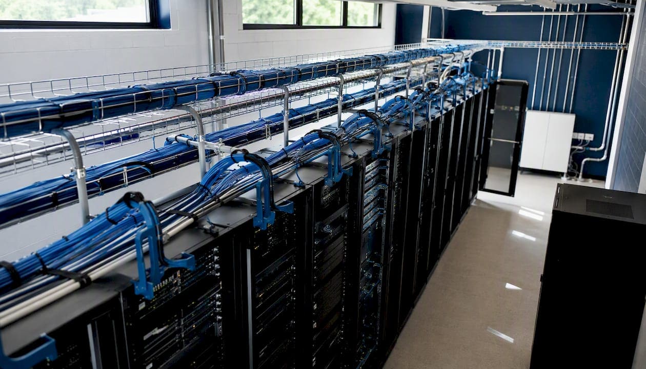
Entrance facility is the point where outside-plant cabling enters the building and connects to the internal backbone. For multi-building campuses, this is where inter-building fiber for security systems terminates.
Key components to specify by subsystem:
- Backbone: OS2 singlemode or OM4 multimode fiber, LC connectors, fiber distribution panels, splice enclosures
- Horizontal: Cat6A U/UTP or F/UTP cable (plenum-rated where required), Cat6A keystone jacks, 24-port patch panels, j-hooks at 4-foot intervals, cable trays in high-density runs
- Work area: Cat6A patch cords, surface-mount boxes, security-rated enclosures for card reader backboxes
- TR/enclosures: 19-inch or 23-inch open-frame racks, 1U or 2U patch panels, fiber enclosures, horizontal and vertical cable managers, grounding bars (TGB)
- Firestopping: UL-listed firestop putty pads, pillows, or intumescent wrap at every penetration through fire-rated assemblies
Include a star-topology diagram showing backbone fiber from MDF → TR/IDF → horizontal copper → work area security devices. Label each subsystem boundary and note the 90-meter horizontal limit.
Design and planning questions to answer before you spec anything
The most expensive mistakes in commercial security cabling happen before a single cable is pulled. These are the questions to resolve at the design stage.
Project scoping with the security team and AHJ:
- How many cameras, card readers, and intrusion sensors are planned, and where are they located? Camera counts drive PoE budget and switch port density.
- What is the PoE class requirement per device? IEEE 802.3bt Type 3 (60W) or Type 4 (90W) cameras require Cat6A to manage heat dissipation over long runs.
- Does the AHJ require dedicated conduit for security cabling, or is shared raceway with IT cabling acceptable? Some jurisdictions and insurance carriers require physical separation.
- What are the video retention requirements? Storage needs drive backbone bandwidth and NVR sizing, which in turn affect TR space and power planning.
- Is network segmentation required? Security VLANs are a software decision, but physical path diversity for critical ESS runs is a cabling decision.
For fiber backbone, pull more strands than you need today: a 12-strand OS2 run costs marginally more than a 6-strand run at installation, but adding fiber later means opening walls. A 10-year lifecycle sizing approach means planning for camera resolution upgrades, additional access points, and IP convergence of currently analog systems.
The ANSI/BICSI 007-2024 standard specifically addresses intelligent buildings where security, AV, and networking converge onto shared IP infrastructure. Planning for that convergence from the start reduces long-term costs and avoids the parallel cabling plants that create maintenance headaches. For camera-specific planning, a structured security camera cabling plan should be developed before the general cabling design is finalized.
For outside-plant backbone between buildings, utility trenching and conduit installation require coordination with site work contractors. Proper conduit depth, sweep radius, and pull-box placement at the design stage prevents costly rework during construction.
What installation best practices keep your security cabling compliant?
Compliant design on paper means nothing if the installation cuts corners. These are the site-level requirements that separate a serviceable system from one that fails inspection or fails in the field.
Pathways, conduit, and separation rules
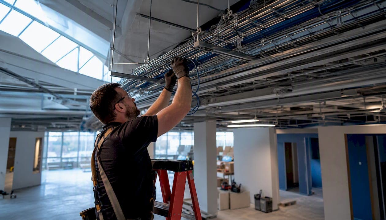
ANSI/TIA-569-D governs conduit sizing, fill ratios, and the minimum separation between low-voltage cabling and power conductors. For security cabling, maintain at least 12 inches of separation from 120V power runs in open pathways, and use metallic conduit where the pathway crosses high-voltage panels or mechanical equipment. J-hooks are acceptable for horizontal runs in open ceilings but must be spaced no more than 4 feet apart and must not support the cable’s weight at bends. Cable trays are preferred in high-density TR environments and above drop ceilings where future adds are expected.
Firestopping and plenum/riser distinctions
Every cable penetration through a fire-rated wall, floor, or ceiling assembly requires a UL-listed firestop system. ANSI/BICSI N1-2019 defines the workmanship standard for firestop installation, and the AHJ will inspect these penetrations. Require the contractor to photograph every firestop installation and submit a firestop log with the UL system designation, installer name, and date. Plenum-rated cable (CMP) is required in air-handling spaces; riser-rated (CMR) is acceptable in vertical shafts between floors. Mixing them incorrectly is a code violation and a life-safety issue.
Grounding, bonding, and cable management
ANSI/TIA-607-C requires a telecommunications main grounding busbar (TMGB) at the MDF and a telecommunications grounding busbar (TGB) in each TR, bonded to the building’s electrical ground. For security systems, proper grounding prevents ground loops that cause video noise on analog cameras and protects IP equipment from surge damage. Require bonding records as a closeout deliverable.
Abandoned cable removal is a compliance and fire-safety requirement, not a cosmetic preference. Specification language should mandate removal of all abandoned cable and require photographic evidence during closeout. Leaving dead cable in pathways violates NEC Article 800 and creates pathway congestion that complicates future work. For organized, documented TR environments, network closet best practices provide a practical framework for labeling and cable management that supports ongoing maintenance.
Installer deliverables to require at project completion:
- Bonding and grounding records (TMGB/TGB connections, conductor sizes, test results)
- Firestop log with UL system designations and photographs
- Cable route drawings showing conduit paths, j-hook runs, and tray locations
- Abandoned cable removal confirmation with photos
Both requirements cost almost nothing at installation and save significant time and money on every future add, move, or change.*
How do ESS cabling requirements differ from standard IT cabling?
Electronic Security Systems (CCTV, access control, intrusion detection) share the same physical layer as IT cabling but have distinct requirements that affect media selection, power delivery, and path design.
Dedicated vs. shared cabling infrastructure
Whether to run dedicated ESS cabling or share the IT cabling plant depends on three factors: site security policy, AHJ requirements, and insurance or facility security rules. Government facilities and high-security commercial tenants often require physically separate pathways for security cabling, with locked conduit and tamper-evident enclosures per TIA-5017. For standard commercial offices, shared Cat6A infrastructure with VLAN segmentation is common and cost-effective. The decision belongs in the design phase, not the installation phase.
PoE power delivery for cameras and access control
IEEE 802.3bt (PoE++) delivers up to 90W per port and is increasingly common for PTZ cameras, multi-sensor units, and door controllers with electric locks. Cat6A handles the heat dissipation of high-power PoE better than Cat6 over long runs, which is the primary reason industry guidance recommends Cat6A for PoE-heavy security deployments. Calculate the total PoE budget per switch before finalizing port counts: a 24-port switch with a 370W PoE budget cannot power 24 devices at 30W each simultaneously. For detailed access control cabling requirements, including power budgeting for electric strikes and mag-locks, see the access control cabling guide.
Single-pair Ethernet (SPE) and Power over Data Line (PoDL), addressed in ANSI/BICSI 007-2024, are emerging options for low-power sensors and edge devices where pulling four-pair cable is impractical. They are not yet mainstream for cameras or access control but are worth specifying in conduit design for future flexibility.
Media recommendations by device type
- IP cameras (PoE): Cat6A to 90 meters; fiber with media converter for runs beyond 90 meters or in electrically noisy environments
- Access control panels and card readers: Cat6A preferred; Cat6 acceptable for short runs under 30 meters with low PoE loads
- Intrusion detection sensors: Cat5e or Cat6 acceptable for low-bandwidth, low-power devices
- NVR/DVR backbone connections: OS2 singlemode or OM4 multimode fiber; dedicated fiber runs separate from IT backbone preferred for forensic integrity
ANSI/BICSI 005-2016 documents the ESS design best practices that underpin these recommendations, and its guidance has been incorporated into the current ANSI/BICSI 007-2024 intelligent building standard. For CCTV-specific installation details, a professional CCTV cabling infrastructure guide covers step-by-step implementation for commercial sites.
Pro Tip: For critical ESS runs (NVR feeds, access control servers, alarm panels), specify dual-path fiber routed through physically separate conduits or pathways. A single fiber cut should not take down both the primary and backup recording path.
What testing and documentation should you require from installers?
Testing is where compliance becomes provable. Require these deliverables in the contract, not as a post-installation negotiation.
Field test requirements
TIA-1152-A defines the tester accuracy class (Level IIIe for Cat6A) and the test parameters: wiremap, length, insertion loss, NEXT, PS-NEXT, ELFEXT, PS-ELFEXT, return loss, and propagation delay. A structured cabling specification that requires 100% certification and commissioning verification is the industry standard for institutional and commercial projects.
For fiber, require insertion loss testing per TIA-568.3-E using an OLTS (optical loss test set) and OTDR traces for backbone runs. Specify the acceptable loss budget in the contract (typically 0.75 dB per mated connector pair, 0.1 dB per meter of splice loss for fusion splices).
Certification testers from manufacturers such as Fluke Networks (DSX-8000) or Ideal Networks (LanTEK IV) produce native test files (.flw or .tst format) that contain the raw measurement data. Require native files, not just PDFs. PDFs can be edited; native files cannot.
Required documentation deliverables
- Test reports in both native tester format and PDF, organized by cable ID
- TIA-606-B labeling plan showing identifier scheme for cables, panels, spaces, and pathways
- As-built drawings in CAD or PDF showing actual cable routes, conduit paths, and TR layouts
- Cable schedule listing every run: cable ID, origin, destination, length, test result, and date
- Firestop log with UL system designations, locations, and photographs
- Bonding and grounding records
- Punch-list sign-off signed by the contractor and owner’s representative
For a detailed framework on what as-built documentation should contain, the structured cabling as-built documentation guide covers the full deliverable set.
Require retention of native tester files for a minimum of five years. These files are your evidence in warranty disputes and insurance claims.*
What to reject at commissioning
Reject any installation that presents: untested runs, test reports with swapped cable IDs, missing firestop records, unlabeled panels or cables, or abandoned cable left in pathways. These are not minor deficiencies. They indicate systemic workmanship problems that will cost more to fix after the contractor leaves.
Which cable type should you specify for security systems?
| Media | Best use | Max distance (structured cabling) | PoE suitability | Recommended for |
|---|---|---|---|---|
| Cat5e | Legacy or low-power sensors | 90 m (horizontal) | Limited power | Intrusion sensors, legacy analog encoders only |
| Cat6 | Standard IP devices, low PoE | 90 m (horizontal) | Moderate (up to 30W) | Low-power cameras, card readers on short runs |
| Cat6A | PoE-heavy security devices | 90 m (horizontal) | Full (up to 90W, 802.3bt) | All IP cameras, access control, WAPs |
| OM4 multimode | Intra-building backbone, NVR feeds | 550 m at 10 Gb/s | N/A (fiber) | Building backbone, TR-to-TR, NVR connections |
| OS2 singlemode | Campus backbone, long runs | 10+ km | N/A (fiber) | Inter-building, high-security backbone, future high speeds |
Cat6A is the practical standard for any PoE security device. The thermal performance advantage over Cat6 at high PoE loads is real, and the cost difference at installation is small relative to the cost of a recabling project five years later. ANSI/TIA-568.1-E added guidance for WAP cabling and single-pair Ethernet in its most recent revision, reflecting the direction device manufacturers are moving. For backbone design decisions, the fiber optic backbone design guide covers OS2 vs. OM4 selection in commercial office environments.
OS2 singlemode is the right choice for any backbone where future bandwidth growth is uncertain, which describes most commercial buildings. The incremental cost of singlemode fiber over multimode is offset within one technology refresh cycle.
What compliance gaps cause failed inspections and expensive rework?
Most cabling failures at inspection or commissioning trace back to a short list of avoidable mistakes.
AHJ coordination checkpoints to verify before installation begins:
- Conduit fill ratios per NEC Article 358/362 and local amendments
- Separation requirements between low-voltage and power conductors (NEC Article 800)
- Firestop system approval: some AHJs require pre-approval of the UL system designation before installation
- Raceway routing through fire-rated assemblies: confirm penetration locations with the structural drawings
Common mistakes that cause rework:
- Cable spaghetti in TRs: unlabeled bundles that cannot be traced without pulling every cable
- Missing or incorrect labeling: panels labeled in marker that fades, or labels that don’t match the as-built drawings
- Untested runs: contractor submits a partial test report covering only the runs they tested
- Plenum/riser mixing: CMR cable installed in an air-handling plenum space, which fails fire inspection
- Inadequate spare capacity: conduit filled to 100% at installation, leaving no room for adds
- Abandoned cable: previous-generation cabling left in pathways, violating NEC Article 800 and creating fire load
- No as-built drawings: the contractor delivers a test report but no drawings, leaving the owner with no record of where cables run
Red flags in contractor bids that indicate compliance risk:
- No mention of TIA-1152-A testing or certification in the scope of work
- No as-built drawings or labeling plan in the deliverables list
- Warranty language that excludes labor for remediation of failed tests
- No BICSI credentials or equivalent documented experience listed for field technicians
- Lump-sum pricing with no line item for testing, documentation, or firestopping
For NYC-specific AHJ coordination and building constraints, understanding how building cabling infrastructure works in NYC provides local context that generic standards documents do not cover.
Contractor-ready checklist and RFP spec language
Use these snippets directly in your RFP or scope of work.
Minimum spec language for RFP inclusion
- Standards compliance: All work shall conform to ANSI/TIA-568.1-E, ANSI/TIA-568.0-D, ANSI/TIA-568.2-D, ANSI/TIA-568.3-E, ANSI/TIA-569-D, ANSI/TIA-606-B, ANSI/TIA-607-C, ANSI/TIA-862-B, ANSI/TIA-1152-A, ANSI/BICSI 005-2016, and ANSI/BICSI 007-2024, current editions.
- Media minimums: Horizontal copper: Cat6A minimum, plenum-rated (CMP) where required. Backbone fiber: OM4 multimode or OS2 singlemode as specified per run.
- Testing: 100% of installed copper runs shall be certified using a TIA-1152-A-compatible tester (Level IIIe accuracy class minimum). All fiber runs shall be tested with an OLTS and OTDR. Native tester files and PDF reports shall be delivered at closeout.
- Labeling: All cables, panel ports, spaces, and pathways shall be labeled per ANSI/TIA-606-B. Labels shall be machine-printed, not handwritten.
- As-built drawings: Contractor shall deliver as-built drawings in CAD or PDF format within 10 business days of commissioning sign-off.
- Installer qualifications: Field technicians shall hold BICSI Installer 2 certification or equivalent documented experience. The project lead shall hold RCDD or equivalent.
- Firestopping: All cable penetrations through fire-rated assemblies shall be sealed with UL-listed firestop systems. A firestop log with photographs shall be submitted at closeout.
- Abandoned cable removal: All abandoned cable shall be removed from pathways and TRs. Photographic evidence of removal shall be submitted at closeout.
Project punchlist by phase
Planning phase:
- Confirm AHJ requirements for separation, conduit fill, and firestop approval
- Finalize camera counts, PoE class requirements, and device locations
- Determine dedicated vs. shared ESS cabling policy
- Size conduit with 20–30% spare capacity
- Confirm TR dimensions and power/cooling capacity per TIA-569-D
Installation phase:
6. Verify conduit installation before cable pull (fill ratio, sweep radius, pull-box spacing)
7. Confirm plenum vs. riser cable selection per space type
8. Photograph all firestop installations before concealment
9. Label cables at both ends and at 1-meter intervals in TRs during installation
10. Maintain separation from power conductors throughout
Testing and commissioning phase:
11. Certify 100% of copper runs with TIA-1152-A-compatible tester
12. Test all fiber runs with OLTS and OTDR
13. Verify TIA-606-B labeling matches test report cable IDs
14. Confirm all panel ports are patched and labeled correctly
15. Conduct walk-through with owner’s representative before sign-off
Closeout phase:
16. Deliver native tester files and PDF test reports
17. Deliver as-built drawings and cable schedule
18. Deliver firestop log with photographs
19. Deliver bonding and grounding records
20. Confirm abandoned cable removal with photographic evidence
Why standards compliance is the difference between a system that works and one that fails
The buildings where cabling problems show up most visibly are not the ones that ignored standards entirely. They are the ones that followed standards selectively, treating labeling as optional or testing as a formality. A facilities manager inheriting a building with unlabeled panels and no as-built drawings faces a real problem the first time a camera goes offline at 2 AM and no one can trace which run feeds it.
Standards compliance is not about paperwork. It is about building a system that someone other than the original installer can service, troubleshoot, and extend. TIA-606-B labeling and as-built drawings are what make that possible. TIA-1152-A testing is what proves the cabling will perform under load, not just at the moment of installation. Grounding per TIA-607-C is what prevents a surge event from taking out a row of IP cameras.
The pattern that causes the most expensive rework is not a single bad decision. It is a series of small compromises: Cat6 instead of Cat6A to save a few dollars per run, skipped test reports to meet a deadline, labels applied in marker instead of machine-printed. Each one seems minor. Together, they produce a system that fails within three years and costs more to remediate than the original installation.
For secure facilities, the stakes are higher. Physical path diversity, tamper-evident enclosures, and locked TRs are not optional features. They are the difference between a security system that functions as designed during an incident and one that can be defeated by cutting a single cable run. BICSI ESS guidance exists precisely because general IT cabling standards do not address these requirements in enough detail for high-security environments.
Cables and Chips delivers compliant security cabling for commercial buildings in NYC
Cables and Chips designs, installs, and certifies structured cabling for commercial offices, secure facilities, and enterprise environments throughout New York City. With more than 40 years of experience, the team handles Cat6A and Cat6 horizontal runs, OS2 and OM4 fiber backbone installation, CCTV and access control cabling, TIA-606-B labeling, and full as-built documentation, all delivered to TIA and BICSI standards.

For facilities managers and IT directors who need a contractor that can produce a compliant, documented, serviceable installation, Cables and Chips provides the CCTV and access control installation and structured cabling services to meet those requirements. Contact Cables and Chips to schedule a site survey or request an RFP-ready spec template for your next security cabling project.
Sources
- ANSI/BICSI 005 Standards for Electronic Safety and Security
- Structured Cabling/Security System Specification | Information Systems & Technology | University of Waterloo
Standards documents are available for purchase directly from TIA and BICSI. For projects where purchasing the full standard set is not practical, BICSI’s RCDD-certified contractors are required to work to current editions, so specifying BICSI-certified installers effectively imports the standards requirements into the project.
FAQ
What is the standard for commercial building telecommunications wiring?
ANSI/TIA-568.1-E is the primary standard for commercial building telecommunications cabling, covering backbone, horizontal, and work area subsystems. It is used alongside ANSI/TIA-569-D (pathways), ANSI/TIA-606-B (labeling), and ANSI/TIA-607-C (grounding) for a complete cabling system specification.
What does ANSI/TIA-568 cover?
The TIA-568 series covers the design, installation, and performance requirements for premises telecommunications cabling. TIA-568.1-E addresses commercial buildings specifically; TIA-568.2-D covers balanced twisted-pair (Cat5e through Cat8); TIA-568.3-E covers optical fiber specifications.
What is the ANSI/TIA-568.3-E standard?
ANSI/TIA-568.3-E specifies optical fiber cabling performance requirements for premises applications, including insertion loss, return loss, and connector performance for multimode (OM1 through OM5) and singlemode (OS1/OS2) fiber used in structured cabling systems.
What cabling standards apply specifically to security systems?
ANSI/BICSI 005-2016 and ANSI/BICSI 007-2024 provide ESS-specific design guidance for CCTV, access control, and intrusion systems. ANSI/TIA-862-B covers building automation and integrated systems cabling. TIA-5017 addresses physical network security at the cabling layer for high-security environments.
How do you verify that a security cabling installation is compliant?
Verify TIA-606-B labeling matches the as-built drawings and test report cable IDs, and confirm firestop logs and bonding records are complete before signing off.