
How to Run Low Voltage Cabling in Ceilings: 2026 Guide
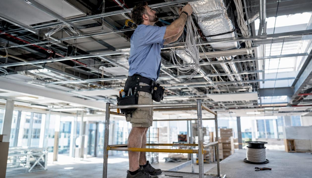
Running low voltage cabling through ceiling spaces correctly means selecting the right cable rating for the environment, supporting cables independently from the building structure at appropriate intervals, and maintaining physical separation from power conductors. The National Electrical Code (NEC) 2026, specifically NEC 300.13(B), consolidates requirements for wiring above suspended ceilings: cables must never rest on ceiling grids or tiles, and any independent support wires must be secured at both ends and distinguishable from ceiling grid wires by color, tagging, or other clear means.
The core rules for compliant ceiling cable installation:
- Use CMP-rated cable in plenum air-handling spaces, CMR in vertical risers, and CM in general horizontal runs. Substituting downward is a code violation.
- Support cables at appropriate intervals using listed J-hooks, bridle rings, cable trays, or basket trays attached to the building structure.
- Never lay cables on ceiling tiles or hang them from conduit, sprinkler pipes, or HVAC components per NEC 300.11 and Article 800.
- Maintain 6–12 inches of parallel separation from unshielded 120/240V power conductors; cross power runs at 90 degrees.
- Remove accessible abandoned cable to reduce fire load and pass inspection.
How to run low voltage cabling through finished and dropped ceilings
Finished ceilings and dropped ceiling systems each present different routing challenges, and the right technique depends on what you are working with.
For finished drywall ceilings, the standard approach is drilling through joists or framing and feeding cable through the cavity. Use a flexible drill bit and a fish tape or pull string to navigate the run. At every penetration through a fire-rated assembly, install a listed firestop sleeve or apply listed firestop caulk around the cable. Skipping this step fails inspection and compromises the fire rating of the assembly.
Dropped ceiling systems are more accessible but carry their own code requirements. You can route cables above the tiles through the plenum cavity, but the tiles themselves are not a support surface. Use sleeves or bushings wherever cable passes through a tile or grid member to protect the jacket and preserve any fire rating at that penetration point.
- Drill holes through framing for finished ceilings; use fish tape or pull string to feed cable.
- Install firestop sleeves at every penetration through rated assemblies.
- Route above dropped ceiling tiles, never on top of them.
- Use bushings or grommets at tile penetrations to protect cable jackets.
- In tight spaces, use a right-angle drill attachment or flexible bit extension to reach confined framing cavities.
Pro Tip: In a commercial office buildout, photograph every penetration before closing the ceiling. That documentation speeds up future inspections and troubleshooting considerably.
How to support and secure cables in ceiling spaces per NEC
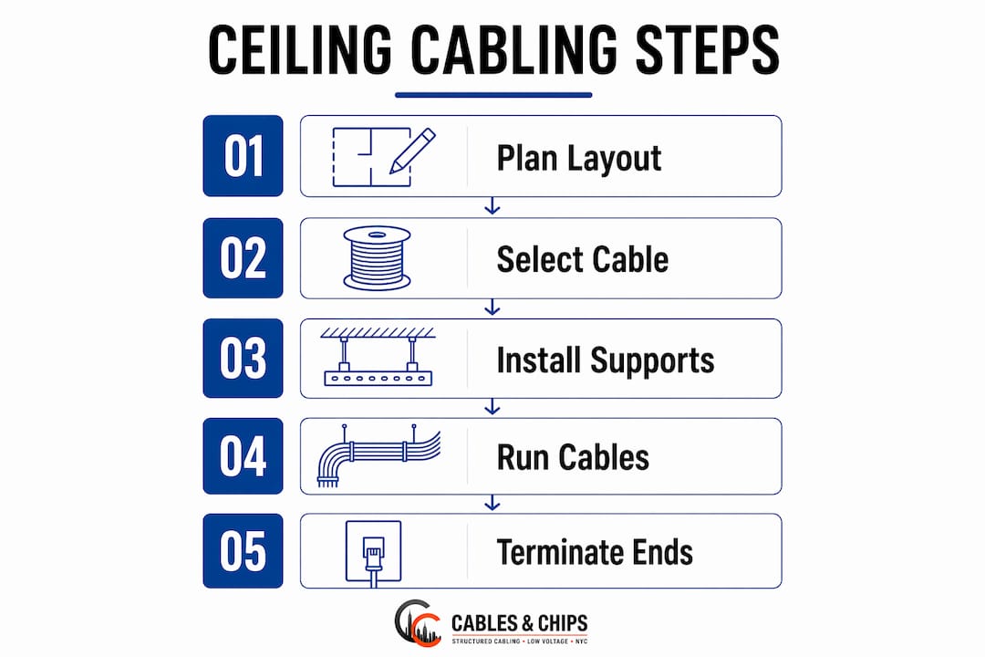
Proper support is where most ceiling cable installations either pass or fail inspection. BICSI and TIA-569 specify that horizontal cable supports should be placed at suitable intervals, with closer spacing at direction changes and near vertical drops for support.
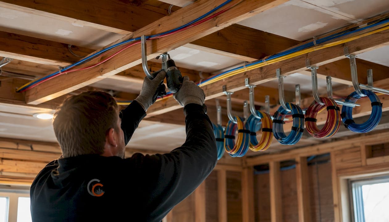
J-hooks must attach to the building structure, not the ceiling grid. Common methods include threaded rod dropped from the deck, beam clamps on bar joists or I-beams, and rated wood or concrete anchors for block or drywall construction. The ceiling grid is rated to carry tiles, not cable bundles. Adding cable load to the grid is a code violation and risks collapse.
NEC 300.11 and Article 800 explicitly prohibit supporting communications cables from sprinkler pipes, HVAC ducts, or electrical conduit. These are not listed supports and create both mechanical and fire hazards.
- Space J-hooks at appropriate intervals for straight horizontal runs; use closer spacing at transitions and bends.
- Support within 24 inches of every vertical drop point.
- Attach all supports to the building structure, never to the ceiling grid or its wires.
- Use #12 AWG minimum wire gauge for independent support wires in fire-rated assemblies.
- Independent support wires must be secured at both ends and distinguishable from ceiling grid wires by color or tagging per NEC 300.13(B).
Code note: Per NEC 300.13(B), independent support wires above suspended ceilings must meet four conditions: installed in addition to ceiling grid wires, distinguishable from them, secured at both ends, and providing secure support. All four must be satisfied, not just one or two.
What to plan before you pull a single foot of cable
Thorough pre-installation planning is the single largest factor in a successful cabling project. That means walking the ceiling space before ordering materials, not after.
Start by confirming the plenum status of every ceiling cavity your cable will pass through. Get written confirmation from the mechanical engineer or architect. Inspectors frequently require CMP-rated cable above drop ceilings by default, and without documentation proving the space is not used for air return, you may be forced into a costly rework. When in doubt, specify CMP throughout.
Map your conduit routes, firestop locations, and cable paths on the building drawings before pulling anything. Identify where cable will cross power runs and plan perpendicular crossings. Confirm that your cable ratings match every segment of the route, because a single two-foot section through a plenum space requires the entire run to be CMP-rated. You cannot splice jacket types mid-run.
- Survey ceiling type and confirm plenum status in writing before ordering cable.
- Map all conduit routes, firestop requirements, and power crossing points on drawings.
- Confirm CMP, CMR, or CM rating for each segment of the cable path.
- Plan physical separation from power wiring; avoid shared raceways or junction boxes.
- Pre-mark support points every 4–5 feet along the route with tape before mounting hardware.
- Document the planned path with photos before installation begins.
For security camera and access control runs, mapping conduit and firestop needs before ceiling work begins is especially critical. Cables and Chips covers this in detail for commercial security cabling projects.
Expert insights from Cables and Chips on NEC 2026 compliance
Cables and Chips has completed low voltage ceiling cable installations across commercial offices, secure facilities, and enterprise environments throughout New York City for more than 40 years. The pattern on failed inspections is consistent: improper support and wrong cable ratings account for the majority of red-tagged jobs.
The 2026 NEC consolidation of ceiling support requirements into 300.13(B) eliminates the previous confusion between fire-rated and non-fire-rated assembly rules. The practical effect is straightforward: no cable or raceway touches the ceiling grid, independent support wires go to the building structure at both ends, and those wires are visually distinct from the grid. Color-coded support wire is the simplest way to satisfy that last requirement.
On J-hook spacing, the practical standard is every 4–5 feet for horizontal runs. Tighten to 3 feet at direction changes and within 24 inches of vertical drops to maintain bend radius and cable geometry, especially on Cat6A runs where alien crosstalk is already a concern.
Pro Tip: Install all J-hooks and support hardware before pulling cable. Pre-marking support points with blue tape on the deck, then photographing the marked path, gives you job documentation and speeds the pull significantly.
Why laying cables on ceiling tiles creates serious problems
Resting cable on ceiling tiles is one of the most common installation errors, and it creates problems that compound over time. NEC 800.24 requires communications cabling to be installed in a workmanlike manner with adequate support. Ceiling tiles are not rated as cable supports, and the code is explicit on this point.
The mechanical risk is real. When a tile is removed for maintenance, any cable resting on it drops, bends sharply, or gets pinched. Repeated tile removal crushes the cable jacket and deforms the twisted pairs inside, degrading signal performance. On a Cat6 or Cat6A run, that kind of physical damage can cause a link to fail certification even when the cable itself looks intact from the outside.
Beyond signal loss, there is a code violation and inspection risk. Fire marshals and AHJ inspectors check for cable on tiles as a standard item. A flagged installation means rework on the entire run, not just the section where the problem was spotted.
Fire safety requirements for ceiling cable installations
Fire safety in ceiling cable work comes down to two things: cable jacket rating and firestopping at penetrations. Get either one wrong and the installation creates a hazard the building’s fire suppression system cannot fully address.
Plenum-rated CMP cable uses a jacket material that produces significantly less smoke and fewer toxic gases in a fire than standard PVC. In a return-air plenum ceiling, all building air passes through that space back to the HVAC handler. Standard PVC burning in that space sends dense smoke and chlorine-containing gases throughout the building via the HVAC system. CMP cable reduces that hazard at the source.
At every penetration through a fire-rated floor-ceiling or wall assembly, install listed firestop materials sized for the cable type and penetration diameter. Firestop caulk, intumescent sleeves, and listed putty pads are all acceptable depending on the assembly type. Using metal conduit through a penetration does not eliminate the firestop requirement; the annular space around the conduit still needs to be sealed with listed material. For projects where utility ducting and conduit routing are part of the broader construction scope, coordinate firestop requirements with the general contractor before ceiling work begins.
How to avoid electrical interference and protect signal integrity
Physical separation from power conductors is the primary defense against electromagnetic interference on low voltage cable runs. NEC 800.133 requires communications cable to be kept separate from electrical light and power conductors. The practical standard is 6–12 inches of parallel separation from unshielded line-voltage runs; some local jurisdictions and project specifications require 24 inches.
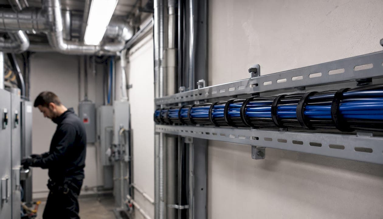
Where cable paths must cross power runs, cross at 90 degrees. A perpendicular crossing minimizes the coupling length between the conductors and keeps induced noise below the threshold that affects data transmission. Never run low voltage cable parallel to power conductors in the same raceway or through the same drilled hole without a listed separator.
Cable handling during the pull also affects signal integrity. Pull cables sequentially rather than threading entire bundles through J-hooks at once, which causes twisting and deforms pair geometry. Keep bend radius at 4 times the cable diameter at every transition. Cable ties pulled too tight crush the jacket and can fail certification on a link that otherwise looks clean.
How to work safely in confined ceiling spaces
Ceiling spaces in commercial buildings are often congested with HVAC ductwork, sprinkler piping, conduit, and existing cable runs. Working efficiently in those conditions requires preparation before you go up.
Use a headlamp rated for the work environment and carry a flexible inspection camera to scout the path before committing to a route. In spaces with limited clearance, a right-angle drill and flexible bit extension let you drill through framing without repositioning a ladder repeatedly. For high ceilings or open bays where ladder access is limited, an extension pole rated for the reach lets a single technician place J-hooks and guide cable from the floor.
Never stand on ceiling tiles or the grid system to reach a work area. The grid is not rated for body weight. Use a properly rated ladder or scaffold positioned to reach the work point directly. Wear appropriate PPE including eye protection when drilling overhead, and confirm the space above the ceiling is not energized before reaching into it.
How to terminate and connect low voltage cables after ceiling runs
Termination quality determines whether a cable run that was installed correctly actually performs correctly. A clean pull through the ceiling means nothing if the termination at each end introduces return loss or crosstalk.
At patch panels and keystone jacks, maintain the twist in each pair as close to the termination point as possible. Untwisting more than half an inch of pair at a Cat6 or Cat6A termination degrades high-frequency performance. Follow the T568B wiring standard consistently across the installation unless the project specification requires T568A; mixing standards on the same link causes a miswire that fails continuity testing.
Label every cable at both ends before terminating. Use a consistent labeling scheme tied to the as-built documentation. After termination, test every link with a cable certifier, not just a continuity tester. Certification confirms that the link meets TIA-568 performance standards end to end, including insertion loss, return loss, and crosstalk parameters. For structured cabling documentation practices, Cables and Chips provides detailed guidance on as-built documentation that supports long-term serviceability.
Cables and Chips brings 40 years of ceiling cabling expertise to your project

Cables and Chips is the low voltage contractor for commercial offices, secure facilities, and enterprise environments across New York City that need ceiling cable installations done right the first time. With more than 40 years of field experience and a team that works to NEC 2026 standards on every project, Cables and Chips handles the full scope: cable selection and rating verification, J-hook layout and support installation, firestopping at penetrations, pull and termination, certification testing, and as-built documentation.
The difference between a job that passes inspection and one that gets red-tagged usually comes down to planning and support hardware. Cables and Chips starts every project with a site survey that confirms plenum status, maps cable paths against power runs, and identifies firestop requirements before a single hook goes up. For IT managers and building teams who need structured CAT6 cabling installed to spec in occupied commercial space, that level of preparation is what keeps projects on schedule.
Contact Cables and Chips to schedule a site survey for your ceiling cabling project.
Key Takeaways
Running low voltage cabling through ceiling spaces correctly requires the right cable rating, independent structural support every 4–5 feet, and firestopping at every rated penetration.
| Point | Details |
|---|---|
| Cable rating by location | Use CMP in plenum air-handling spaces, CMR in vertical risers, and CM in general horizontal runs. |
| Support spacing | Space J-hooks every 4–5 feet for horizontal runs, tighten to 3 feet at bends and within 24 inches of vertical drops. |
| NEC 300.13(B) compliance | Independent support wires must be secured at both ends, distinguishable from grid wires, and attached to building structure. |
| Separation from power | Maintain 6–12 inches of parallel separation from unshielded line-voltage conductors; cross at 90 degrees. |
| Cables and Chips | Provides NEC 2026-compliant ceiling cabling installation for commercial and enterprise environments across New York City. |
FAQ
How do you run cable along a ceiling without violating code?
Attach listed J-hooks or bridle rings to the building structure at intervals appropriate for cable support and route cable through them. Never rest cable on ceiling tiles or hang it from conduit, sprinkler pipes, or HVAC components, as NEC 800.24 prohibits those methods.
What cable rating do you need above a drop ceiling?
If the ceiling space is used for HVAC return air, CMP-rated plenum cable is required. If the space is not used for air return and you have written confirmation from the mechanical engineer, CMR is the minimum; when in doubt, default to CMP to avoid failed inspections.
Can you run MC cable above a drop ceiling?
Metal-clad (MC) cable is a power wiring method and must be kept physically separate from low voltage communications cables. Low voltage cables above a drop ceiling must be independently supported from the building structure and cannot share raceways or supports with MC cable runs.
Can you run low voltage wire without conduit?
Yes. Low voltage communications cable does not require conduit in most ceiling spaces, provided it is properly supported on listed J-hooks or cable tray every 4–5 feet and uses the correct jacket rating for the space. Conduit is required at penetrations through fire-rated assemblies and where local AHJ rules mandate it.
How far apart should J-hooks be spaced for low voltage cable?
BICSI and TIA-569 specify a maximum of 5 feet on center for horizontal runs, with the practical standard at 4–5 feet. Tighten to 3 feet at direction changes and within 24 inches of vertical drops.