
RS-485 Access Control Wiring: A Technician’s Field Guide

The most reliable RS-485 access control wiring uses a linear daisy-chain bus, 120 Ω termination resistors at both physical ends, shielded twisted-pair cable in the 22 to 24 AWG range, and a single signal ground point. Drops to each reader stay short and insulated, and every device address gets assigned before commissioning begins.
Before running a single foot of cable, confirm these five things on site:
- Topology: linear bus planned end to end, no star or T-tap branches
- Cable: shielded twisted pair, 22 to 24 AWG, 120 Ω characteristic impedance
- Termination: resistors sized for both physical ends of the trunk, not the middle
- Shield and ground: one earth bond point identified, typically at the controller cabinet
- Address plan: every reader assigned a unique address on paper before install day
Do not treat leftover CAT5 or CAT6 as a permanent substitute for RS-485 trunk cable without the controller manufacturer’s written approval. It often works on day one and fails intermittently six months later.
Key Takeaways
A reliable RS-485 access control bus depends on linear topology, 120 Ω termination at both physical ends, shielded twisted-pair cable, and a single-point shield ground.
| Point | Details |
|---|---|
| Use a linear bus | Wire readers in a daisy-chain sequence; avoid star wiring or T-taps without an approved hub. |
| Match cable to impedance | Choose 22 to 24 AWG shielded twisted pair rated for 120 Ω, not repurposed CAT5/6, for trunk runs. |
| Terminate both ends only | Enable 120 Ω termination at the two physical ends of the trunk, never mid-bus. |
| Ground the shield once | Bond the shield to earth at the controller cabinet only, leaving the far end insulated. |
| Get professional installation | Cables and Chips designs, installs, and tests RS-485 access control cabling for commercial buildings in New York City. |
What Is RS-485 Wiring and Why Topology Comes First
RS-485 is a differential serial communication standard defined under EIA/TIA specifications, built to move data reliably over long runs in electrically noisy commercial environments. For access control specifically, the physical layout you choose determines whether the bus behaves for ten years or generates callbacks in month three.
A linear daisy-chain bus means the trunk cable runs from the controller to reader one, then reader one to reader two, and so on, ending at the last device. Star wiring, where multiple readers branch off a single point, and T-taps, where a drop splits mid-cable, both violate standard RS-485 bus guidance unless a proper RS-485 hub or multiplexer manages the split. Unmanaged branches create impedance mismatches that reflect signal energy back down the line.
Route the trunk along the building’s low-voltage backbone, not alongside electrical conduit. Keep drops to readers as short as the site allows.
- Readers and card readers belong on the RS-485 bus itself, in sequence
- Door strikes, REX sensors, and door contacts typically wire directly to the local controller, not the RS-485 trunk
- Avoid running the trunk parallel to fluorescent ballasts, VFDs, or high-current conduit for more than a few feet
Choosing the Right RS-485 Cable Type and Pair Assignments
Specify stranded, twisted-pair, shielded cable at 22 to 24 AWG for trunk runs, matched to a 120 Ω characteristic impedance. That impedance figure is not a suggestion. It is the number termination resistors are calculated against, and mismatched cable is one of the most common reasons a bus that tests fine on the bench misbehaves once installed.
Plenty of installers ask whether leftover CAT5 or CAT6 will work. For a drop under 10 feet, it usually holds up fine. For a 500-foot trunk connecting a dozen readers, LAN cable’s impedance and capacitance characteristics differ enough from true RS-485 cable that long-term reliability suffers, even when initial testing looks clean.
- Reserve one twisted pair for A/B data signals
- Use a second conductor or pair for signal ground (SG) when the controller specifies one
- Keep power conductors in a separate jacket section or run separate power cable entirely when combining data and power in one sheath
Pro Tip: Order a spare labeled pair in every trunk pull. Adding a reader or migrating to OSDP later becomes a splice-free job instead of an unplanned demo.
Termination and Biasing: Getting the Ends Right
Every RS-485 trunk needs 120 Ω termination resistors at both physical ends, sized to match the cable’s characteristic impedance and nowhere else along the run. Terminating a device in the middle of the bus, a mistake more common than it should be, creates the same reflection problems as skipping termination entirely.
Most access control controllers include on-board termination, activated through a jumper or DIP switch rather than a separate resistor pack. If the controller sits in the middle of a bus rather than at an end, that on-board termination link should stay off, and an external resistor goes at the true physical end instead.
- Enable termination only at the two devices physically farthest apart on the trunk
- Check controller documentation for jumper or switch labeling before assuming defaults are correct
- Add fail-safe bias resistors when the bus needs to hold a defined idle state, particularly on longer or noisier runs
Pro Tip: Termination should be planned from the start of the job, not added later. Retrofitting resistors after a system is already misbehaving in the field takes far longer than setting them correctly during initial pull.
Grounding and Shielding to Prevent Ghost Faults
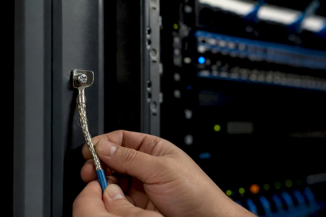
Connect the cable shield to earth ground at one end only, typically inside the controller cabinet, and leave the far end insulated and floating. Grounding both ends creates a path for stray current to flow through the shield itself, which is exactly how ground loops produce intermittent “ghost” faults that read locks, offline readers, or garbled card data with no obvious cause.
The signal ground conductor, when the controller specifies one, is not interchangeable with the shield. SG carries a reference voltage between devices; the shield exists purely to reject electrical noise.
- Bond the shield to the cabinet earth point, not to a random junction box ground screw
- If a metal enclosure houses the controller, confirm it has its own proper earth bond
- A reader that drops offline only during storms or when nearby equipment cycles on is a classic ground loop symptom
Pro Tip: If two “grounded” points in the building read differently on a multimeter relative to true earth, you’ve found your loop. Fix the bond point, not the reader.
Powering Readers Without Wrecking the Signal Path
Keep down-lead drops to readers short, ideally under 10 feet, using shielded 24 AWG cable that matches the trunk’s characteristics rather than whatever spare cable happens to be on the truck. Longer drops act like small antennas and start picking up noise the trunk itself was designed to reject.
Most controllers can source power to nearby readers directly, but longer runs or higher-draw devices often need a local power supply instead. Protect lock and REX circuits with diodes or dedicated supply wiring so switching transients don’t ride back into the data pair.
- Avoid running reader power in the same conduit as long parallel mains runs
- Where a data cable must cross a power line, cross it at 90 degrees, never alongside it
Addressing, Baud Rate, and How Many Devices Fit on One Trunk
Every reader needs a unique address on the bus, set before wiring begins, not discovered during commissioning when two devices are fighting over address 04. Build an address map on paper first, including spares for future expansion.
Baud rate and distance trade against each other directly. Push the baud rate up and the maximum reliable trunk length comes down, since higher speeds are more sensitive to cable capacitance and reflection over distance.
- Manufacturer limits commonly run 2,000 to 4,000 feet depending on baud rate and cable quality
- One access control vendor documents 1,000 meters (3,000 feet) as the recommended maximum using standard UTP
- Node counts per trunk typically range from several up to a few dozen devices, set by the controller manufacturer, not the RS-485 standard itself
A Step-by-Step Troubleshooting Sequence for a Failing Bus
When a reader bus starts throwing errors, work through checks in order of effort rather than jumping straight to a protocol analyzer.
- Inspect physical connections: polarity at A/B terminals, continuity end to end, and connector seating at every reader
- Check for shorts or damage at junction boxes and reader back boxes
- Confirm termination is enabled only at the two physical ends, never in the middle
- Verify the shield is grounded at one point only and the SG conductor is intact
- Measure drop lengths against vendor limits and check for parallel runs near power cable
- Confirm every reader has a unique address and the controller and readers agree on baud rate
A quick meter check across A/B with power removed should read close to 60 Ω, the result of two 120 Ω resistors in parallel at the trunk’s ends. A reading near 120 Ω often means only one terminator is active; a very low reading suggests a short.
- One successful card read does not confirm a healthy bus. Retransmissions can mask intermittent errors until traffic increases
- A protocol analyzer or oscilloscope helps when basic checks come back clean but errors persist
Field-Tested Tips That Cut Callbacks
Reusing CAT5 or CAT6 for a long RS-485 trunk is one of the most common sources of intermittent problems installers see, particularly past 200 or 300 feet with multiple readers on the line. It’s a reasonable choice for a short drop under 10 feet where the mismatch barely registers, but treating it as a permanent trunk solution invites service calls later.
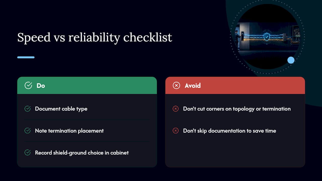
Label every trunk segment and document the address map, termination state, and shield ground point inside the cabinet before closing it up. The next technician who opens that panel, possibly years later, shouldn’t have to guess.
- Leave slack in junction boxes, not tight coils that stress connectors
- Pull a spare labeled pair for future OSDP migration or added sensors
- Test with a loopback plug and a basic meter before assuming a fault is complex
Pro Tip: A cable certifier gives you a documented pass/fail on impedance and continuity before the drywall closes, which is far cheaper than chasing a ghost fault after occupancy. Reviewing access control cabling requirements during the planning phase catches most of these issues before they’re buried in a wall.
Speed vs. reliability: what actually matters on a typical commercial install
Every job has pressure to finish faster. Cutting corners on topology or termination to save an afternoon almost always costs more later in service calls. Document cable type, termination placement, and shield ground decisions in the cabinet. Future technicians, including you on a return visit, will need that record.
Get Professional Help Wiring Your Access Control RS-485 Bus
Getting RS-485 wiring right on paper is one thing. Getting it right across a multi-floor commercial building with dozens of doors, existing tenant infrastructure, and a compressed construction schedule is another. Cables and Chips designs and installs structured access control cabling for commercial offices and secure facilities throughout New York City, handling trunk routing, termination, shielding, and documentation as one coordinated scope.

Beyond initial installation, Cables and Chips provides cable testing and certification to confirm impedance and continuity before walls close, plus on-site troubleshooting when an existing bus starts throwing intermittent errors. For projects that combine access control with broader network infrastructure, our team also handles the surrounding structured cabling scope. If your next project needs a properly wired RS-485 bus or an as-built record of one already installed, request a site survey and we’ll walk the space with you.
Sources
Keep these on hand before commissioning any RS-485 access control job:
- RS-485 Basics: When Termination Is Necessary, and How to Do It Properly – TI
- RS-485 – Wikipedia
- RS-485 Communication Wiring – Avigilon Support
- RS485 termination resistor and cable impedance guide – Industrial Monitor Direct
FAQ
Is RS-485 two-wire or three-wire?
Most RS-485 access control installations use two wires (A and B) for data, plus a separate signal ground conductor when the controller specifies one, making it effectively a two-wire or three-conductor system depending on the manufacturer.
How many wires does RS-485 need?
At minimum, RS-485 needs two conductors for the A/B differential pair; many access control installations add a third conductor for signal ground and separate conductors for power when combining data and power in one cable.
What is the difference between two-wire and four-wire RS-485?
Two-wire RS-485 uses a single twisted pair for half-duplex communication in both directions, which is standard for access control readers, while four-wire RS-485 uses separate pairs for transmit and receive, enabling full-duplex communication but requiring more conductors.
Does RS-485 need a terminating resistor?
Yes, in nearly all practical installations. A 120 Ω resistor belongs at each physical end of the trunk to match the cable’s characteristic impedance and prevent signal reflections, and skipping termination is only advisable for very short, low-speed segments.
Can I use CAT6 cable for RS-485 access control wiring?
CAT6 can work for short drops under 10 feet, but it lacks the impedance characteristics of true 120 Ω RS-485 cable, so manufacturers generally advise against using it for long trunk runs connecting multiple readers.