
How to Remediate Failing Cabling Infrastructure

Start by isolating the affected link, run a permanent-link certification test to ANSI/TIA-568 limits, then apply the reterminate-vs-replace decision rule before touching anything else. That sequence prevents wasted effort and gives you defensible evidence before a vendor sets foot on your floor. To remediate failing cabling infrastructure correctly, you need three things working together: a structured diagnostic process, the right test equipment, and a contractor who delivers certified test reports as a contractual deliverable, not an afterthought.
Immediate actions to take right now:
- Swap the patch cord at both the device and switch ends with a known-good cord. Most intermittent drops trace back to a damaged patch cord, not the permanent run.
- Move the affected device to a known-good switch port to rule out a failed switch PHY.
- Enable switch port logging (link-state and error counters) so you have a timestamped record of flaps and CRC errors before any work begins.
- Schedule a permanent-link certification test using a Fluke Networks or NetAlly-class certifier configured to the correct category (Cat6, Cat6A, or fiber).
- If the run fails or shows marginal results, apply the reterminate-vs-replace decision rules covered in Section 5.
What to require from any remediation vendor:
- BICSI-certified or BICSI-trained technicians, per the BICSI Installation Handbook (v8)
- Certified test reports from a Fluke Networks or NetAlly-class certifier, saved by cable ID
- A port map and as-built documentation (CSV or Visio)
- Before-and-after photos of every remediated area
- A written workmanship warranty covering the remediated channels
Cables and Chips provides all five deliverables on every commercial remediation project in New York City.
Pro Tip: Before calling a vendor, pull your switch’s error counters for the affected port. High CRC counts with occasional flaps almost always point to a physical-layer problem, not a software or device issue. That data also helps a vendor scope the work accurately before the site visit.
What are the most common signs of failing cabling?
Failing cabling rarely announces itself cleanly. The symptoms tend to look like software problems, device failures, or switch misconfigurations, which is exactly why physical-layer diagnostics get skipped too long.
Physical symptoms to watch for:
- Intermittent link drops and port flaps, especially on specific ports or in specific areas
- Auto-negotiation downshifts from 1G to 100 Mbps on ports that should run at full gigabit
- PoE-powered devices (IP cameras, wireless access points, VoIP phones) rebooting without explanation
- High CRC error counts or frame errors on switch port statistics
- Localized latency spikes that correlate with time of day or temperature changes
Root causes by category:
Physical damage is the most straightforward: crushed or kinked runs from furniture or cable trays, tight bend radii at corners or through conduit, water intrusion, rodent damage, and thermal cycling in unconditioned spaces. EMI from parallel power runs is a frequent offender in older buildings where data and electrical were never properly separated.
Installation quality problems are subtler. Mixed wiring schemes (T568A on one end, T568B on the other) cause wiremap failures. Excessive untwist at terminations degrades NEXT performance. Undocumented abandoned cables add weight to trays and create confusion during troubleshooting. Repeated moves, adds, and changes (MACs) without proper labeling compound every one of these issues over time.
Service impact by priority:
| Affected Service | Symptom | Priority |
|---|---|---|
| PoE cameras / access control | Random reboots, offline alerts | Critical |
| VoIP / telephony | Jitter, one-way audio, dropped calls | Critical |
| Wireless access points | Client disconnects, throughput drops | High |
| General workstation data | Slow file transfers, application timeouts | Medium |
| Non-critical peripherals | Intermittent connectivity | Low |
Prioritize remediation for critical services first. A camera that reboots during an incident or a VoIP system that drops calls mid-call carries real operational and liability consequences.
How do you run a fast onsite assessment?
A disciplined 15–60 minute inspection narrows the fault domain before any tools come out of the bag. Running these steps in order prevents the most common mistake: replacing the wrong run.
- Swap patch cords first. Replace both the device-end and switch-end patch cords with known-good cords. Test on a confirmed working port. If the problem clears, the patch cord was the fault. Intermittent drops resolve with a patch cord swap more often than most IT teams expect.
Pro Tip: Check the switch port error counters before and after each swap. A counter that resets to zero after a patch cord swap is strong evidence the run itself is clean.
Which tests tell you what is actually wrong?
Diagnostics that produce a documented pass/fail result are the only ones worth relying on for remediation decisions. A basic continuity tester tells you a pair is connected; it does not tell you whether the run will support 10GBase-T or sustain PoE under load.
Choosing the right test mode
ANSI/TIA-568 defines two test configurations: permanent link and channel. Permanent-link testing excludes patch cords and is the installer’s contractual responsibility. Channel testing includes patch cords and represents the end-to-end performance the user actually experiences. NetAlly’s testing documentation notes that permanent-link limits are stricter because the tester subtracts its own test cord effects, which is why a run can pass a channel test but fail permanent-link certification. Always configure your certifier to match the contract specification before running acceptance tests.
For a deeper look at certifier selection and test configuration, the cable plant testing guide from Cables and Chips covers permanent-link vs. channel setup in practical detail.
Key measurements and what they reveal
| Parameter | What it measures | Failure signal |
|---|---|---|
| Wiremap | Pair continuity, shorts, opens, miswires | Split pairs, reversed pairs, crossed pairs |
| Length | Run length vs. TIA limit (100 m channel) | Exceeds distance limit |
| Insertion loss | Signal attenuation end-to-end | Excessive loss from damage or poor termination |
| Return loss | Signal reflected back toward source | Impedance mismatch, bad termination |
| NEXT | Near-end crosstalk between pairs | Excessive untwist, poor punch-down |
| ACR-F (ELFEXT) | Far-end crosstalk | Bundled runs, tight bends |
| PSANEXT | Power-sum alien crosstalk | Bundled Cat6A runs |
| PoE continuity | DC resistance per pair | High resistance from corroded or marginal crimp |
Fiber testing
For fiber runs, an OTDR locates splice loss, bend loss, and crushed fiber along the run. A power meter confirms end-to-end insertion loss against the link budget. The Fiber Optic Association’s basic testing reference describes both methods and explains when OTDR results justify a splice repair versus full run replacement.
Catching marginal failures
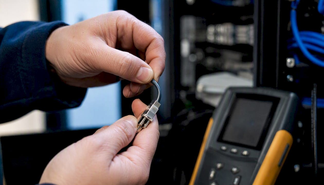
A run that passes a static wiremap but shows errors under traffic load needs a continuous-monitor test or a flex test. Physically flex each connector while the certifier runs continuously. A marginal crimp will show up as a momentary failure when the connector moves. This technique, described in the CrimpShop cable diagnosis field guide, catches the termination failures that static tests miss entirely.
Correlate time-of-day drops with HVAC cycles or equipment schedules. A run that fails only when the building heats up points to thermal expansion at a marginal termination, not a software problem.
What is the right fix: reterminate, repair, or replace?
The decision depends on five factors: test outcome, visible physical damage, run accessibility, expected remaining service life, and impact to critical services. The ITSIMM (8th edition) covers accepted field techniques for each remediation path.
Decision matrix
| Scenario | Recommended action | Estimated scope | Expected downtime |
|---|---|---|---|
| Marginal wiremap, intact jacket, accessible run | Reterminate connector or keystone | Per-port (low cost) | 15–60 minutes per port |
| Intermittent connector, no physical damage | Reterminate and flex-test | Per-port (low cost) | 15–60 minutes per port |
| Visible jacket damage, crushed section | Replace full run | Per-run (medium cost) | Half-day to full day per run |
| Multiple failed pairs, fails after retermination | Replace full run | Per-run (medium cost) | Half-day to full day per run |
| Fiber with high splice loss or crushed fiber | Splice repair or full replacement | Per-segment (medium to high) | 1–4 hours per segment |
| Backbone or multi-run failure, hazardous routing | Full backbone replacement | Multi-run (high cost) | Phased, 1–5 days |
When to reterminate: The run passes length and loss tests but shows a wiremap fault or marginal NEXT at one end. The jacket is intact, the run is accessible, and the fault is clearly at the termination point. Retermination is the lowest-cost fix and carries the shortest downtime.
When to replace the run: Visible physical damage anywhere along the route, multiple failed pairs, fiber with attenuation above the link budget, or a run that fails certification after a second retermination attempt. Runs routed through areas with ongoing water exposure, pest activity, or extreme thermal cycling are replacement candidates even if they currently pass, because they will fail again.
Testing and warranty after remediation: Every remediated run requires a certified test report. Require a channel warranty for full run replacements and a component warranty for reterminations. Why cable testing matters before returning a run to service is straightforward: an uncertified run has no defensible pass/fail baseline for future warranty claims.
How do you label and document so the fix actually sticks?
Remediation without documentation creates the same problem six months later. A technician who cannot identify which patch panel port connects to which wall jack will repeat the same diagnostic work from scratch.
Labeling convention to use:
- Unique cable ID (e.g., B2-PP01-P12-WJ-A204): building, panel, panel port, destination jack, room
- Origin and destination pair on both ends of the run
- Date of installation or remediation and technician initials
- Category and jacket type on runs where mixed categories exist in the same tray
For permanent thermal-transfer labels on patch panels and recessed wall jacks, the Cables and Chips cable labeling guide covers durable label materials and enterprise-friendly templates. Adhesive labels in ceiling or attic runs need UV-resistant stock rated for the temperature range of that space.
Essential documentation deliverables:
- Certified test reports saved by cable ID (file name matches the cable ID on the label)
- Port map in CSV or Visio format showing panel port, cable ID, and destination jack
- Rack elevations showing switch port assignments
- Cable routing diagrams for any new or rerouted runs
- Before-and-after photos of every remediated area
- Updated asset or CMDB reference with cable IDs
Tie each cable ID to the certifier report file name and store results in a centralized folder with search-friendly metadata (building, floor, date, technician). The structured cabling as-built documentation guide from Cables and Chips provides practical templates and recommended file formats for this archive.
For step-by-step patch panel labeling techniques, the patch panel labeling guide includes printable templates that map directly to port map formats.
Which standards govern remediation work?
Three documents define the minimum bar for any commercial remediation project in the United States.
ANSI/TIA-568 sets performance limits for structured cabling channels and components, defines permanent-link and channel test configurations, specifies T568A and T568B pinouts, and establishes maximum distances. Any run that does not meet TIA-568 limits after remediation has not been remediated, it has been touched.
ANSI/BICSI N1-2019 requires that all cabling work be performed in a “neat and workmanlike manner” and specifies minimum installation practices: bend radius compliance, proper cable dressing, labeling, and adherence to applicable codes including NEC. N1 is the standard to cite in your RFP acceptance criteria when you want to hold a contractor to professional installation quality, not just electrical continuity.
NEC (NFPA 70) governs the electrical code intersections that affect cabling work: plenum vs. riser jacket ratings, firestopping requirements after penetrations, and bonding/grounding where metal pathways interact with electrical systems. Any remediation that opens a fire-rated penetration must restore the firestop to the original listed assembly.
Practical best practices to include in every scope document:
- Maintain minimum bend radius (4x cable OD for Cat6, 10x for fiber) throughout the run
- Limit untwist at terminations to no more than 13 mm (0.5 in.) for Cat6
- Separate data and power runs where required by NEC or TIA-569
- Require documented firestopping procedures for any penetration work
- Specify the locally adopted NEC edition in the scope
- Require bonding and grounding checks where fiber or metal pathways interact with electrical systems
Standards callout: ANSI/BICSI N1-2019 defines “neat and workmanlike manner” as the minimum installation quality standard for all telecommunications cabling work, including remediation. Citing N1 by name in your RFP acceptance criteria gives you a contractual basis to reject work that is technically connected but professionally unacceptable.
Require BICSI-trained or certified technicians for any complex remediation. The BICSI Installation Handbook (v8) documents the core competencies those technicians must demonstrate, including copper and fiber termination, testing, and retrofit procedures.
How do you scope, stage, and budget a remediation project?
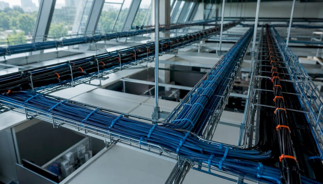
A well-scoped remediation project has eight bid line items: physical inspection, labeling, certified testing, retermination, run replacement, tray cleanup, abandoned cable removal, and as-built delivery. Missing any one of them creates a gap that shows up as a change order.
High-level cost guidance
| Scope | Cost band | Notes |
|---|---|---|
| Patch cord replacement | Low (per port) | Materials plus labor; no certification required |
| Keystone / connector retermination | Low to medium (per port) | Includes flex-test and certified report per port |
| Single-run replacement (outlet to panel) | Medium (per run) | Includes pull, terminate, certify, label, and document |
| Backbone or multi-run replacement | High (per segment) | Phased; includes tray work, firestopping, full certification |
| Fiber splice repair | Medium (per splice) | OTDR before and after; power-meter confirmation |
| Full fiber run replacement | High (per run) | Includes OTDR, power meter, and updated as-built |
Regional labor rates vary. New York City commercial projects carry higher labor costs than national averages, reflecting prevailing wage rates and building access requirements. Budget accordingly and get itemized bids that separate materials, labor, testing, and documentation.
For project-level best practices on staging and integrating new cabling with existing infrastructure, the network infrastructure renovation guide from Cables and Chips covers phased execution in detail.
Staging and risk controls:
- Phase critical services (access control, cameras, VoIP) first so any disruption happens during a planned window
- Schedule work during low-impact hours (nights, weekends) for mission-critical environments
- Provision temporary redundancy (a known-good patch cord on a spare switch port) for PoE devices before cutting over
- Require pre-certification of existing runs before work begins and post-certification of all remediated runs before sign-off
What ongoing maintenance prevents the next failure?
Remediation is not a one-time event. Without a maintenance cadence, the same problems recur within 18–36 months in high-change environments.
Recommended maintenance schedule:
- Monthly: Visual inspection of high-change spaces (open offices, server rooms with frequent MACs). Check for unsecured patch cords, new cable runs added without labeling, and tray overfill.
- Quarterly: Spot-check 10–15% of ports with a basic wiremap tester. Review switch port error counters for any port showing elevated CRC counts. Verify that new runs added since the last check are labeled and documented.
- Annually: Partial certification sampling of 20–25% of runs, rotating the sample each year so the full plant is covered over a 4–5 year cycle. Full certification after any major renovation or equipment refresh.
- After major MACs: Full certification of all affected runs before the new equipment goes live.
Operational controls that prevent degradation:
- Implement a MAC approval workflow. No new cable run or patch cord change without a work order that includes labeling and documentation requirements.
- Enforce labeling at installation. A run that goes in unlabeled will never get labeled retroactively.
- Limit tray access. Require a work order to open cable trays, and inspect for damage or overfill at each access.
- Restrict ad-hoc patching. Patch cords added without documentation are the single fastest way to destroy a clean port map.
Recordkeeping and monitoring:
Store certifier reports by cable ID in a centralized folder. Keep before-and-after photos indexed by date and area. Enable switch port logging for long-term trend analysis. A port that shows a gradual increase in CRC errors over six months is telling you a termination is degrading before it fails completely.
Brief every technician who touches the plant on the patch cord swap-and-test procedure and on how to escalate a marginal result to full certification. A 15-minute training script prevents the most common field mistake: replacing a run that only needed a patch cord.
Integrating change-control discipline with cybersecurity handoffs after remediation is covered in the cybersecurity workflow guide for contractors, which addresses how physical infrastructure changes should be logged and communicated to security teams.
How does a professional remediation project actually work?
The following describes the workflow Cables and Chips uses on commercial remediation projects in New York City. It reflects the deliverables and sequencing that produce a clean, documented result.
Project workflow:
- Initial triage: Site visit to confirm scope, review switch logs, and identify affected areas. Cables and Chips documents existing conditions with photos before any work begins.
- Prioritized remediation plan: Critical services (access control, cameras, VoIP) are scheduled first. A written scope with timeline and deliverables is provided before work starts.
- Retermination and run replacement: BICSI-trained technicians perform all termination and replacement work to ANSI/BICSI N1-2019 standards, maintaining bend radius, proper cable dressing, and consistent labeling throughout.
- Full certification: Every remediated run is tested with a Fluke Networks or NetAlly-class certifier in permanent-link mode. Results are saved by cable ID.
- As-built delivery: Cables and Chips delivers certified test reports, a port map in CSV format, rack elevations, and before-and-after photos at project close.
- Workmanship warranty: A written warranty covers all remediated channels.
Deliverables Cables and Chips provides on every project:
- Certified test reports (Fluke/NetAlly-class certifier output, saved by cable ID)
- Port map CSV and rack elevations
- Before-and-after photos of all remediated areas
- Updated as-built documentation
- Written workmanship warranty
Cables and Chips ties every certified test report to its cable ID so facility and IT teams can pull the exact test result for any port in under 60 seconds. That searchable archive is what makes future MACs faster and warranty claims defensible.
Outcomes to expect after a properly executed remediation:
- Elimination of scheduled and unscheduled link drops on remediated runs
- Restored PoE stability for cameras, access points, and VoIP phones
- A searchable test-report archive that supports future troubleshooting and vendor accountability
- Clean, labeled infrastructure that any qualified technician can work on without a site tour
What should you do this week?
If you have identified symptoms of failing cabling, these steps move you from reactive to controlled within a few days.
This week:
- Swap patch cords at the device and switch ends on every affected port. Use known-good cords only.
- Move affected devices to confirmed working switch ports and monitor for 24 hours.
- Pull switch port error counters and enable link-state logging on all affected ports.
- Run a basic wiremap test if you have a tester. Document the results.
- If problems persist after patch cord swap, schedule a permanent-link certification test.
Call a professional when:
- Intermittent drops persist after patch cord replacement
- Any run fails or shows marginal results on permanent-link certification
- Fiber runs show elevated attenuation or OTDR faults
- You need certified test reports and as-built documentation for a warranty claim or compliance audit
- The scope involves more than a handful of ports, or any mission-critical services are affected
What to request from Cables and Chips:
- BICSI-trained technicians for all termination and replacement work
- Certified test reports from a Fluke Networks or NetAlly-class certifier
- A written scope with timeline, deliverables, and warranty before work begins
Contact Cables and Chips at 20 Vesey Street, Lower Manhattan, to request a site assessment. Provide the approximate number of affected ports, the symptoms you have observed, and which critical services are involved. That information lets us scope the work accurately before the first visit.
Key Takeaways
Properly executed remediation requires standards-backed testing, a clear reterminate-vs-replace decision rule, and certified documentation delivered at project close.
| Point | Details |
|---|---|
| Swap patch cords first | Most intermittent drops resolve with a patch cord swap before any run replacement is needed. |
| Use permanent-link certification | Configure certifiers to permanent-link mode per ANSI/TIA-568 for a defensible pass/fail result. |
| Follow the decision matrix | Reterminate for marginal connector faults; replace the full run for physical damage or repeated failures. |
| Document with cable IDs | Tie every certified test report to its cable ID so future troubleshooting takes minutes, not hours. |
| Cables and Chips | Provides BICSI-trained technicians, certified test reports, port maps, and a written warranty on every NYC remediation project. |
Why certified remediation pays for itself
The most common mistake facility and IT managers make is treating cabling remediation as a repair job rather than a documentation project. A technician who fixes the fault but leaves no certified test report has given you a run that works today with no baseline for tomorrow. The next time that port flaps, you are starting the diagnostic process from zero.
Standards-based remediation, the kind that cites ANSI/TIA-568 performance limits and ANSI/BICSI N1-2019 installation practices in the scope document, changes that equation. You get a pass/fail record tied to a cable ID, a port map that any technician can read, and a warranty that is actually enforceable because the test report proves the work was done correctly.
The long-term value is straightforward: fewer repeat service calls, predictable maintenance budgets, and infrastructure that supports future upgrades without a full re-survey. When you add a floor, refresh your switching gear, or expand your PoE camera system, the as-built documentation from a properly executed remediation tells you exactly what you have and where it is. That is worth more than the cost of the certification test.
Cables and Chips remediates failing infrastructure in New York City
Your network is only as strong as the infrastructure behind it. Cables and Chips is a Lower Manhattan-based low voltage contractor with more than 40 years of experience remediating failing and disorganized cabling infrastructure for commercial offices, secure facilities, and enterprise environments across New York City.

Every remediation project includes a site assessment, BICSI-trained technicians, permanent-link certification with a Fluke Networks or NetAlly-class certifier, and a complete as-built package: certified test reports, port map CSV, rack elevations, and before-and-after photos. Work is backed by a written workmanship warranty.
To get started, request a site assessment through the structured CAT6 cabling installation page or review the full range of structured cabling system components Cables and Chips installs and services. Provide your site size, the symptoms you have observed, and which critical services are affected. We will respond with a written scope, timeline, and estimate before any work begins.
Useful sources
The following standards and references are worth citing directly in your RFP acceptance criteria and vendor scopes. Reference specific section numbers from TIA and BICSI documents to give your acceptance criteria contractual weight.
- ANSI/BICSI N1-2019, Installation Practices for Telecommunications and ICT Cabling and Related Cabling Infrastructure
- BICSI Installation Handbook (v8)
- Information Technology Systems Installation Methods Manual (ITSIMM, 8th edition)
- Intermittent Network Drops: Cable Diagnosis Field Guide (CrimpShop)
Save certifier report files with the cable ID in the file name and store them in a folder organized by building, floor, and date. When you write your RFP, cite ANSI/TIA-568 section numbers for performance limits and ANSI/BICSI N1-2019 for installation quality. That specificity gives you a contractual basis to reject work that does not meet the standard.
FAQ
What is cabling infrastructure?
Cabling infrastructure refers to the physical layer of a network: the structured copper and fiber runs, patch panels, cable trays, wall jacks, and telecom rooms (MDF/IDF) that carry data, voice, and power between devices and network equipment.
What happens when cables are not managed properly?
Unmanaged cabling leads to physical damage from tight bends, tray overfill, and accidental pulls, which causes intermittent link drops, PoE instability, and CRC errors that are difficult to diagnose and expensive to fix retroactively.
How do you improve cable management in an existing installation?
Start with a visual inspection to identify damaged runs, unlabeled cables, and tray overfill. Remove abandoned cables, install proper cable managers, label every run with a unique cable ID, and run a permanent-link certification test on all active runs to establish a documented baseline.
What are the risks of poor cable management?
Poor cable management increases the probability of physical damage to runs, makes troubleshooting slower and more expensive, creates fire hazards from abandoned cables in plenum spaces, and leaves you with no certified baseline to support warranty claims or future upgrades.
When should you call a professional to repair cabling systems?
Call a certified contractor when intermittent drops persist after patch cord replacement, when any run fails permanent-link certification, when fiber shows elevated attenuation, or when the scope involves mission-critical services and you need certified test reports and as-built documentation as deliverables.