
Rack Elevation Drawings: A Practical Guide for IT Teams

A rack elevation drawing is a scaled, 2D front and rear layout that shows every rack-mounted item in measured U positions so your team can verify fit, power capacity, cable paths, and service access before anyone touches a screwdriver. It solves three problems at once: procurement (does this switch actually fit where you planned it), capacity planning (space, power, and weight budgets), and maintenance (can a technician reach the PDU without unplugging six other devices).
A complete drawing package should include:
- A full equipment list with model numbers and U heights
- Front and rear U-position assignments
- Mounting depth and clearance notes
- PDU locations and cable entry points
Pro Tip: Rack diagrams document space, power, weight, and cabling together. Skip any one of those four and the drawing will mislead someone during installation.
Key Takeaways
Accurate rack elevation drawings prevent fit, power, and cable-routing failures by documenting exact U positions, mounting depth, and rear clearance before installation begins.
| Point | Details |
|---|---|
| Inventory before drawing | List exact U height, mounting depth, and weight for every device before assigning positions. |
| Document both views | Front elevations show installed gear; rear elevations show PDUs, managers, and service clearance. |
| Repeat patching patterns | Stack patch panel, manager, and switch in intervals instead of grouping all patching at one point. |
| Match tools to scale | Use draw.io for single racks, DCIM for multi-site tracking, AV-specific tools for appliance-heavy racks. |
| Treat drawings as living records | Cables and Chips builds as-built documentation and rack setup checklists that stay current after install. |
What Does a Rack Elevation Drawing Show?
A front elevation documents what a technician sees standing at the rack door: switches, servers, patch panels, and blanking panels in their assigned U slots. The rear elevation documents power distribution units, cable managers, rear cable entry, and the depth clearance needed to service power supplies or pull a transceiver. Most teams treat the front view as the “what’s installed” record and the rear view as the “can we actually service this” record, and the second one gets skipped far more often than it should.
You create elevations at a few predictable moments:
- New rack builds, before equipment ships, to catch depth or power conflicts early
- Retrofits, to plan around existing cabling and legacy gear you can’t move yet
- AV rack projects, where appliance depth and heat output vary wildly between units
- Handoffs between design and install teams, or between IT and a facilities crew
- Troubleshooting and future upgrades, when someone needs to know what’s actually in U22 without opening the door
Beyond the install itself, elevations feed directly into capacity planning. A drawing that tracks used versus available U space, circuit load per PDU, and cumulative rack weight becomes a live asset record, not just an install reference.
How Do You Create a Rack Elevation Drawing?
Building an accurate elevation is less about drafting skill and more about discipline in the inventory stage. Rushing that step is where most bad drawings start.
- Build a complete equipment inventory. List every device with its exact U height, mounting depth, and weight. Don’t round U height, and don’t guess depth. A device listed as “1U” that actually needs 1.5U of front clearance for cable bend will get flagged on-site instead of on paper.
- Measure the rack itself. Note usable depth, vertical mounting rail spacing, existing cable entry points top and bottom, and where PDUs can physically mount without blocking airflow.
- Assign U positions for both front and rear. Place heavy equipment low to keep the rack stable, and repeat the patch panel to horizontal manager to switch pattern at intervals rather than stacking all patching at the top.
- Document power and cabling detail. Map PDU breaker assignments, inlet and outlet orientation, service loop length, and your labeling convention for every port and jumper.
- Export your deliverables. A scaled PDF for the install crew, an editable native file for future revisions, and as-built documentation once the rack is live and verified.
Pro Tip: Document nominal U height alongside the practical clearance a module actually needs, like SFP cages or hot-swap power supplies. Nominal U alone almost always underestimates real service space.
What Belongs on Every Rack Elevation Checklist?
A drawing is only as useful as the detail behind each device entry. Every item should carry its model number, exact U height, mounting depth, weight, and front-or-rear orientation. Skip any of these and someone ends up measuring on-site instead of on paper, which defeats the purpose of drawing it in the first place.
Beyond individual devices, the checklist needs to cover:
- Patch panels, horizontal and vertical cable managers, blanking panels, shelves, and any accessory brackets or rail-mount hardware
- PDU mounting position, orientation, outlet mapping, and total power capacity per circuit
- Cable entry and exit points, labeling zones, service loop allowances, and clearance for pulling a power supply or transceiver without disturbing neighboring gear
Rack diagrams exist specifically to track space, power, weight, and cabling as a single system rather than four separate concerns, and a drawing that only tracks U space while ignoring power headroom or cable clearance will eventually cause a real installation conflict.
What Design Rules Keep a Rack Serviceable?
Airflow, cable routing, and service access aren’t separate concerns from the elevation itself. They’re the reason you drew it.
For airflow, leave strategic gaps between heat-generating equipment, install blanking panels in every unused U slot, and account for how your room’s cooling interacts with the cabinet’s own ventilation path. Full computational thermal modeling is rarely necessary for a standard rack. Basic blanking discipline and gap planning cover the vast majority of real-world cases; save deeper thermal analysis for high-density deployments where airflow genuinely gets complicated.
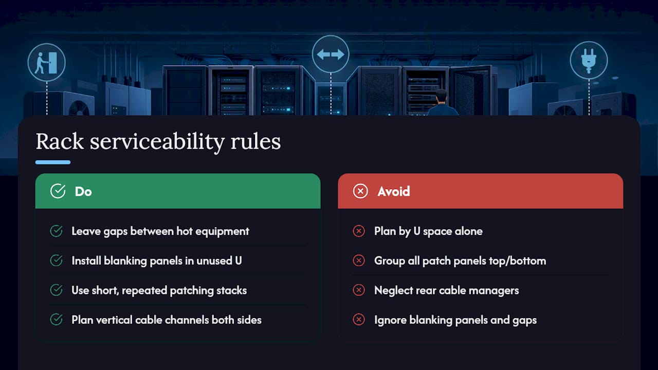
For cable routing, repeat short patching stacks instead of grouping all patch panels at the top or bottom of the rack. This keeps jumper lengths consistent and protects bend radius on fiber runs. Plan vertical cable channels on both sides of the rack, not just one.
For serviceability, keep heavy gear low, put frequently accessed equipment at a reachable height, and document rear clearance explicitly.
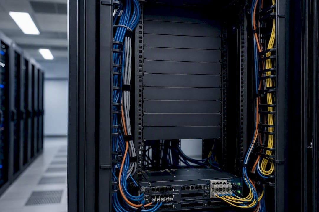
Pro Tip: The single most common mistake is planning by U space alone. A rack can have plenty of open U slots and still be impossible to service if nobody accounted for rear cable managers or true mounting depth.
Which Tools Should You Use to Draw Rack Elevations?
The right tool depends on scale, not preference. For a single rack or a small office buildout, draw.io templates or an editable SVG/Visio template get you a clean, scaled diagram fast, and they’re free.
Once you’re managing multiple sites or need continuous capacity tracking, a DCIM platform becomes worth the overhead. DCIM tools automate elevation updates as equipment changes, track power and space across an entire facility, and tie into broader data center asset management workflows that a static diagram can’t support alone.

For AV-heavy racks, purpose-built AV layout tools in the XTEN-AV category handle appliance-specific depth, heat, and labeling conventions that generic rack software often misses.
Whatever tool you choose, export both a scale PDF for field use and a native editable file, and treat the drawing as a living record rather than a one-time deliverable.
How Elevation Drawings Prevent Costly Installation Failures
A recent data center retrofit and rack cleanup illustrates the point well. The client’s existing racks had grown organically over years, with patch panels scattered across multiple cabinets and no documented rear clearance. Before any physical work began, the elevation drawing mapped every device’s actual U position and mounting depth against what existing labels claimed, exposing several mismatches.
The rear-view documentation caught two problems that would have caused delays mid-install:
- A PDU mounted too close to a rack rail, leaving no clearance for the intended cable manager
- Cable entry points that conflicted with planned switch placement
Working from a server rack setup checklist and producing as-built documentation afterward meant the next technician on-site had an accurate reference instead of guesswork.
Why Most Rack Drawings Skip the Part That Actually Matters
The front elevation gets all the attention because it’s what shows up in a proposal or a sales deck. The rear elevation, the one that documents PDU orientation, cable manager placement, and service clearance, gets treated as optional. That’s backward. Front-view drawings answer “does it fit.” Rear-view drawings answer “can anyone actually maintain this in eighteen months,” and that second question is the one that determines whether a rack ages gracefully or turns into a tangle nobody wants to touch.
The conventional advice to “plan your U space” isn’t wrong, it’s just incomplete. U space tells you nothing about whether a technician can pull a power supply without disturbing three other devices, or whether the labeling convention will still make sense to someone who wasn’t there for the original install.
If you take one thing from this guide, prioritize the rear view and the labeling discipline before you worry about aesthetic layout. A rack that looks clean from the front but undocumented from the back will cost someone hours during the first real incident.
— Ken
Get Your Rack Elevation Drawing Done Right the First Time
Drawing your own elevation with a free template works fine for a single rack you’ll only touch once. But if you’re managing multiple network closets, secure facilities, or a growing office buildout across New York City, Cables and Chips builds the elevation, installs the rack, and hands you as-built documentation that matches exactly what’s on the wall, not what a template assumed.

That means no gap between the drawing and the physical install, no scrambling later to figure out which PDU circuit feeds which switch, and no guessing about mounting depth on the next equipment refresh. Cables and Chips has spent more than 40 years handling structured cabling, server rack setup, and network closet cleanup for commercial clients throughout the city, so the documentation you get reflects real cable paths and real clearance measurements, not assumptions made from a spec sheet.
If your rack needs a build, a retrofit, or documentation that finally matches reality, request a site assessment from Cables and Chips and get a drawing that holds up on install day.
Sources
- What Is a Rack Elevation? | Data Center Glossary | Sunbird DCIM
- Rack Elevation Diagrams: Your Ultimate Guide – Graphical Networks
- How to Plan Rack Elevations That Work – NetPatch
- jgraph/drawio on GitHub
FAQ
What Is a Rack Elevation Diagram?
A rack elevation diagram is a scaled, 2D front or rear view of a cabinet showing every mounted device in its measured U position, used for planning fit, power, and cable routing before and after installation.
What Are the Rules for Drawing Rack Elevations?
Draw to scale using standard U measurements, document both front and rear views, place heavy equipment low, and record mounting depth and clearance for every device rather than relying on nominal U height alone.
What Software Can You Use to Create Rack Elevations?
Draw.io works well for single-rack or small-project diagrams, DCIM platforms handle automated, multi-site elevation tracking, and AV-focused tools like those in the XTEN-AV category suit appliance-heavy audio and video racks.
How Do You Create a Rack Diagram Step by Step?
Start with a complete equipment inventory that includes U height, mounting depth, and weight, measure the rack’s usable space, assign front and rear U positions, then document PDUs and cabling before exporting a scaled PDF and editable file.
Does Cables and Chips Provide Rack Documentation Services?
Yes, Cables and Chips produces as-built documentation and rack setup checklists for commercial clients throughout New York City as part of its structured cabling and server rack installation work.