
PoE++ Cabling Requirements: Cable, Length and Code
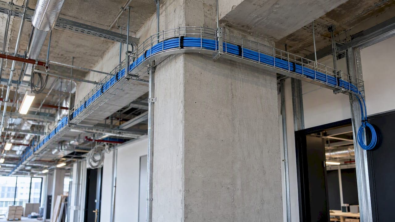
PoE++ does not need a special cable. It needs a four-pair twisted-pair channel that is installed, bundled and terminated well enough to carry up to 90 W of DC power without overheating or dropping voltage. The standard allows Category 5e as a floor. For new commercial work, we specify Category 6A, keep every channel within 100 meters (328 feet), and test the finished link.
This guide is for IT directors, facilities managers, general contractors and integrators who are cabling for PoE++ devices such as high-output access points, PTZ cameras, LED lighting, displays and door controllers. It covers the cable, the length, the heat, the code and the testing.
TL;DR
- PoE++ (IEEE 802.3bt) runs over standard four-pair Ethernet cable. Type 3 supports up to 60 W at the switch and Type 4 up to 90 W, and both use all four pairs.
- Category 5e is the stated minimum, but Category 6A is the sound choice for new installs because larger conductors run cooler under high current.
- The channel limit is still 100 m (328 ft): up to 90 m of permanent link plus patch cords. Higher power does not extend it.
- In the US, NEC Article 725.144, cable temperature rating, ambient temperature and bundle size decide whether a high-power run is safe.
- Test every PoE++ run after installation, including DC resistance and power under load, and keep the results with the as-built documentation.
What PoE++ is, and what it asks of the cable
PoE++ is the common name for IEEE 802.3bt. The amendment raises the power available to a powered device by using all four pairs of the structured wiring plant. Earlier PoE and PoE+ could work over two pairs. PoE++ Type 3 supports two- or four-pair cable, while Type 4 uses four-pair cable only, and the cable examples given there are ordinary Cat5 or Cat6 Ethernet.
The cable is the same family you already pull for desktops and access points. What changes is the margin. At 90 W, a marginal conductor, a long bundle or a poor termination turns into heat and voltage drop instead of a slow link.
| PoE++ Type 3 | PoE++ Type 4 | |
|---|---|---|
| Power at the switch (PSE) | Up to 60 W | Up to 90 W |
| Power at the device (PD) | Up to 51 W | Up to 73.2 W |
| Pairs used | Four | Four |
The figures come from TIA’s overview of Class 2 power in smart buildings. The gap between source and device is cable loss, which is why conductor quality matters. Switch output classes vary by model, and NETGEAR notes that 802.3bt equipment is backward-compatible with 802.3at and 802.3af devices, so one cabling plant can serve old and new devices together. For how these standards map to device classes, see our PoE standards guide for integrators.
Which cable category to use
The standard sets a floor, and good practice sets a higher bar.
- Floor: Category 5e is the minimum cable category for IEEE 802.3bt.
- Recommended: CommScope recommends Category 6 or 6A, preferably 6A, for four-pair PoE.
- For new 90 W work: Cisco recommends Category 6A or 7A four-pair cabling for new 90-watt installations for the best thermal and power efficiency. Leviton gives the same advice for new four-pair PoE, to improve reliability and manage temperature rise.
The reasoning is practical. Older, lower-category cable can carry PoE, but those designs are constrained by bundle size and temperature rise, which is why Category 6A is the preferred choice for reliable, future-proof enterprise installations. It is a design recommendation, not a claim that PoE++ needs a proprietary cable.
Category 6A also pays off beyond power. It supports 10GBASE-T, and it is what we point offices toward for Wi-Fi 6E and multi-gigabit access points. Cabling a ceiling once for both power and speed is cheaper than opening it twice.
If you already have Cat5e
Existing Cat5e is not automatically a problem. It depends on the length, the bundle and the load. We test existing runs first, and where they fall short we replace only the problem runs. Our write-up on PoE over Cat5e failing near 90 meters shows where those failures show up, and our guide to replacing outdated Cat5 with Cat6 covers how to phase the work.
Four-pair wiring and pinout
Because PoE++ uses all four pairs, every one of the eight conductors has to be intact. A link that passes at 100 Mbps on two pairs can still fail a PoE++ load. Common causes:
- A split or poorly punched pair at the jack.
- A patch cord with only four conductors wired.
- A connector or panel not rated for the planned power.
- Different resistance between pairs or between wires in a pair, which can degrade performance and stop the link delivering full power.
That last point is why a wiremap alone is not enough. A link can be electrically continuous and still unbalanced.
The 100-meter limit does not move
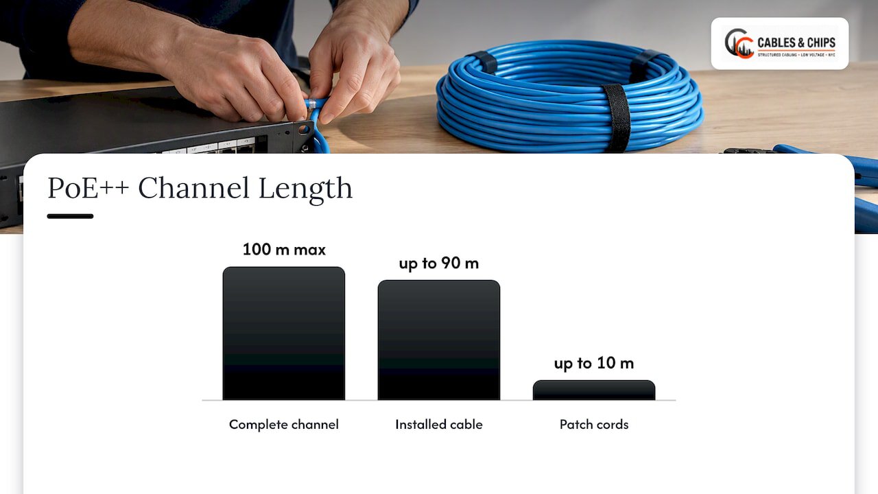
The standard maximum run for PoE++ is 100 meters. In practice the complete channel stays within 100 m (about 328 ft), which normally means up to 90 m of installed cable plus up to 10 m of combined patch cords. Moving from Cat5e to Cat6 or Cat6A does not extend that distance.
Some specialized cables with larger copper conductors, for example 22 AWG, may technically carry power past 100 m. Those runs do not comply with industry standards, so we do not design them into commercial projects. The compliant answer for a device 300 feet away is a second telecom closet or a fiber link to a remote switch, not a longer copper run. If you want the full reasoning, read our pieces on the 90/5/5 rule and on why 100 meters is a ceiling.
Plan for the real length, not the floor plan length
In Manhattan buildings, cable rarely goes in a straight line. Add vertical drops, slack at both ends, routing around structure, and service loops in the ceiling. A device that is 70 m away on a plan can be 95 m of cable. Measure the pathway, not the drawing, and give yourself margin below 90 m on the permanent link.
Conductor size, heat and why 6A runs cooler
Current heats copper. The thinner the conductor and the tighter the bundle, the more heat builds, and the center of a large bundle is the hottest spot. Higher resistance also means more of the 90 W source power is lost before it reaches the device.
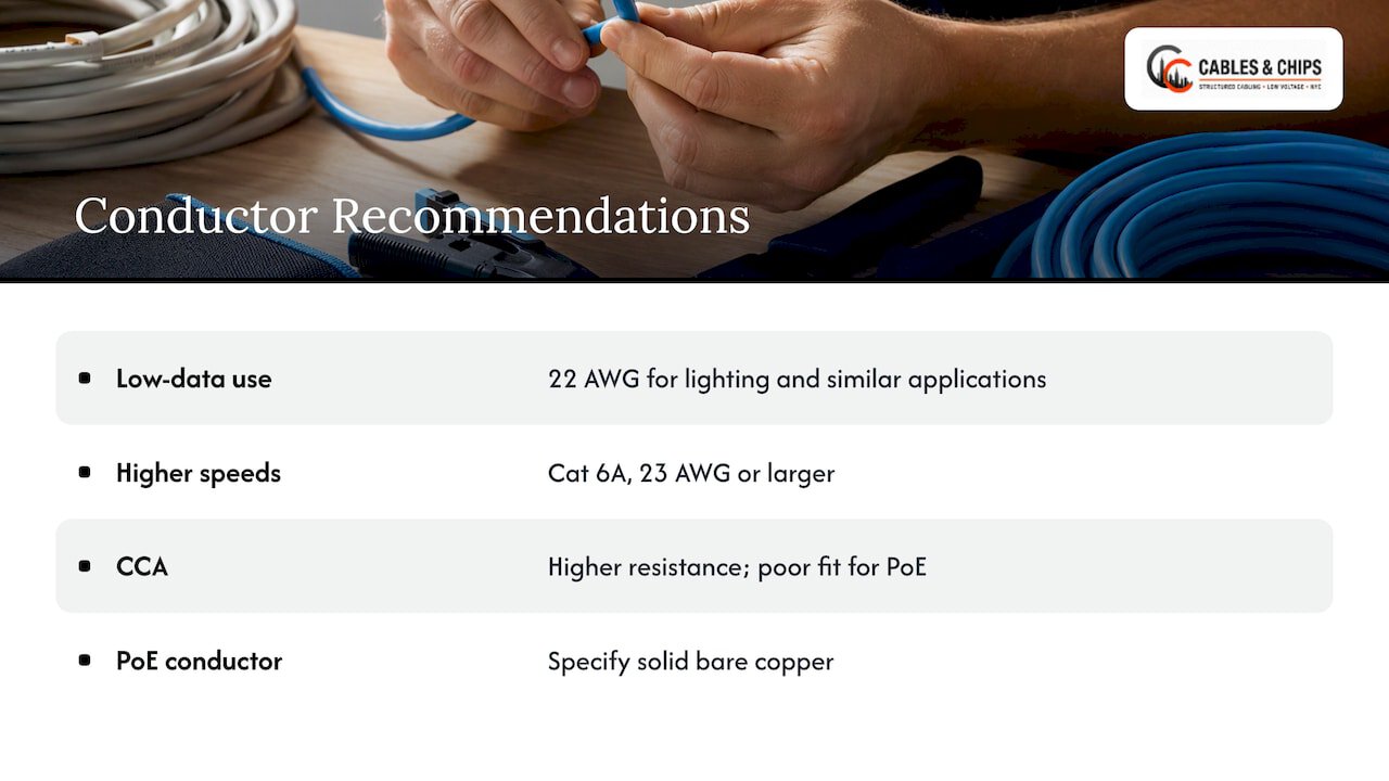
Cisco’s guidance for Type 4 is to use 22 AWG conductors for lighting and other low-data-speed applications, and Cat 6A with 23 AWG or larger conductors for higher data speeds. Leviton’s view is that larger conductors generally handle current with less temperature rise, which is the engineering reason behind the Category 6A recommendation.
Watch out for copper-clad aluminum (CCA). It has higher resistance than solid copper, and it is a poor fit for PoE. Specify solid bare copper and check the jacket print and the supplier’s documentation before the reel goes on site.
Conductor size and run length also shape performance for non-PoE users. If you want a plain-language look at how conductor size and run length affect real traffic, this Cat6 Ethernet cable shortlist walks through a simple speed test you can use on a finished link.
For lighting and other low-data devices, our article on Cat6A 22 AWG PoE lighting cabling goes deeper on gauge and voltage drop.
Bundling, temperature and the NEC
This is where PoE++ jobs most often go wrong, because the problem is invisible on day one.
In the US, commercial installations must follow NEC Article 725.144 for ampacity and temperature limits, and bundle layout and pathway type should follow TIA TSB-184-A guidance to prevent heat build-up in the middle of bundles. The Ethernet Alliance explains that conductor gauge, cable temperature rating, ambient temperature and bundle size matter for Type 3 and Type 4 installations.
What that means on a job:
- Ampacity is rated at 30°C (86°F). Specified cable types must meet their limits at that temperature, and correction factors apply above it. Plenum spaces, risers and ceilings above kitchens or mechanical rooms can run warmer.
- Bundle size matters. Large bundles of cables all carrying 90 W retain more heat than small ones. Break a big home-run bundle into smaller groups, or choose a cable rated for the load.
- Look for the -LP marking. The NEC permits specified cable types with an “-LP” suffix to supply power up to the ampere limit marked after it and to carry data. An LP-listed cable gives the inspector and the building a clear answer on bundle limits.
- Pick the jacket for the space. Plenum, riser and general-purpose ratings still apply, in addition to the power rating.
Local requirements and the authority having jurisdiction decide the final call. In New York City, we confirm requirements with the building and the project’s electrical engineer before ordering cable.
Pathways, spaces and terminations
Pathways and spaces are the unglamorous half of a heat-safe design. ANSI/TIA-568-C.1 and ANSI/TIA-569-B provide the foundational installation requirements for pathways and spaces that reliable power delivery over twisted pair depends on. In practice:
- Use cable trays and J-hooks sized so that bundles are not packed against each other or against warm equipment.
- Keep bend radius and pull tension within the cable’s rating. Damage from a hard pull can raise resistance in one pair.
- Avoid tight cable ties that squeeze the bundle; use hook-and-loop straps.
- Label both ends and document pathway for each run.
Connectors, jacks and patch panels
The cable is only part of the channel. For PoE++, jacks, panels, patch cords, plugs and other connecting components should be suitable for the planned power rating. Mating and unmating contacts under load can arc, so use quality components throughout and avoid mixing unrated patch cords into a high-power channel. Poor terminations add resistance, and excess DC resistance unbalance can cause bit errors, retransmissions or a link that does not work at all.
Our server rack and network closet work matters here too: a tidy closet with documented patch panels makes it far easier to trace a failing PoE port to a bad patch rather than a bad run.
Testing and documenting a PoE++ run
Certification proves the cable meets its category. PoE testing proves the link can deliver power. We treat both as part of the install, not an optional extra.
Modern field testers can test PoE under load to determine the power available at the jack, including the PSE type, pairs used and allocated power. Some also support load testing, PSE configuration details, external load monitoring and DC resistance unbalance measurements, and results can be stored and reported.
A complete handover package for a PoE++ run includes:
- Category certification results for each link (length, wiremap, insertion loss, crosstalk).
- DC resistance and resistance unbalance for PoE runs.
- Power available under load at the jack for high-power devices.
- Labeled as-built drawings and patch panel maps.
- The cable type, rating and LP marking used, so the next contractor knows what is in the ceiling.
When something fails six months later, this record turns a guess into a ten-minute diagnosis.
Budgeting power at the switch
Cabling that can carry 90 W does not mean the switch can supply 90 W on every port. A 24-port switch with a fixed power supply may support only a few Type 4 devices at once. Add up the device classes, include a buffer, and size the PSU before you buy. We show a worked example in our PoE power budget guide for IT teams. For wireless, our access point PoE requirements article shows why many access points need far less than Type 4. For cameras, see our guidance on CCTV cable types and the 100 m PoE limit.
Our perspective
After more than 40 years of working in New York commercial buildings, we see the same pattern with PoE: the switch gets all the attention, and the cabling gets whatever is left in the budget. Then a ceiling full of high-power devices runs warm, a few runs come in at 94 meters, and the building pays to open the ceiling again.
Our approach is simple. We specify Category 6A for new PoE++ work, we keep permanent links comfortably inside 90 meters, we split bundles that are too large, and we test every run for more than pass or fail. We hand over documentation so that your IT team or the next integrator can see what was installed and how it performed.
Your network is only as strong as the infrastructure behind it. PoE++ raises the stakes because the cable is now part of the power system. A clean, documented, tested install is the cheapest way to avoid a callback.
Ken
A practical checklist before you pull cable
- List every PoE++ device with its power class and location.
- Measure real cable paths and mark any run above 90 m for a closet relocation or fiber.
- Choose Category 6A, solid copper, with an LP marking where the bundle size calls for it.
- Check the ambient temperature of each pathway and plan bundle sizes accordingly.
- Select jacks, panels and patch cords rated for the planned power.
- Confirm the switch PSU and per-port budget.
- Test with a PoE-capable tester and store the results with your as-built drawings.
For offices building a new floor, our structured CAT6 and CAT6A installation work follows this sequence from the start.
Cabling PoE++ in New York City
Cables & Chips is a low voltage and data network contractor at 20 Vesey Street in Lower Manhattan. We design, install, test and document structured cabling for commercial offices, secure facilities and enterprise environments across New York City. That covers CAT6 and CAT6A, WiFi access point cabling, CCTV and access control cabling, and network closet cleanup. We offer a no-obligation site survey, and we can check existing runs before you commit to new cable.
If you are planning PoE++ devices, schedule a site survey through our services page and we will walk the pathways, test what is in place and give you a documented plan. You can also start at cables.nyc.
FAQ
What cable does PoE++ require?
PoE++ runs over standard four-pair twisted-pair Ethernet cable. Category 5e is the minimum stated for IEEE 802.3bt, and Category 6A is recommended for new installations because it handles heat better at high current. No proprietary cable is needed.
Can I run PoE++ over Cat5e?
Yes, for short, lightly bundled runs with good terminations, Cat5e can work. It has less margin for temperature rise and resistance, so long runs and large bundles are where it fails first. Test existing Cat5e before you rely on it for 60 W or 90 W devices.
How long can a PoE++ cable run be?
The limit is 100 meters (about 328 feet) for the whole channel, normally 90 m of permanent cable plus up to 10 m of patch cords. Using Cat6 or Cat6A does not extend that distance. For longer distances, add a closet with a switch or use fiber to a remote switch.
Does PoE++ cable need to be shielded?
The research we relied on does not make shielding a PoE++ requirement. Category and conductor size, bundle layout and termination quality matter more for power delivery. Choose shielded or unshielded based on the environment and the data requirements, and ask us during the site survey if the space has heavy electrical interference.
How should PoE++ runs be tested?
Use a tester that can check power under load, DC resistance and resistance unbalance, in addition to standard category certification. Keep the results with the as-built documentation so any future problem can be compared against the original baseline.
Sources
- IEEE SA: IEEE 802.3-2022
- IEEE 802.3bt Features
- TIA: A Closer Look at Class 2 Power in Smart Buildings
- NETGEAR: Power over Ethernet (PoE) standards and compatibility
- Cisco: UPOE+ and IT-OT Convergence
- CommScope: Power Over Ethernet Topics and Technologies
- CommScope: PoE Implementation Guide
- Leviton: Cabling and Connectivity for Power over Ethernet
- Just Add Power: Ethernet Cable Requirements
- Cisco Catalyst 9400 Hardware Installation Guide
- Ethernet Alliance: Cabling-System Design and Installation for Delivering Power via PoE
- IEEE 802.3bt Guidelines for Field Deployment
- Cabling Installation & Maintenance: Trends and future directions in network infrastructure testing
- MAG Kabel: PoE, PoE+ and PoE++
- Fluke Networks: A Guide to Successful Installation of Power over Ethernet
- Cat6 Ethernet cable shortlist and speed test