
Stock Six Patch Cord Lengths IT Pros Use to Fit Every Rack

Choose the shortest stocked patch cord that covers the measured cord path plus a small service loop, not the longest one within reach. ANSI/TIA-568 sets a 10 m (33 ft) total channel allowance for patch, work area, and equipment cords, and that number is your compliance ceiling, not your target. For most cabinets, stocking six lengths, roughly 6 in, 1 ft, 3 ft, 5 ft, 7 ft, and 15 ft, covers nearly every run you will encounter.
TL;DR:
- Patch cords should be selected based on the actual routed distance plus slack, with common sizes covering 6 inches to 15 feet for most rack scenarios.
- Measure the cable path through managers and turns rather than straight-line distances, adding about 6 to 12 inches for dressing and slack.
- The ANSI/TIA-568 standard limits the total length of patch, work area, and equipment cords combined to 10 meters (33 feet), with practical use segments typically under 5 meters (16 feet).
- For copper cables, length beyond 15 to 20 feet is usually better as a fixed horizontal run; fiber cords can be longer but must allow for gentle bends to prevent attenuation.
- Maintaining standardized stocked lengths and proper cable management practices minimizes correction and troubleshooting issues over time.
What Is the Right Patch Cord Length for a Rack?
There is no single correct patch cord length across an entire facility. The right length is whatever matches the actual routed distance between two ports, plus enough slack to service the connection without tension on the connector. That means the answer changes cabinet by cabinet, and even port by port, depending on where equipment sits and how your managers route cable.
What stays constant is the method. Measure the path the cable will actually travel, not the straight line between two jacks. Round up to the next stocked size. Leave a small, deliberate loop instead of pulling the cord taut.
Facilities managers often ask for a single “standard” length to simplify procurement, and that instinct is not wrong, it just needs boundaries. A site can standardize on a handful of lengths and still fit every port, provided the stocked set spans short adjacent jumps through long cross rack runs. The goal is fewer SKUs, not one SKU.
Standard Stocked Patch Cord Lengths and Where Each Belongs
Manufacturers and distributors settled on a common set of factory lengths because they map cleanly onto rack geometry. Vendor guidance on stocked length mapping ties each size to a typical use case, which saves you from custom-cutting cable for every port.
| Stocked Length | Metric Equivalent | Typical Use | Watch For |
|---|---|---|---|
| 6 in | 15 cm | Adjacent 1U patch panel to switch port | Too short if the panel and switch sit in different vertical planes |
| 1 ft | 30 cm | Same-U or one-U offset jumps | Common default for dense top-of-rack switching |
| 3 ft | 90 cm | Cross-rack jumps, patch panel to mid-rack switch | Add length if a horizontal manager sits in the path |
| 5 ft | 1.5 m | Half-rack verticals, panel to switch two or three U away | Watch bend radius at the connector boot |
| 7 to 10 ft | 2 to 3 m | Full-rack drops, top-of-cabinet to bottom-of-cabinet runs | Needs a vertical manager pass; budget extra for dressing |
| 12 to 20 ft | 3.6 to 6 m | Cross-cabinet runs, adjacent rack rows, overhead tray routing | Approaching the point where a fixed horizontal run makes more sense than a patch cord |
When a measured run lands between two rows on that table, order the longer one. A cord under slight tension will eventually pull on a connector or a port, and that strain shows up later as intermittent link drops, not an immediate failure. The extra six or twelve inches costs nothing compared to a truck roll.
How Do You Measure a Patch Cord Path Correctly?
Straight-line distance is the wrong number almost every time. A cable does not travel through the rack as the crow flies. It exits a patch panel, drops into a vertical manager, turns through a horizontal manager, crosses the front of the cabinet, and enters the switch port from whatever angle the manufacturer built into that chassis. Each of those transitions adds real, physical length that a tape measure across open air will never capture, a point confirmed in technical discussions of TIA cord length practice.
Rack U math gives you a repeatable starting point. One rack unit equals 1.75 inches, so a patch panel in U12 connecting to a switch in U18 spans six units, or 10.5 inches of vertical travel before you account for horizontal offset, manager entries, or slack. A worked example: panel at U12, switch at U20, eight units apart (14 inches), routed through one vertical manager pass (add roughly 6 to 12 inches for dressing), plus a 4 inch service loop at each end. That totals somewhere around 26 to 34 inches, which rounds up to a 3 ft stocked cord rather than a 2 ft one that would sit under tension.
Four variables consistently get missed on a tape measure:
- Manager passes. Every horizontal or vertical manager entry and exit adds dress length beyond the raw distance.
- Port offset. A port near the edge of a panel travels a different path than one near the center, even on the same panel.
- Bundle edge travel. A cable riding the outside of a bundle covers more distance than one riding the inside curve.
- Slack and bend radius. Service loops and the minimum bend radius at each connector both add length that a straight measurement ignores.
On-site, run this checklist before pulling a single cord: identify the exact panel port and switch port; count rack units between them and convert to inches; trace the physical path through every manager it will cross; add dress length per manager pass; add a 3 to 6 inch service loop per end; compare the total against your stocked lengths and round up. A cable slack management approach built around this checklist keeps techs from grabbing whatever length is closest at hand.
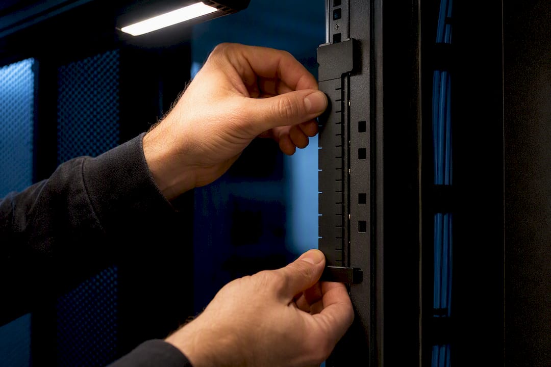
Pro Tip: Keep a $10 rack ruler or a printed U-to-inch conversion card in your tool bag. Eyeballing rack unit counts under a deadline is where most undersized patch cord orders come from.
What Do ANSI/TIA Standards Actually Limit?
ANSI/TIA-568 caps the combined length of patch cords, work area cords, and equipment cords in a horizontal channel at 10 m (33 ft) total, and many implementations further treat 5 m (16 ft) as the practical guidance for an individual patch or jumper segment, according to the ANSI/TIA-568 commercial building cabling standard. That total channel number, not any single cord’s length, is what compliance testing actually checks.
A few numbers to keep straight:
- 10 m (33 ft): total allowance for patch cords, work area cords, and equipment cords combined in a horizontal channel.
- 5 m (16 ft): commonly referenced practical limit for a single patch or jumper segment in many deployments.
- 20 m (66 ft): typical cap for cross-connect jumpers at main or intermediate cross-connect points, per ANSI/TIA-568.
- 30 m (98 ft): allowed for equipment connections back to a cross-connect in some topologies.
MUTOA (multi-user telecommunications outlet assembly) deployments change this math further. Anixter’s standards documentation on MUTOA derating and cord length calculation explains that MUTOA layouts require a derating formula tied to the horizontal cable length feeding them, which can permit longer combined cord runs than the flat 10 m rule assumes. If your facility uses MUTOAs, do not eyeball this; run the calculation.
Even where the standard technically allows a longer cord, choose the shorter one anyway whenever both options fit the physical layout. A 5 m cord run inside a 10 m budget leaves almost no headroom for horizontal cable, work area cords, or equipment cords elsewhere in that same channel, and a marginal channel is a channel that fails certification testing the next time someone adds a device.
Which Patch Cord Length Fits Your Rack Scenario?
Different topologies call for different defaults, and a patch panel sitting one rack unit from its switch needs a very different cord than one fifteen units away.
- Adjacent patching (same U or one U apart): 6 in to 1 ft. This is the majority case in a well-planned top-of-rack switching layout.
- Same-U offset across the panel width: 1 ft to 1.5 ft, since the horizontal travel adds up even when the vertical distance is zero.
- Panel-to-switch, several U apart: 3 ft to 5 ft, depending on manager passes.
- Half-rack vertical runs: 5 ft to 7 ft.
- Full-rack or cross-cabinet runs: 7 ft to 15 ft, with 20 ft reserved for adjacent rack rows or overhead tray routing.
- Fiber uplinks between switches or to a core: size the same way as copper, but add working length through managers to protect the connector’s bend radius.
Choose stranded conductor patch cords for anything living inside a rack. Stranded copper flexes repeatedly without fatigue, which is exactly what a cord routed through managers and reseated occasionally needs, while solid conductor cable belongs in permanent horizontal runs between the panel and the wall jack, a distinction Belden’s structured cabling reference draws clearly.
Longer cords, once necessary, need mitigation, not just length. Route them through a dedicated manager path rather than draping them across open rack space, secure them with velcro tie points instead of zip ties that crush the jacket, and label both ends before the cord goes into service. A rack that grows past a dozen 15 ft and 20 ft runs without a labeling discipline turns into a troubleshooting problem the first time someone needs to trace a single link during an outage.
How Does Cable Management Change Your Length Choices?
Cable management is not cosmetic, it directly changes what length you need to order. A service loop of 3 to 6 inches at each termination point gives you enough slack to reseat a connector or move a device slightly without re-terminating the run, but a loop stacked too large in front of a switch blocks airflow and traps heat against the faceplate.
Bend radius matters more than most techs assume. Thicker cable jackets, particularly CAT6A and shielded variants, have a larger minimum bend radius, and forcing a tight turn to save six inches of cord length shortens the cable’s service life and can degrade its electrical performance.
Bundle position affects your math too. A cable riding the outer edge of a bundle through a manager travels farther than one riding the inner curve, an effect confirmed by bundle-effect guidance on length calculation. On dense runs, add slack for outer-bundle cords rather than assuming every cable in a group needs the same length.
A practical routine on installation day:
- Route and dress the horizontal cable managers first, before pulling any patch cords.
- Measure remaining panel-to-switch distances with managers in their final position.
- Add service loop allowance per end (3 to 6 inches typical).
- Select the next stocked length up from that total.
- Label both ends with panel port and destination before connecting.
- Log the length and location in your rack documentation system.
Pro Tip: Color-code patch cords by function, one color for user VLANs, another for management, another for uplinks, and your future self will thank you during a 2 AM outage call.
How Should You Stock and Order Patch Cords?
A minimal stocked set beats a warehouse of custom lengths. For a typical 42U cabinet population, start with roughly twenty 1 ft cords, fifteen 3 ft cords, ten 5 ft cords, eight 7 ft cords, and five 15 ft cords, then adjust based on your actual port count and topology after the first install pass.
Procurement checklist for whatever you order:
- Confirm stranded conductor construction for anything routing through managers.
- Match jacket rating to the space: plenum or LSZH (low smoke zero halogen) for above-ceiling or air-handling spaces, PVC for enclosed cabinets where local code allows it.
- Check the vendor’s return and warranty terms before bulk-ordering a new length you have not used before.
- Require length markings on the jacket itself, not just the packaging, so techs can identify a cord already in service.
If a calculated run lands between two stocked sizes, order the larger one and plan for a small service loop rather than a taut connection, a rule vendor sizing guidance applies consistently across rack layouts. A few extra inches of slack costs nothing. A cord pulled tight against a connector boot eventually fails at the worst possible time.
Fiber vs Copper: How Far Can Each Patch Cord Realistically Run?
Copper patch cords inside a rack rarely need to exceed 15 to 20 ft before the smarter move is a fixed horizontal run instead of a flexible jumper. Beyond that length, copper’s practical use case shifts from rack-to-rack patching to genuine backbone runs, which fall under different cabling categories entirely.
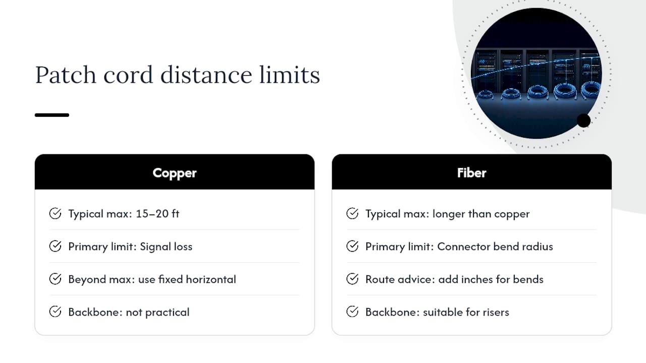
Fiber patch cords handle far longer distances without the same signal degradation concerns that limit copper, since attenuation over a patch-length fiber jumper is negligible at the distances found inside a data center or telecom room. The practical constraint on fiber is not signal loss, it is connector protection. Connector-level guidance on fiber patching points out that fiber cords need working length through cable managers specifically to avoid tight bends at the connector boot, since a fiber strand bent past its minimum radius suffers permanent attenuation loss, not just temporary signal degradation like copper might tolerate.
That means a fiber uplink between two switches often runs slightly longer than the equivalent copper jumper would, purely to give the strand room to curve gently through a manager rather than turn sharply at the connector. Size fiber cords the same way you size copper, by measuring the actual routed path, but add a few extra inches specifically for bend-radius protection at each end.
For genuine backbone or riser runs between floors or telecom rooms, fiber is the only realistic option regardless of distance, since copper’s usable length for data transmission tops out well before most building risers do.
Do 1 Gbps and 10 Gbps Networks Need Different Patch Cord Lengths?
The ANSI/TIA channel limits do not change based on network speed, but the margin for error shrinks considerably as speed increases. A 10 Gbps link over copper is far less tolerant of a marginal channel than a 1 Gbps link running the same cabling.
At 1 Gbps, a patch cord that is a few feet longer than ideal, or a channel running close to its total length budget, rarely causes a visible problem. The signal margin built into Gigabit Ethernet over CAT6 or CAT6A absorbs minor inefficiencies without measurable packet loss.
At 10 Gbps, particularly over CAT6A, the channel’s total length budget and the quality of every termination in that path start to matter in ways that show up as retransmissions, reduced throughput, or intermittent negotiation drops rather than a clean failure. A channel sitting near the 10 m (33 ft) total allowance for patch and equipment cords has far less headroom at 10 Gbps than the same channel running Gigabit traffic.
The practical takeaway for anyone speccing a 10 Gbps deployment: size patch cords conservatively, keep the total channel length well under the ceiling rather than pushing toward it, and treat every connector and bend as a potential source of insertion loss that a slower network would have simply absorbed. Higher speeds do not change how you measure a patch cord path, but they raise the cost of getting that measurement wrong.
How Do Temperature, Humidity, and Interference Affect Patch Cord Length?
Environmental conditions do not change the ANSI/TIA length limits, but they do change how much margin you should leave inside those limits. A telecom room running hot, poorly ventilated, or subject to temperature swings puts additional stress on cable jackets and connector boots, and a patch cord installed under slight tension in a cool room can tighten further as temperatures rise, since most jacket materials contract somewhat as they cool and expand as they warm.
Humidity matters most for cable near exterior walls, loading docks, or spaces without consistent climate control. Moisture exposure over time can affect connector contacts and jacket integrity, which is one more reason to avoid running patch cords under tension. A loose service loop gives a cable room to move slightly with material expansion and contraction without stressing the termination.
Electromagnetic interference does not directly change how long a patch cord should be, but it does change your routing decisions, which in turn affects the measured length. Keeping copper patch cords away from fluorescent ballasts, motors, and high-current conduit runs sometimes means a slightly longer route around an interference source rather than a shorter straight line through it. Fiber patch cords sidestep this concern entirely, since fiber carries light, not electrical signal, and interference sources that would degrade copper have no effect on it.
Facilities in industrial spaces, near elevator machine rooms, or in older buildings with less predictable electrical infrastructure should factor interference avoidance into the routing path before finalizing a length calculation, not after installation reveals a problem.
Why Does Cable Construction Quality Affect Patch Cord Length Choices?
Cheaply constructed patch cords fail in ways that make length calculations moot. A jacket with poor stranded conductor quality or thin insulation loses flexibility faster, which means a cord that fit its routing path cleanly on day one develops stress points at bends within a year or two.
Connector quality matters as much as cable quality. A poorly molded boot or a loosely crimped plug concentrates stress exactly where a cord is most likely to be flexed during service, at the point it exits the connector housing. That stress point is where undersized service loops cause the most damage, since a cord under tension transfers that tension directly to the weakest part of its construction.
Bend radius tolerance also varies by construction quality. Higher-quality CAT6A cords with better internal geometry tolerate tighter bends without performance loss than budget cable with poor conductor separation, which means your length calculations for manager routing may need extra slack specifically to compensate for lower-grade cable, even when the standard’s length limits are not in question.
The practical implication for stocking decisions: a slightly higher per-unit cost on quality patch cords often reduces the total length you need to stock, since better cords tolerate the tighter, more efficient routing paths that come from proper cable management rather than requiring generous slack to protect against premature jacket or connector failure.
An Installer’s Perspective on Getting Patch Cord Length Right
Most patch cord problems trace back to skipped measurement, not bad math. Techs grab whatever length is closest at hand under deadline pressure, and that habit builds racks full of tension points and tangled slack over years of moves and adds. Standardize a stocked length set per site and enforce a change-order step before anyone pulls a nonstandard cord. That single discipline, more than any calculator, is what keeps a cabinet clean five years after the original install.
— Ken
A professional structured cabling provider builds systems with this exact discipline: measured routing paths, standardized stocked lengths, and documentation that survives staff turnover. If your cabinets are running on guesswork instead of a length plan, our structured cabling system guide walks through the components worth getting right from the start, and our team can handle CAT6 and CAT6A installation for offices and secure facilities that need it done once and documented properly. Low Voltage. High Performance.
Sources
- ANSI/TIA-568 commercial building telecommunications cabling standard (excerpt)
- Patch cable length calculator and practical length mapping
- Patch Cables Go the (Shorter) Distance
- Belden copper structured cabling reference (excerpt)
FAQ
How Long Should a Patch Cable Be?
Use the shortest stocked length that covers the measured routing path plus a small service loop, typically 6 in to 5 ft for most in-rack connections, staying well under the 10 m (33 ft) total channel allowance set by ANSI/TIA-568.
What Is the Maximum Length of a Fiber Patch Cord?
Fiber patch cords do not face the same signal-loss distance constraints as copper at rack scale, so the practical limit is set by connector bend-radius protection and cable management rather than a hard maximum length.
Why Are Patch Cables So Short?
Shorter patch cables reduce clutter, improve airflow around patch panels and switches, and keep labels visible, which is why industry guidance favors stocking sets that run from a few inches up to about 20 ft rather than defaulting to long cords.
Is 100 Feet Too Long for an Ethernet Cable?
Yes, in most cases. A very long run exceeds the practical patch cord range entirely and approaches the horizontal cable distance limits themselves, so such a run should be a fixed horizontal cable run terminated at both ends, not a flexible patch cord.
How Do I Calculate the Right Patch Cord Length for a Rack?
Convert the rack unit distance between ports to inches using 1U equals 1.75 inches, add dress length for every manager pass in the path, add a 3 to 6 inch service loop per end, then round up to the next stocked size.