
40+ Years of Field Proven OTDR Testing for Fiber Technicians

An OTDR is a single-ended tester that maps where loss and reflections occur along a fiber, giving technicians a visual trace of every connector, splice, and bend between the transmitter and the far end. Use it for fault location, event characterization, and Tier 2 troubleshooting. For final insertion-loss pass/fail against a project’s loss budget, an OLTS remains the required tool.
TL;DR:
- Using an OTDR requires selecting proper dynamic range and pulse width to ensure accurate detection of long distances and closely spaced events.
- Bidirectional testing is essential to accurately determine splice loss and distinguish real faults from artifacts like ghosts.
- Proper setup involves cleaning connectors, attaching launch and receive cords, and verifying settings before testing to avoid false readings.
- Recognizing trace signatures such as reflective spikes, non-reflective steps, and ghosts helps identify specific fiber faults or issues.
- Final certification should always include detailed documentation, trace files, and notes on settings to ensure reliable troubleshooting and future reference.
What Does OTDR Testing Actually Measure?
An OTDR sends laser pulses down a fiber and reads what comes back. Two physical effects drive every measurement: Rayleigh backscatter, the faint light scattered continuously along the glass, and Fresnel reflection, the sharp bounce that occurs wherever the fiber meets air, a connector, or a break. Together they let the instrument build a complete loss profile of the link from one end, without anyone touching the far side.
The single-ended nature is the real advantage. A technician standing in a telecom closet on the 30th floor doesn’t need a partner at the demarc to run a full characterization.
What comes out of that trace matters more than the theory behind it. An OTDR reports several distinct values:
- Attenuation in dB/km, showing how the fiber itself degrades signal over distance.
- Event loss in dB at each connector, splice, or bend.
- Reflectance or ORL (optical return loss) at connection points, flagging poor end-face contact.
- Distance to event, pinpointing exactly where a problem sits on the cable run.
- Total link loss, the cumulative figure from launch to termination.
Modern OTDRs can resolve events very close together and measure loss with high accuracy, with dynamic ranges that vary according to the instrument class. Those numbers sound abstract until you’re staring at a trace trying to decide whether two closely spaced connectors are actually one bad patch or two separate faults. Resolution is what settles that argument.
How Do You Read an OTDR Trace?
An OTDR trace plots returned optical power on the vertical axis against distance on the horizontal axis. Everything you need to diagnose a link is encoded in the shape of that line, and learning to read it is the actual skill behind OTDR testing.
The instrument calculates distance the same way radar does: it launches a pulse, times how long it takes for backscatter and reflections to return, then divides by the fiber’s known group index. That math happens automatically, but understanding it helps you sanity-check a trace when something looks off. A Rayleigh backscatter pattern that seems to shift distance between two acquisitions usually means someone changed the index of refraction setting between tests, not that the fiber moved.
Three signatures show up on nearly every trace:
- A downward slope represents normal fiber attenuation. It should be gentle and consistent along the length of the cable.
- A vertical step down marks a non-reflective event, typically a fusion splice or a macrobend, where light is lost but nothing bounces back.
- A sharp upward spike followed by a drop indicates a reflective event, usually a mechanical connector or an unterminated end.
A large spike at the very end of the trace, often taller than anything else on the line, is the fiber’s end face reflecting almost all remaining light back at the source. That’s normal and expected, not a fault.
Where technicians get tripped up is distinguishing real events from artifacts. A ghost, for instance, is a false reflection caused by light bouncing between two highly reflective points and returning to the OTDR after the true end of the fiber, appearing as a phantom event beyond where the cable physically ends. Recognizing that pattern before calling in a repair crew saves a wasted trip.
Which OTDR Settings Actually Matter for the Job?
Every OTDR test lives or dies on four settings: dynamic range, pulse width, distance range, and wavelength. Get any one of them wrong and the trace either misses the far end of the link or blurs events together so badly you can’t tell one connector from the next.
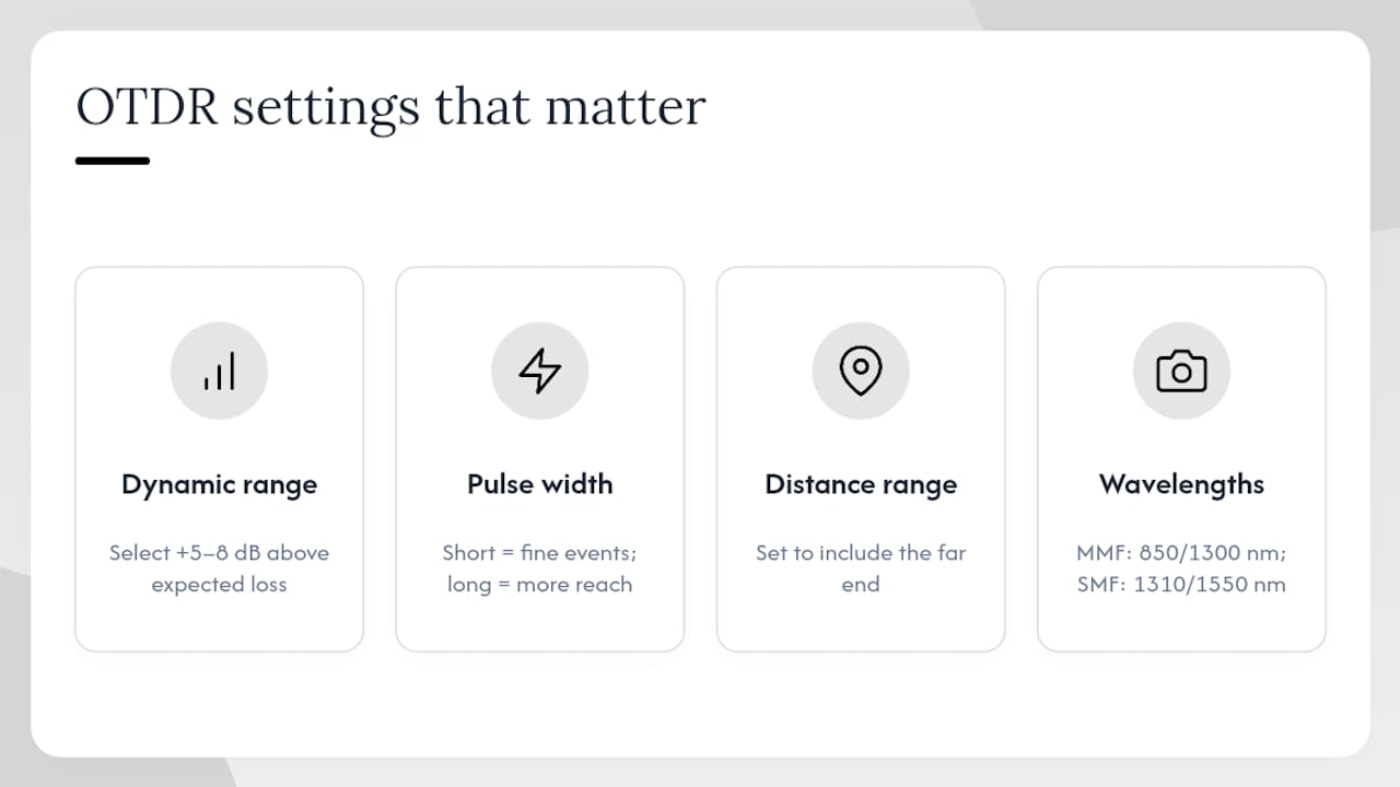
Dynamic range determines how much loss the instrument can see through before the signal disappears into noise. The rule of thumb, backed by EXFO’s OTDR guidance, is to select an OTDR with 5 to 8 dB more dynamic range than the expected total link loss. Undershoot that margin and you’ll get a clean trace for the first half of the run, then noise for the rest.
Pulse width is the classic trade-off. Longer pulses push more light down the fiber, extending reach and improving dynamic range, but they widen the dead zone around every event, the blind spot where the instrument can’t resolve a second event close behind the first. Short pulses do the opposite: tighter resolution near connectors and patch panels, less overall reach. This distinction splits into two related specs. The event dead zone governs how close two reflective events can sit before merging into one on the trace, while the attenuation dead zone governs how quickly the trace recovers enough to measure loss accurately after a reflection. In a dense data center rack with connectors every meter, an oversized event dead zone can hide an entire bad patch cord.
Wavelength selection depends on fiber type. Test multimode fiber at 850nm and 1300nm. Test single-mode fiber at 1310nm and 1550nm, since bend sensitivity and splice loss behave differently at each wavelength and a fault invisible at one may show clearly at the other.
Pro Tip: Run a short-pulse trace first to nail down event locations near patch panels, then run a long-pulse trace for overall reach. Keep both in the job file. Relying on a single acquisition setting is how technicians miss a marginal connector buried in a dead zone.
How Do You Set Up an OTDR Test Correctly?
A perfect instrument produces a useless trace if the setup is sloppy. Follow this sequence every time:
- Inspect and clean every connector before you plug in anything. A dirty end-face is the single most common cause of a trace that looks like a failed link when the fiber itself is fine.
- Attach a launch cord, typically 50 to 100 meters, between the OTDR and the link under test. This moves the instrument’s own front-panel dead zone off the connector you actually care about, so you can measure the first splice or patch accurately instead of losing it inside the OTDR’s blind spot.
- Attach a receive cord of similar length at the far end for the same reason, letting you see the last connector on the link instead of losing it in the end-of-fiber reflection.
- Set acquisition parameters: choose a distance range slightly longer than the known link length, select pulse width based on expected event spacing, and set averaging time long enough to smooth out noise. Auto mode works well for a quick check, but manual settings give more control on critical links.
- Test in both directions. Run the trace from Point A to Point B, then reverse the setup and test B to A.
That last step isn’t optional busywork. Bidirectional testing exists because loss at a splice can measure differently depending on which direction light travels through it, especially when two fiber segments have slightly mismatched core geometries. Averaging the two directional results gives you the connection’s true loss instead of a number skewed by backscatter mismatch.
Pro Tip: If you only have time to test one direction on a rush job, say so explicitly in the report. A one-directional trace on a fiber with any splice history is a guess dressed up as data.
How Do You Interpret Common Trace Events?
Once you’ve got a clean bidirectional trace, the real work starts: matching what you see to what’s actually wrong on the line.
Reflective spikes almost always point to connectors or unterminated end-faces. A tall, narrow spike with a clean recovery afterward usually means a mechanical connection with some reflectance but acceptable loss. A spike paired with a big loss step right after it is a strong sign of a dirty or damaged end-face; re-inspect and clean before assuming the connector itself has failed.
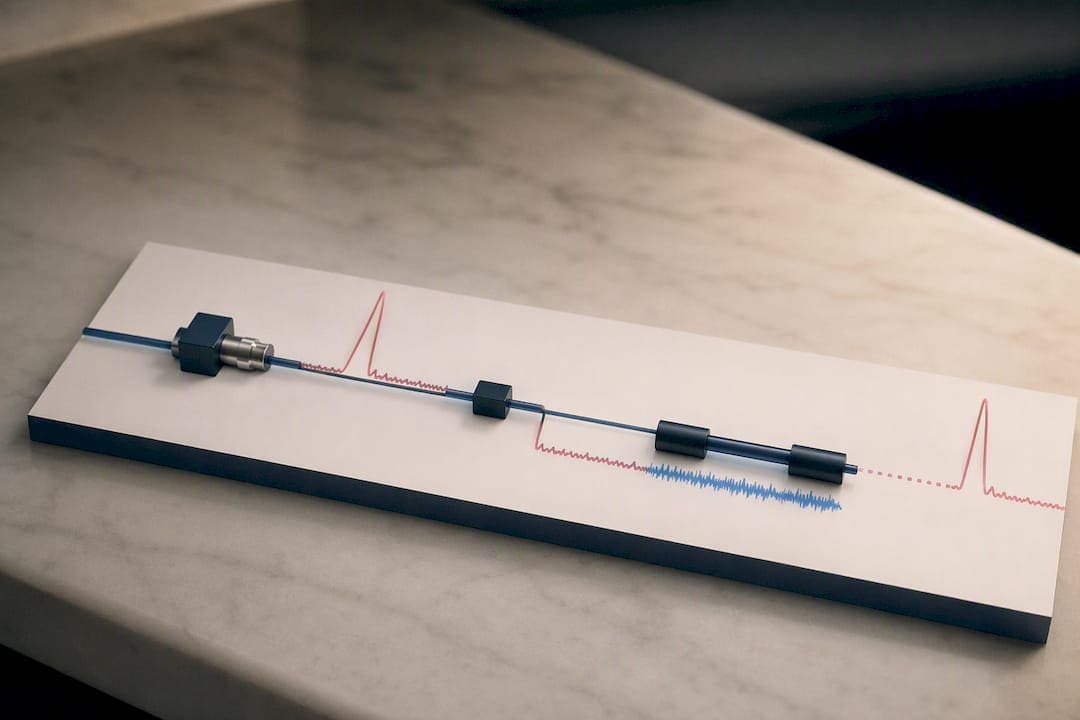
Non-reflective steps signal splice quality issues or macrobends, since there’s loss but no glass-to-air interface to reflect light. If the step shows up at a known splice location, the fusion splice likely needs redoing. If it shows up mid-span with no splice on record, check the routing for a tight bend radius, often behind a rack or where cable was stapled during a rushed install.
Gainers, where the trace appears to show a loss that doubles back into a power gain, are not real gains. They’re a signature of two fiber segments with different backscatter coefficients meeting at a splice. The correct read is always the bidirectional average, never the single-direction number.
Ghosts are the trickiest artifact. They appear as an event signature beyond the physical end of the fiber, or occasionally in the middle of a trace, caused by light reflecting between two high-reflectance points multiple times before returning to the receiver. If an “event” doesn’t correspond to any known splice, patch panel, or termination on the as-built drawing, treat it as a ghost until proven otherwise. Confirm by changing pulse width. Real events stay put; ghosts often shift or disappear.
A dynamic range window of 30 to 50 dB on a typical OTDR sounds generous, but a single dirty connector can cost 0.75 dB or more, and a handful of them stacked across a long backbone run eats that margin fast.
What’s the Right Troubleshooting Workflow?
A trace showing a fault doesn’t mean the job is done, it means the diagnostic phase is done. What happens next follows a predictable sequence.
- Inspect and clean the suspect connector or bulkhead first. This single step resolves a surprising share of “failed” links before any tool touches the fiber again.
- Retest with adjusted settings. Switch to a shorter pulse if the fault sits near another event, or extend averaging time if the trace looked noisy.
- Verify bidirectionally. A fault that shows up in one direction but not the other points toward a backscatter mismatch rather than an actual break.
- Localize precisely with a visual fault locator or fiberscope once the OTDR narrows the fault to a general area, especially useful for finding a break behind a wall or above a ceiling grid.
- Repair and retest the full link end to end, not just the section you fixed, since a new splice or connector introduces its own small loss.
Once the OTDR trace comes back clean, that’s the signal to move to final acceptance testing. OTDR characterization belongs before OLTS certification in the project sequence, so any bad splice or connector gets corrected during install rather than discovered after the network goes live and someone’s blaming a switch that was never the problem.
Documentation closes the loop. Every acceptance package should include the saved trace files, the settings used (pulse width, wavelength, averaging time), and the launch and receive cord lengths. Without that context, a trace six months from now is just a squiggly line nobody can act on.
Field Checklist for OTDR Testing on Commercial Jobs
Every OTDR test on a New York City commercial job starts the same way, regardless of building age or fiber count.
- Confirm expected link length and topology against the as-built drawing before powering on the instrument.
- Inspect and clean every connector, launch cord, and receive cord end-face.
- Set wavelengths to match fiber type, and always run both wavelengths on single-mode backbone runs.
- Check launch cord length matches the front-panel dead zone spec for the OTDR in use.
Older buildings with mixed-vintage risers throw the most curveballs. It’s common to find a patch panel from a previous tenant fit-out still live in the path, adding an unexpected event nobody flagged on the drawing. Running the trace before assuming the topology matches the drawing catches that every time.
Pro Tip: Include a printed or PDF trace image in every client handoff, not just a pass/fail summary line. A visual record cuts callback disputes dramatically because the client can see exactly where and why a connection measured the way it did.
The report itself should include acquisition settings, both directional traces, and a plain-language note on any event that came close to the loss budget but still passed.
Why We Run OTDR on Every Enterprise Fiber Install
Cables and Chips runs OTDR characterization on backbone and riser fiber before we ever touch an OLTS. Skipping that step and jumping straight to certification has, in more than one building, meant a marginal splice sails through as a pass, then fails intermittently under load once the network goes live. Pairing both test types into one report gives the client a document that shows the fiber the day it was accepted, which cuts down on finger-pointing during future service calls.
— Ken
Get OTDR and OLTS Testing Done Right the First Time
Cables and Chips is the alternative to hiring a separate testing vendor after your fiber goes in. We handle installation, termination, and a full OTDR-plus-OLTS test sequence as one job, so there’s no gap between who ran the cable and who certified it.

Every commercial and secure facility we work in across New York City gets the same deliverable: bidirectional OTDR traces, OLTS insertion-loss results, and documentation built for acceptance and future troubleshooting, not just a one-line pass/fail sheet. If a splice or connector doesn’t meet spec, we correct it and retest before the job closes, not after your team discovers it during a network outage. If you’re planning a fiber backbone install, an upgrade, or need a proper test-and-certify pass on existing infrastructure, visit our fiber installation and testing page to get a quote and schedule a site visit.
Sources
For deeper technical detail beyond field practice, consult Fluke Networks’ OTDR guide, the FOA’s QuickStart guide to OTDR testing, and device-specific application notes for exact specs on your instrument, since dead zones and dynamic range vary by model.
- OTDR testing fundamentals — Yokogawa / TMI application note
- OTDR fundamentals — EXFO application note
FAQ
What Does an OTDR Test Actually Measure?
An OTDR measures total link loss, distance to each event, fiber attenuation in dB/km, individual splice or connector loss, and reflectance at connection points, using backscatter and reflection patterns along the fiber.
How Much Does an OTDR Cost?
Professional OTDRs range from roughly $2,000 for basic handheld units to $20,000 or more for advanced, quad-wavelength models, with price tracking dynamic range and dead-zone performance.
What Is an OTDR Tester Used For?
An OTDR is used for locating faults, characterizing splice and connector loss, and Tier 2 troubleshooting after installation, while final insertion-loss certification still requires an OLTS.
How Do I Set Up an OTDR Test Properly?
Clean and inspect every connector, attach launch and receive cords to move dead zones off the link under test, set distance range and pulse width to match the expected link, and test in both directions before averaging the results.
Should I Test at One Wavelength or Multiple?
Test multimode fiber at 850nm and 1300nm and single-mode fiber at 1310nm and 1550nm, since certain faults show up more clearly at one wavelength than the other.