
Optical Loss Testing for NYC Installers: OLTS, OTDR, 3 dB Rule
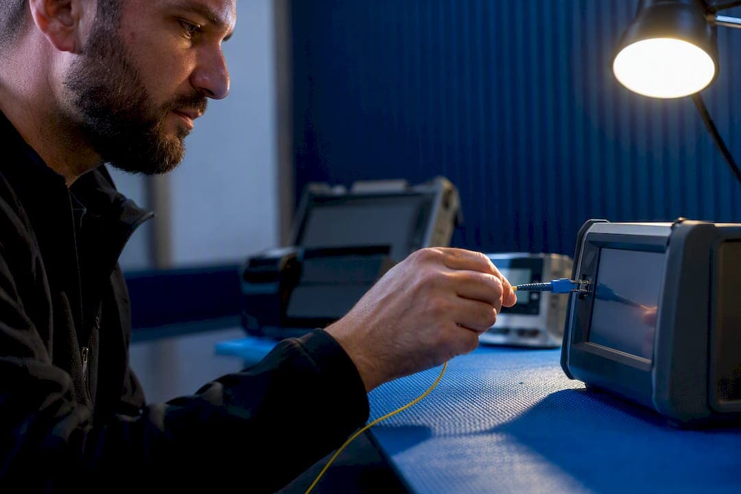
Use an OLTS (insertion-loss test) to certify total link loss, and use an OTDR to locate faults and document the span. An OLTS measurement is the industry-preferred method for Tier 1 certification because it directly measures how much light actually reaches the far end, the same way live network equipment will see it. OTDR testing is Tier 2 work: diagnostic, not a substitute. Every pass/fail decision should reference your link budget minus roughly 3 dB of repair margin.
TL;DR:
- Use an OLTS with a 1-cord reference method to accurately measure insertion loss and ensure it stays below the link budget minus a 3 dB repair margin for certification.
- Confirm connectors are clean and well-conditioned to prevent contamination from causing false failures during testing.
- Employ an OTDR primarily for locating faults and verifying physical span attributes, acknowledging that its loss readings are typically lower than OLTS measurements.
- Document all testing parameters, reference methods, and conditions thoroughly to ensure repeatability and reliable long-term comparison.
- Always verify the reference method used if loss numbers seem higher than expected, as different methods can introduce significant variations in reported loss.
What Optical Loss Testing Actually Measures
Optical loss testing answers one question: how much of the light launched into a fiber link actually survives the trip to the far end? That number is called insertion loss, and it’s expressed in decibels (dB). Every connector, splice, and meter of fiber eats a little bit of signal. Stack enough of them together and a link that looked fine on paper starts dropping packets or refusing to link up at all.
Insertion loss only tells half the story. The other half is the link budget, which is the maximum loss your transceivers can tolerate before the signal drops below the receiver’s sensitivity threshold. A 10G optic might tolerate 3 dB of loss on a multimode run; a long-haul single-mode DWDM system might budget for 20 dB or more. Your measured insertion loss has to come in under that budget, with room left over.
That extra room is your headroom, or repair margin. It’s not optional padding. Fiber networks degrade over time from bend stress, connector wear, and the inevitable “someone spliced in a new run” that happens six months after installation. A link tested right at the edge of its budget today will fail in a year. Industry guidance recommends banking around 3 dB of margin against future repairs and degradation.
By the end of a proper optical loss test, you should be walking away with:
- A pass/fail determination for each fiber, referenced against a calculated link budget
- Measured insertion loss in dB at each required wavelength
- Documentation identifying the reference method, equipment, and technician
- A record you (or the next technician) can compare against on a future retest
Skip any one of these and you haven’t finished the job. You’ve just made a light turn on.
How OLTS Testing Measures Insertion Loss
An optical loss test set, or OLTS, pairs a calibrated light source with a power meter. The source injects light at a known power and wavelength into one end of the fiber; the meter reads what actually arrives at the other end. Subtract the two numbers, correct for the reference, and you have insertion loss in dB. This setup approximates how real transceivers transmit and receive light, which is exactly why it’s the standard for Tier 1 certification instead of an OTDR.
Before any of that math means anything, you need a reference. The reference process establishes your 0 dB baseline, and the method you choose changes both your measured result and how much you can trust it.
- 1-cord reference (Method B). Zero the source and meter using a single reference cable connected directly between them, then insert the link under test. This includes both connectors at the link’s near and far ends in the measurement, which is why Tier 1 testing generally favors it.
- 2-cord reference (Method A). Use two reference cables joined at a mated pair to set the zero, then swap in the link under test. This excludes one connector interface from the reading, typically producing a lower loss number.
- 3-cord reference (Method C). Use three cables and two mated pairs to establish reference, then substitute the middle cable with the link under test. This method excludes both end connectors from the measurement entirely.
Each additional reference cord you remove from the equation shaves connector loss out of the final number, and that’s precisely the trap. A 3-cord reference will often read the lowest loss and look the most flattering on a report, but it also doesn’t reflect what the installed link, with its actual end connectors, will hand off to network equipment. That’s why Tier 1 certification favors the 1-cord method: it counts the connectors your switches and transceivers will actually plug into.
Pro Tip: If a client or building owner asks why your loss numbers run higher than a “quick check” someone else did, ask what reference method they used. A 2-cord or 3-cord reference on the same link can shave a full decibel or more off the reported number without the fiber itself performing any differently.
What an OTDR Actually Shows You
An optical time-domain reflectometer sends a laser pulse down the fiber and measures the light that bounces back through Rayleigh backscatter and Fresnel reflection. By timing how long it takes light to return from each event, the OTDR builds a map of the fiber’s length, marking every splice, connector, and bend along the way. It’s a diagnostic instrument, not a certification instrument, and confusing the two is one of the most common mistakes technicians make on-site.
Where an OTDR earns its place in your toolkit:
- Pinpointing the physical location of a bad splice, damaged connector, or macrobend, often within a few meters
- Showing the loss contributed by each individual event, not just the sum
- Measuring the physical length of a span, useful for verifying as-built documentation
- Revealing whether a cable was stressed or kinked during pulling, something an OLTS number alone won’t tell you
Where it falls short: an OTDR calculates loss from backscatter math, not direct transmission, and it doesn’t reliably capture the far-end connector unless you attach a receive cable past the link. That’s also why OTDR readings tend to run lower than OLTS numbers on the same fiber. The instrument is directional, too. A splice or connector can measure differently depending on which end you test from, which is why careful technicians run bi-directional traces on critical spans.
Pulse width matters as well. A short pulse gives you tighter event resolution, useful for finding closely spaced connectors near the test end, but sacrifices dynamic range, meaning you may lose visibility on a long trunk. A longer pulse reaches farther but blurs events that sit close together. There’s no universal setting. You pick pulse width based on span length and what you’re hunting for.
A Tiered Workflow: Combining OLTS and OTDR in the Field
Certifying a link isn’t a single test. It’s a sequence, and skipping steps is how technicians end up chasing phantom failures that were really just dirty connectors.
- Inspect and clean every connector end-face before you connect anything, using a fiber scope and an appropriate cleaning kit.
- Set your OLTS reference using the 1-cord method for Tier 1 work, confirming a stable 0 dB baseline at each required wavelength.
- Run the insertion-loss test through the link, testing both directions if the link’s application or your contract requires it.
- Compare the result against your calculated link budget minus repair margin to determine pass, marginal, or fail.
- If the link fails or reads marginal, or if it’s a long trunk requiring full documentation, run an OTDR trace to locate the specific event causing excess loss.
- Repair or re-terminate the identified fault, then retest with the OLTS to confirm the fix actually resolved the loss.
Single-ended OTDR testing with a launch cable is usually enough for routine documentation on short, straightforward runs. Long trunks, high fiber counts, or links where the far-end connector quality is a real risk warrant bi-directional OTDR testing from both ends, then averaging the two traces to cancel out directional bias.
When your OLTS and OTDR numbers don’t match, and they often won’t, trust the OLTS for the total loss figure and use the OTDR to explain where that loss is distributed. The two instruments answer different questions; they were never going to agree on a single number.
Reference Methods, Modal Control, and Measurement Uncertainty
The reference method you choose doesn’t just shift the measured number. It changes how much you can trust that number. Practical field comparisons on the same installed link illustrate this clearly: a 1-cord reference read the highest loss but with the tightest uncertainty band, while methods that excluded end connectors read lower but with wider variability.
That pattern holds in documented field comparisons: the method that includes more real-world connector interfaces produces a higher, but more repeatable, number. The methods that strip connectors out of the reference look cleaner on paper and are noticeably less consistent between test runs.
Multimode fiber adds a second wrinkle: modal power distribution. Multimode light travels in multiple modes simultaneously, and how those modes are distributed across the fiber’s core dramatically affects your loss reading. An overfilled launch, common with LED sources or poorly conditioned laser sources, pushes light into higher-order modes that lose more easily at splices and connectors. That produces pessimistic, non-repeatable results that don’t reflect how the link performs under real equipment.
The fix is modal conditioning: use a mandrel wrap on your launch cable, or a proper mode-conditioning launch cable rated for the fiber size you’re testing, to strip out higher-order modes and produce a steady-state modal fill before the light hits your reference connection. Without it, two technicians testing the same multimode link on the same day can get meaningfully different numbers, and neither one is technically wrong.
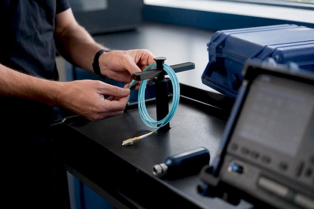
Pro Tip: Treat your reference jumpers like the precision test assets they are, not disposable patch cords. A cord that’s been dropped, stepped on, or connected a few hundred times without inspection will quietly inflate every measurement you take with it. Verify reference cords periodically, and never grab a “spare” patch cable off the rack to set your zero.
Three habits keep uncertainty in check regardless of method: inspect the reference cord’s end-face before every use, verify your adapters match the connector type you’re testing, and re-check your reference periodically throughout a long job, not just once at the start of the day.
Equipment Checklist and Setup Steps for Accurate Testing
Getting a trustworthy number starts before you touch a single connector. Your equipment and your setup routine matter as much as the fiber itself.
Bring the following to every job:
- OLTS: a calibrated light source and matching power meter, rated for the wavelengths you’re testing
- Launch and receive reference cables matched to the connector type on-site, with known good end-faces
- An OTDR appropriate for the span length and fiber type (single-mode or multimode)
- A fiber inspection scope, ideally one that can capture images for documentation
- A cleaning kit: dry cleaning cassettes, isopropyl wipes, and compressed air, kept sealed until use
- Adapters matched precisely to connector types (LC, SC, ST, MPO) with no forced fits
Before you test anything, warm up the source and meter per the manufacturer’s specification, typically a few minutes, so the readings stabilize. Then clean every connector you’re about to mate, inspect it under the scope, and only then set your 0 dB reference. Select wavelengths that match the application: single-mode links generally get tested at 1310 nm and 1550 nm, while multimode links get tested at 850 nm and 1300 nm. Testing at only one wavelength when the link will carry traffic at both is a common shortcut that leaves you blind to wavelength-dependent problems like a marginal splice that behaves differently at each wavelength.
Adapter mismatches cause more failed tests than actual bad fiber. Forcing an SC reference cord into an LC adapter, or using a worn adapter sleeve, introduces loss and back reflection that has nothing to do with the installed cable plant. Keep your adapters in good condition and dedicated to specific connector types, and never force a connection that doesn’t seat cleanly.
Field Best Practices That Prevent False Failures
Most “bad fiber” isn’t bad fiber. It’s a dirty end-face, and it’s the single most preventable source of a failed test.
- Inspect before every connection, using a fiber scope, not a visual check with the naked eye. Contamination that’s invisible to your eye will still scatter enough light to blow past your loss budget.
- Clean with a dry method first (a cleaning cassette or click-clean tool), reserving wet cleaning with isopropyl for stubborn contamination, followed by a dry finish.
- Log every test with enough detail that someone else could reproduce it: operator name, date, equipment model and serial number, reference method used, wavelengths tested, and the numeric results for each fiber.
- Store reference cords capped and coiled, never loose in a toolbox where connectors rub against hardware.
Industry guidance points to three recurring culprits behind inconsistent field results: technicians substituting an OTDR trace for a required OLTS certification, reference jumpers that have degraded from repeated use without inspection, and multimode tests run without proper modal control. Every one of those is a process failure, not an equipment failure, and every one is preventable with a five-minute inspection habit.
Documentation deserves the same rigor as the physical test. A certification report missing the reference method or wavelength used is functionally useless six months later when someone needs to compare a retest against the original baseline. Write it down every time, not just when you remember.
Standards, Link Budgets, and Acceptance Criteria
TIA-568.3-E is the standard that defines the two-tier certification structure most commercial fiber work follows: Tier 1 covers loss, length, and polarity using an OLTS, while Tier 2 adds OTDR testing for documentation and diagnostics on more critical or higher-count installations. The same revision folded in TIA-526-28 for MPO attenuation measurement, reflecting how common multi-fiber push-on connectors have become in data center and backbone links. If your work involves single-mode cable plant specifically, ANSI/TIA/EIA 526-7 governs attenuation and optical return loss measurement practices for that fiber type. The Fiber Optic Association’s FOA-1 standard supplies the detailed procedural guidance behind the Tier 1 test itself.
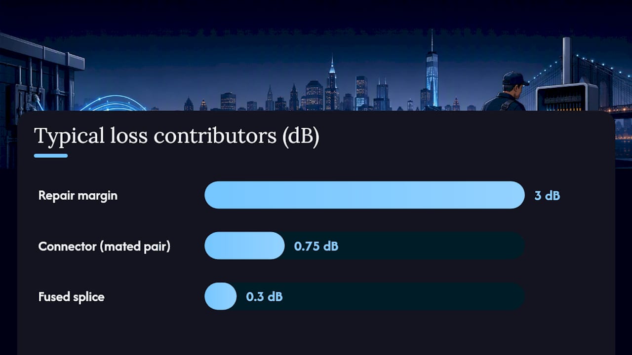
Calculating a link budget starts with your transceiver specifications: transmit power minus receiver sensitivity gives you total available loss. Subtract the loss allocated to connectors (typically 0.75 dB per mated pair) and splices (0.3 dB or less per fused splice) across the link’s length, then subtract fiber attenuation per kilometer at your test wavelength. What’s left, after subtracting roughly 3 dB for repair margin, is your acceptable measured loss ceiling.
A certification report that meets standards expectations includes:
- Fiber identification and length for each link tested
- Reference method, wavelengths, and equipment used, including serial numbers
- Measured insertion loss versus calculated budget, with a clear pass/fail
- OTDR traces where Tier 2 testing was performed or required
Troubleshooting a Failed or Marginal Optical Loss Test Result
A failed test isn’t the end of the job. It’s the start of a short, specific process, and jumping straight to “replace the cable” wastes time and money on links that just need a clean.
- Re-inspect every connector under a fiber scope, including your reference cords, since a contaminated reference will fail a link that’s actually fine.
- Swap your reference cords for a known-good set and retest before assuming the installed link is the problem.
- Clean any end-face showing contamination and retest immediately with the OLTS.
- If loss still exceeds budget, run an OTDR trace to locate the specific event responsible.
- Identify the event type: a sharp, isolated spike typically indicates a connector or mechanical splice, a gradual step usually points to a fusion splice, and a slow-rising loss over distance suggests a macrobend or cable stress point.
- Repair the identified fault (re-terminate, re-splice, or address the physical stress), then retest with the OLTS to confirm.
As a rough guide, a single connector reading above 0.75 dB or a fusion splice above 0.3 dB warrants a closer look, though your specific link budget is the real deciding factor, not a universal threshold. Once a link passes with documented margin intact, log the final results and hand the report back for acceptance. Don’t let a marginal pass slide through undocumented. The next technician troubleshooting that link in two years will need the baseline you’re creating today.
What Twenty Years of Certification Reports Teach You About Loss
Cables and Chips has spent more than 40 years wiring commercial buildings across New York City, and fiber links get certified far more carefully than they get installed carelessly, the mistakes repeat themselves. Reference method confusion tops the list. A technician who sets a 3-cord reference because it’s faster and reports a passing number has technically completed a test, but not the test the building owner actually needed.
Three habits carry weight on every job: always verify the reference method is 1-cord before signing off on Tier 1 documentation, label and store reference cords as dedicated test assets rather than spare patch cables, and require OTDR documentation on any trunk run longer than roughly 300 meters or on any link feeding critical infrastructure like a server room or security system backbone.
Technicians and IT teams looking for the full contractor-grade procedure, including documentation templates, can reference the Cable Plant Testing for IT Professionals guide for the complete field protocol Cables and Chips applies on commercial installations.
Cables and Chips Handles Optical Loss Testing on Every Fiber Install We Run
Cables and Chips is the contractor New York City building owners and IT departments call when a fiber backbone needs to actually pass Tier 1 certification, not just look plugged in. Every fiber run we install or service gets tested with a calibrated OLTS using the 1-cord reference method, with OTDR documentation added on longer trunks and critical infrastructure runs, so you get a certification report that holds up under real network load, not just a quick continuity check.

That matters most for offices, secure facilities, and server rooms where a marginal fiber link means intermittent outages nobody can diagnose after the installer leaves. If your building is planning new fiber optic infrastructure or needs an existing backbone tested and certified before a tenant fit-out or equipment upgrade, our team handles the full scope: design, termination, testing, and documentation, all backed by more than 40 years of low-voltage work across Manhattan’s commercial buildings. Reach out to schedule a fiber testing or installation assessment for your space, and get a certification report you can actually stand behind.
— Ken
FAQ
How Much Loss Is Acceptable in a Fiber Link?
Acceptable loss depends on your specific link budget, calculated from your transceiver’s transmit power and receiver sensitivity minus connector, splice, and fiber attenuation. Industry practice recommends reserving about 3 dB of repair margin below that budget rather than testing to the exact ceiling.
What Does an OLTS Test Actually Measure?
An OLTS measures insertion loss, the total light lost between a calibrated source and a power meter across the full link. It’s the preferred method for Tier 1 certification because it reflects how real network transceivers transmit and receive light.
What Is OTDR Testing and What Does It Show?
An OTDR sends a laser pulse down the fiber and reads backscattered light to build a map of splices, connectors, and bends along the span. It’s a Tier 2 diagnostic tool for locating and sizing individual events, not a replacement for OLTS certification.
What Commonly Causes Low Optical Return Loss?
Low optical return loss (meaning excessive reflection) most often traces back to a poor connector end-face finish, contamination, or an air gap at a mated connection. Dirty or damaged connectors are consistently cited as one of the leading causes of inconsistent test results in the field.
Should I Trust the OTDR Number or the OLTS Number When They Disagree?
Trust the OLTS number for total link loss and certification purposes, since it directly measures transmission the way network equipment will experience it. Use the OTDR to explain where that loss is distributed along the span, since the two instruments measure loss through different methods and rarely produce identical figures.