
Open Ceiling Office Cable Management: 2026 Guide
TL;DR:
- Proper cable management involves compliant support spacing and anchoring to building structures in open ceilings. J-hooks suit retrofit projects with fewer cables, while cable trays are better for high-density, new construction environments. Maintaining clearances, documentation, and planning for future growth is essential to prevent costs and violations.
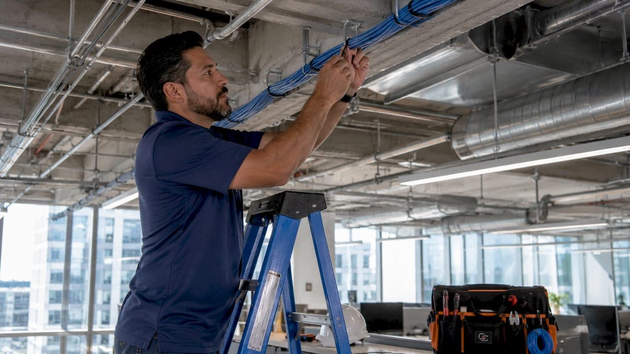
Effective cable management in open ceiling offices is defined as the organized routing, support, and documentation of overhead cable runs using compliant hardware and spacing standards. The industry terms for this discipline are overhead cable management and structured cabling support, and both apply directly to how you handle cable management in an open ceiling office environment. BICSI and NEC 800.24 set the foundational rules: maximum 5-foot spacing on horizontal cable supports, with tighter 3-foot spacing at corners and drops. Getting these fundamentals right from the start prevents sagging, code violations, and costly rework during tenant fit-outs.
What are the key standards and spacing requirements for cable supports in open ceilings?
Cable support spacing is the single most cited compliance failure in open ceiling office installations. BICSI and NEC 800.24 require horizontal supports no greater than 5 feet on center. At corners, bends, and vertical drops, that spacing tightens to 3 feet to prevent cable stress and sag.
Why spacing matters beyond compliance
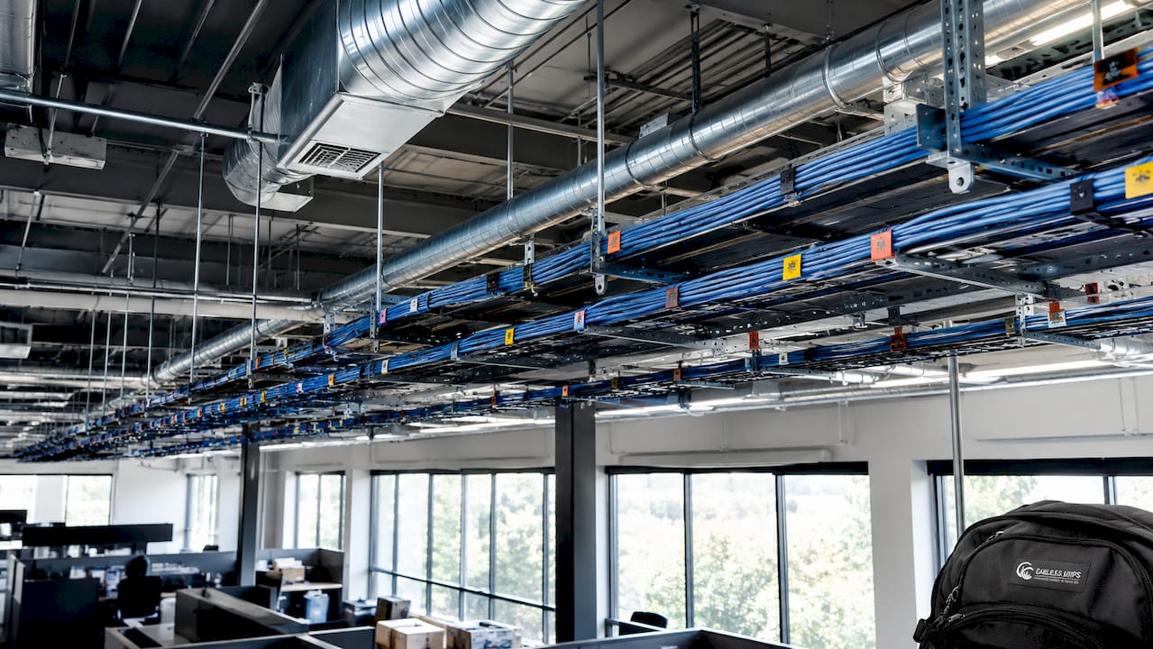
Improper spacing does more than fail an inspection. Cables that sag between widely spaced supports experience mechanical stress at the support points, which degrades the cable jacket over time. In CAT6A runs, jacket damage can affect the cable’s ability to maintain the tight pair geometry needed for 10-Gigabit performance. The physics are simple: more support points mean less cable weight per hook, which means less deformation.
Bundle size also changes the spacing equation. A single CAT6 cable weighs almost nothing. A bundle of 40 cables running 100 feet accumulates real weight. Larger bundles require closer spacing to prevent the entire run from pulling down at midpoints. The general rule is to reduce spacing incrementally as bundle diameter increases, even if the 5-foot maximum still technically applies.
NEC mounting rules: structure, not ceiling grid
NEC forbids attaching cable supports to suspended ceiling grids. Cables must anchor to the building structure itself, using threaded rods, beam clamps, or dedicated support wires tied to structural members. This is the most commonly failed item during NEC inspections. A ceiling grid is designed to hold lightweight ceiling tiles, not cable bundles under tension.
NEC inspectors regularly fail jobs where J-hooks are clipped to T-bar ceiling grid rails. The fix after the fact is expensive: you must remove the hooks, install proper structural anchors, and re-route the cables. Planning for structural attachment from the start eliminates that risk entirely.
Pro Tip: Before drilling or clamping anything overhead, confirm with your building engineer which structural members are accessible and rated for cable support loads. In older Manhattan office buildings, this step alone can save days of rework.
| Requirement | Standard | Specification |
|---|---|---|
| Max horizontal support spacing | BICSI / NEC 800.24 | 5 feet on center |
| Spacing at corners and drops | BICSI | 3 feet on center |
| Cable support attachment point | NEC | Building structure only, not ceiling grid |
| Support within vertical drops | NEC | Within 24 inches of drop point |
How to choose between J-hooks and cable trays for managing cables overhead
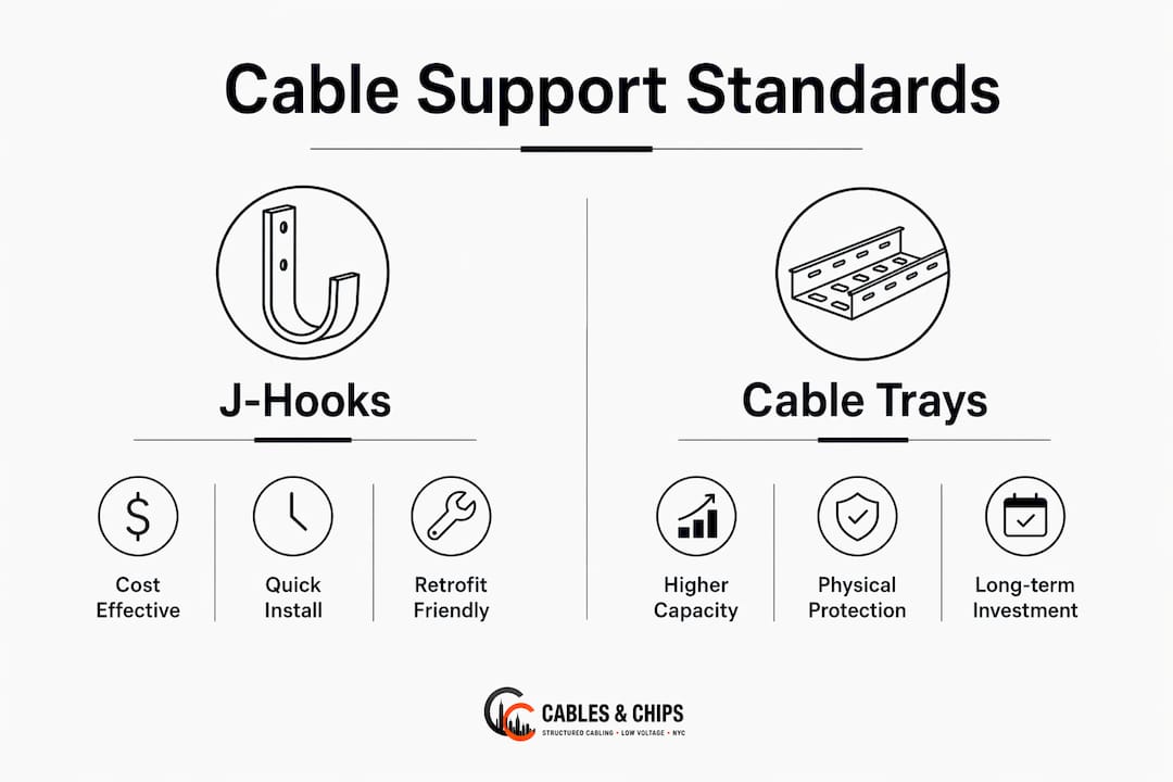
The choice between J-hooks and cable trays is the most consequential hardware decision in any open ceiling cable project. Industry standards recommend J-hooks for bundles under 50 cables and cable trays for high-density runs exceeding 50 cables. That threshold exists because cable trays provide physical enclosure and protection that J-hooks cannot offer at scale.
When J-hooks are the right call
J-hooks are the correct choice for retrofit projects in occupied buildings. They install faster, cost less, and require less ceiling clearance than cable trays. In a building where ceiling height is already tight and tenants are working below, J-hooks let you run new CAT6 or CAT6A without major disruption. For most standard office deployments with moderate cable counts, J-hooks deliver compliant results at a fraction of the cost.
Cable trays cost 4 to 10 times more than J-hooks and are significantly harder to modify after installation. That cost premium is justified when you need physical protection for cables, when bundle counts are high, or when you are building out a new construction project where tray installation can happen before walls and ceilings go in. Trying to retrofit a full cable tray system into an occupied office is a project that most facility coordinators regret starting.
When cable trays are worth the investment
Cable trays shine in new construction, data-intensive environments, and any space where cables need physical protection from foot traffic, equipment, or maintenance activity. A tray system also makes future adds and changes easier at scale. You can lay new cables into an open tray without disturbing existing runs, which matters in offices that reconfigure frequently.
Key factors to weigh when choosing between the two:
- Bundle size: Under 50 cables, J-hooks are sufficient. Over 50, cable trays provide better support and organization.
- Project type: Retrofit favors J-hooks. New construction favors cable trays.
- Ceiling clearance: Limited clearance favors J-hooks, which have a smaller vertical profile.
- Physical protection: Cables in high-traffic or industrial-adjacent areas need the enclosure a tray provides.
- Future growth: Trays accommodate more cables over time without requiring new hardware installations.
For open office cabling planning, the decision often comes down to a simple question: how many cables do you expect to run in the next five years, not just today?
What clearance and pathway organization practices are essential for cable trays in open ceiling offices?
Clearance rules for cable trays exist to protect both the cables and the technicians who maintain them. Professional guidelines require at least 6 inches of vertical clearance between stacked trays and at least 24 inches of horizontal gap between parallel trays. Those dimensions are not suggestions. They define the minimum space a technician needs to reach into a tray, pull a cable, or add a new run without damaging existing infrastructure.
Separating data cables from power wiring
Maintaining 6 to 12 inches of separation between data cabling and unshielded line-voltage power wiring is a NEC requirement and a practical necessity. Running CAT6 parallel to 120V or 208V power lines without adequate separation introduces electromagnetic interference (EMI) that degrades network performance. In severe cases, it causes intermittent connectivity failures that are extremely difficult to diagnose after the fact.
The separation rule applies to the entire cable run, not just at crossing points. Many facility coordinators correctly separate cables where they cross but then allow them to converge and run parallel for long distances. That parallel run is where EMI accumulates. The fix is to plan tray routes that keep data and power pathways physically separated from the start.
Pro Tip: When routing cable trays near HVAC ducts or sprinkler mains, coordinate with your mechanical contractor before installation. A commercial buildout planning guide can help you map conflicts before they become expensive ceiling clashes.
Coordinating cable pathways with mechanical systems
Planning cable tray routes alongside HVAC, sprinkler, and fire suppression systems is not optional. Ceiling voids in commercial offices are crowded spaces. A cable tray installed without coordination with mechanical drawings will eventually conflict with a duct, pipe, or sprinkler head, and one of them will have to move.
The correct sequence for pathway organization is:
- Obtain current mechanical, electrical, and plumbing drawings before laying out any cable routes.
- Mark proposed cable tray centerlines on a reflected ceiling plan and identify all conflicts.
- Resolve conflicts with the general contractor before any hardware is ordered or installed.
- Maintain the required 6-inch vertical and 24-inch horizontal clearances in the final layout.
- Document the approved pathway layout and keep it on file for future maintenance reference.
Failing to plan cable pathways with at least 25% spare capacity leads to cable congestion and eventual code violations during tenant renovations. That 25% buffer is not wasted space. It is the capacity that absorbs the next office expansion without requiring a full tray replacement.
How to properly install and maintain cable supports to avoid common pitfalls
Proper installation of cable supports follows a defined sequence. Skipping steps in that sequence creates problems that compound over time, from sagging runs to failed inspections to network outages caused by damaged cables. The following process applies to both J-hook and cable tray installations in open ceiling office environments.
Step-by-step installation process
-
Mark support locations before drilling. Pre-mark J-hook or tray hanger positions every 4 to 5 feet along the planned route, and every 3 feet at corners and drops. Marking first prevents misaligned hardware and ensures consistent spacing across the entire run.
-
Install structural anchors first. Attach threaded rods, beam clamps, or support wires to structural members only. Never attach to ceiling grid. Confirm anchor load ratings before hanging any cable weight.
-
Mount J-hooks or tray hangers at marked positions. Install all hardware before pulling any cable. Running cable through partially installed hardware damages jacket insulation and makes it harder to maintain consistent support spacing.
-
Pull cables and seat them properly in hooks or trays. Do not overfill J-hooks beyond 60% of their rated capacity. Leaving 40% headroom accommodates future cable additions without requiring new hardware.
-
Support cables within 24 inches of every vertical drop. This is a direct NEC requirement. Unsupported drops create tension at the transition point and can pull cables loose from terminations over time.
-
Photograph the completed installation before any ceiling tiles go back in. Documenting cable runs with photos before closing up the ceiling is the single most practical step for future inspections and fire marshal reviews. A visual record eliminates guesswork during maintenance.
Ongoing maintenance practices
Cable support systems require periodic inspection, not just a one-time installation check. Cables shift, bundles grow, and hardware loosens over time. A maintenance schedule should include:
- Annual visual inspection of all accessible support hardware for loosening, corrosion, or overloading.
- Bundle count audits at each J-hook to confirm no hook has exceeded its capacity rating.
- Documentation updates whenever new cables are added to an existing run.
- Plenum rating verification for any cables added in fire-return air plenum spaces, where plenum-rated CMP cable is required by NEC to prevent toxic smoke generation in a fire event.
For network closet organization that connects to your overhead runs, the same documentation discipline applies. A well-labeled, photographed overhead system that terminates in an unlabeled patch panel defeats the purpose of the overhead work.
Key Takeaways
Effective overhead cable management in open ceiling offices requires compliant support spacing, the right hardware for your cable density, and documented installations that hold up to inspection.
| Point | Details |
|---|---|
| Follow BICSI and NEC spacing rules | Space supports no more than 5 feet apart, with 3 feet at corners and drops. |
| Anchor to structure, not ceiling grid | NEC requires attachment to building structure; ceiling grid attachment fails inspection. |
| Match hardware to bundle size | Use J-hooks for under 50 cables and cable trays for larger, denser runs. |
| Maintain clearance and separation | Keep 6 inches vertical between trays and 6–12 inches between data and power cables. |
| Document and plan for growth | Photograph installations and size trays with 25% spare capacity for future expansion. |
What I’ve Learned from Watching Open Ceiling Jobs Go Wrong
After more than 40 years of low voltage work in New York City commercial offices, the pattern is consistent. The jobs that fail inspection or require expensive rework share one trait: the cable support plan was treated as an afterthought rather than a design decision.
The most common mistake I see is installers choosing J-hooks or cable trays based on what they have on the truck, not what the job actually requires. A retrofit in a 1970s Midtown office building with 8-foot ceiling clearance is not the same job as a new construction buildout in a modern Lower Manhattan tower. The hardware choice has to match the physical reality of the space.
The second mistake is ignoring the 25% spare capacity rule. Facility coordinators often push back on oversizing trays because it adds cost today. Three years later, when the office adds 20 workstations and the trays are already at capacity, that conversation looks very different. The cost of replacing undersized trays in an occupied office is always higher than the cost of sizing them correctly the first time.
The third mistake, and the one that causes the most pain, is skipping documentation. I have walked into buildings where no one could tell me where the cables ran, what they connected, or when they were installed. A set of photographs taken before ceiling tiles go back in costs almost nothing. The absence of those photographs can cost thousands in diagnostic labor during a network outage or fire marshal inspection.
The electrical upgrade planning side of a commercial renovation and the low voltage cabling side need to coordinate from day one. When they do not, you get ceiling clashes, EMI problems, and code violations that could have been avoided with a single coordination meeting.
— Ken
Cables and Chips: Professional Cable Support for NYC Offices
Cables and Chips installs compliant, documented overhead cable systems for commercial offices throughout New York City. Whether your project calls for J-hook runs in a retrofit space or full cable tray systems in a new buildout, the team at Cables and Chips applies BICSI and NEC standards on every job.

For office managers and facility coordinators who need overhead cabling done right the first time, the structured cabling components guide is a practical starting point for understanding what a compliant installation requires. Cables and Chips also offers CAT6 structured cabling installation across all five boroughs, with full testing, certification, and as-built documentation included. Contact Cables and Chips at 20 Vesey Street, Lower Manhattan, to schedule a site survey.
FAQ
What is the maximum spacing for cable supports in an open ceiling?
BICSI and NEC 800.24 require horizontal cable supports no more than 5 feet apart on center. At corners and vertical drops, spacing must tighten to 3 feet.
Can I attach J-hooks to a suspended ceiling grid?
No. NEC prohibits attaching cable supports to ceiling grids. All supports must anchor to the building structure using threaded rods, beam clamps, or dedicated support wires.
How far apart should data cables be from power wiring?
Data cables must maintain 6 to 12 inches of separation from unshielded line-voltage power wiring to prevent EMI and comply with NEC fire codes.
When should I use cable trays instead of J-hooks?
Cable trays are the correct choice when cable bundles exceed 50 cables, when physical protection is needed, or when the project is new construction. J-hooks are better suited for retrofit jobs with limited ceiling clearance and lower cable counts.
How much spare capacity should I plan for in a cable tray?
Size cable trays with at least 25% spare capacity beyond your current cable count. That buffer prevents congestion and code violations when the office expands or reconfigures.