
MTP vs MPO Cabling: What to Specify and Why It Matters
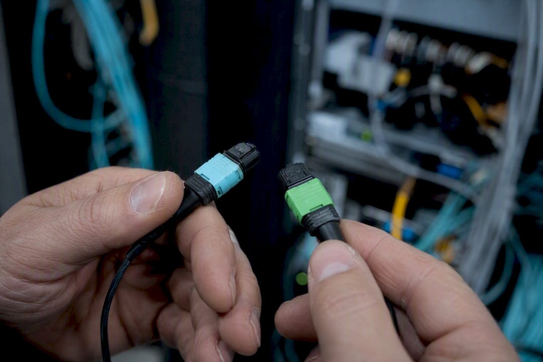
MTP is a high performance, field serviceable implementation of the MPO standard. Specify MTP or MTP Elite when you’re deploying 400G or 800G links, using direct-attach transceivers, or expecting frequent moves, adds, and changes. Generic MPO still works fine for budget 40G and 100G links where loss margins are forgiving. The three failures that sink most installs, regardless of connector brand, are pinning errors, polarity mismatches, and skipping proper MPO-native testing.
TL;DR:
- MTP connectors outperform MPO in high-speed applications due to their floating ferrule and tighter guide pin tolerances, especially under frequent reconnects.
- Proper testing involves MPO-native equipment that measures all fibers simultaneously and verifies polarity before link acceptance to prevent invisible faults.
- Specify the correct gender, polarity method, and low-loss grade explicitly in procurement to avoid damage or performance issues during installation.
- Handling and installation require careful inspection of end faces, avoiding stress on connectors, and adhering to bend radius and cable management best practices to prevent damage.
- Compatibility between brands is generally mechanical, but performance varies, making documentation and choosing the same vendor or grade critical for maintaining loss budgets.
What Are MPO and MTP Cabling, and How Do They Interoperate?
MPO stands for Multi-fiber Push On, an IEC and TIA-defined connector interface that carries anywhere from 8 to 72 fibers in a single ferrule. MTP is US Conec’s trademarked, engineered variant of that same connector, built with a floating ferrule, a removable housing, and tighter mechanical tolerances.
The two are mechanically intermateable, so an MTP connector plugs into a generic MPO port without issue. What differs is performance, durability, and field configurability. Vendors use the terms loosely, sometimes interchangeably, which is exactly why your spec sheet needs to say “MTP” or “MTP Elite” explicitly whenever low insertion loss is a requirement. Writing “MPO” alone leaves room for a supplier to ship the cheapest connector that technically fits the port.
Mechanical and Optical Differences That Actually Matter in the Field
The floating ferrule is the single biggest reason MTP outperforms generic MPO under real-world conditions. In a standard MPO connector, the ferrule is rigidly fixed to the housing, so any twist or pull on the cable transfers stress directly to the fiber-to-fiber contact point. MTP’s ferrule floats independently, decoupling that contact point from housing rotation and cable strain. That matters most on links that plug straight into a transceiver or get reseated repeatedly during moves and adds.
Guide pins tell the rest of the story. MTP connectors use elliptical guide pins manufactured to tighter tolerances than generic MPO, which cuts down on lateral misalignment during mating. The practical result shows up in your loss budget.
Typical insertion loss ranges look like this:
- Generic MPO: often in a range of typical insertion loss per mated pair
- Standard MTP: improved consistency, typically landing in the lower half of that range
- MTP Elite (low-loss): tighter typical loss and markedly higher repeatability, built for links with little margin to spare
Pro Tip: Mating-cycle durability isn’t just a spec sheet number. If your fabric sees frequent transceiver swaps or cassette reconfigurations, a connector rated for more mating cycles will save you truck rolls a year from now.
Fiber Counts, Network Speeds, and Breakout Architecture
Fiber count is a design decision, not an afterthought, and it should map directly to the optics you’re running.
- 8-fiber (8F): native to SR4 and SR8 parallel optics; the tightest match for 40G and 100G QSFP transceivers without wasted strands
- 12-fiber (12F): the workhorse for structured cabling flexibility, since it splits cleanly for LC breakout or pairs for trunk runs
- 16-fiber and 24-fiber: built for 400G and higher, and for ultra-high-density trunks feeding multiple switches from one pull
- Breakout cassettes (MPO-to-LC): the right call when a trunk needs to fan out to duplex LC ports at the rack
- Direct MPO trunks and jumpers: the right call when both ends terminate in parallel-optic equipment with no fan-out required
Fiber type and polish need equal attention. OM3 and OM4 multimode still dominate short parallel-optics runs, OM5 adds headroom for wideband applications, and OS2 single-mode takes over once distance or speed pushes past multimode’s reach. Polish matters too. UPC polish is standard for multimode MPO, while APC shows up on some single-mode variants to control back-reflection. A 24-fiber MTP/MPO to LC cassette is a common building block for exactly this kind of breakout, and choosing OM4 versus OM3 comes down to the speed and distance your switches actually need to reach.
What Are the Pinning and Polarity Rules for MPO/MTP?
Pinning is where installs go wrong fastest, because the mistake is invisible until you plug something in and it doesn’t work, or worse, it breaks.
- Know your gender defaults. Equipment ports are almost always pinned (male), so the mating cable end needs to be unpinned (female) to avoid pin damage.
- Pick a polarity method and stick to it. Type A runs straight through, Type B reverses fiber positions end to end, and Type C flips fiber pairs. Method B is the common default for new data center builds because it lets you use identical patch cords on both ends instead of stocking direction-specific cords.
- Order and label deliberately. Specify pinned or unpinned per connector end on every purchase order, and label assemblies at both ends with polarity type before they leave the staging area.
- Inspect before you mate. Check for bent or missing pins and confirm polarity markings match your documentation before the first connection, not after a failed link test.
Pro Tip: Pin crush from mating two pinned connectors together is not something you fix in the field. It’s a scrap-and-reorder problem, so incoming inspection at the loading dock is cheaper than any repair.
How Do You Test and Commission MPO/MTP Links?
Point-and-shoot single-fiber testers were never built for a 12 or 24-fiber ferrule, which is why MPO-native testers exist. Testers that measure every fiber in the connector simultaneously, rather than one strand at a time, cut commissioning time dramatically on high-density trunks and are the approach IEC TR 61282-15 guidance points toward for accurate per-fiber results on MPO-terminated links.
A commissioning sequence that holds up on real jobs:
- Inspect and clean every ferrule end face before the first mate, using a fiber inspection scope, not a visual guess
- Run per-fiber insertion-loss testing across the full connector, not a sample of strands
- Verify polarity fiber-by-fiber against the documented method (A, B, or C) before calling the link complete
- Choose OTDR tracing when distance or event location matters, and skip it for short, straightforward patch runs
- Generate and retain test documentation for every trunk, tied to a link ID
Link budgets for 400G and 800G parallel optics leave little room for surprises, so testing early in the design phase, not after cables are pulled, prevents expensive rework later. Cables and Chips’ own cable plant testing guidance covers the documentation formats most enterprise IT teams expect at handoff.
Procurement Checklist: What to Put in Your RFP or PO
Copy this into your next fiber procurement request and fill in the blanks per run.
- Connector designation: generic MPO or branded MTP, stated explicitly
- Low-loss requirement: standard grade or MTP Elite, by link type
- Gender per end: pinned or unpinned, specified for both connector ends
- Polarity method: Type A, B, or C, documented and labeled
- Fiber type and count: OM3, OM4, OM5, or OS2, in 8F, 12F, 16F, or 24F
- Polish type: UPC or APC
- Maximum insertion loss: stated in dB per mated pair, not left to the vendor’s discretion
- Test deliverables: MPO-capable test reports, per-fiber results, retained on file
Beyond the line items, settle your spare parts policy before installation day. Stock a mix of pinned and unpinned spares sized to your MAC volume, and require full labeling and as-built documentation as a deliverable, not an afterthought. Generic MPO is a reasonable choice for short 40G or 100G runs with healthy loss margin. Anything feeding 400G optics, high-MAC racks, or mission-critical fabrics should default to MTP Elite, and mixing Elite and standard connectors on the same link complicates the loss budget unless your design explicitly plans for it.
How Should You Install MPO/MTP Cabling to Avoid Damage?
Most physical damage to MPO and MTP assemblies happens in the first ten feet from the box, not years later in production. The ferrule end face is the most vulnerable point on the entire assembly, and a single scratch or contamination event there can push insertion loss past your budget before the link ever sees traffic.

Handle every connector by the housing, never the boot or the cable jacket, when seating it into a port. Pulling on the jacket to “help” a connector click into place is one of the fastest ways to stress the fiber at the ferrule interface, and with a floating ferrule design, that stress transfers differently than it would on a rigid MPO, which is exactly why MTP tolerates rougher handling better but still isn’t immune to it.
During cable pulls, never exceed the assembly’s rated pull tension or minimum bend radius, and always pull with a preterminated connector cap in place to protect the end face from dust and debris in the pathway. Coil excess slack in loose loops rather than tight bends at the cassette or panel, since a tight bend radius under load is a slow, silent way to degrade signal over months.
Before every mate, inspect the end face with a fiber scope rather than trusting a visual check with the naked eye. A contaminated ferrule mated blind can transfer debris to the port side, turning a five-minute cleaning job into a full connector swap. Keep dust caps on unused connectors at all times, including spares sitting in a drawer, because contamination doesn’t wait for installation day to start accumulating.
Finally, stage cassettes and trunks in a controlled area before the final pull. Preterminated assemblies tested and inspected on a bench, rather than in a half-finished IDF closet, catch damage while it’s still cheap to fix.
Environmental Factors and Cable Management for High-Density Racks
MPO and MTP trunks live and die by how well they’re managed inside the rack, not just how well they’re terminated. High-density environments compound every small mistake, because one poorly dressed trunk in a 96-port panel can block airflow, strain neighboring connectors, and make future MACs painful for everyone who touches that rack after you.

Bend radius discipline matters more with high fiber counts than with single-strand cabling, since a 24-fiber ribbon under a tight bend puts stress on every fiber inside it simultaneously. Use rack-mounted radius guides and vertical cable managers sized for the trunk diameter you’re actually running, not a generic manager pulled from stock.
Thermal load inside a dense fiber enclosure is a real consideration, particularly in telecom rooms without dedicated cooling. Fiber itself tolerates heat reasonably well, but the polymer jacketing and connector housings degrade faster under sustained high temperatures, and a poorly ventilated MDF closet packed with active equipment can shorten the service life of everything inside it.
Cassette-based systems help here, because they let you route trunk cables to a fixed location and handle patching changes at the LC side without ever touching the MPO connection again. That single design choice cuts down on repeated handling of the most sensitive part of the system.
Label everything at both ends, and document port assignments the day the trunk goes live, not weeks later from memory. In a facility with hundreds of MPO ports, an undocumented trunk is a liability the next time someone needs to trace a link during an outage at 2 a.m.
How Do You Troubleshoot MPO/MTP Connection Problems?
When an MPO link fails or underperforms, the fault almost always traces back to one of four causes: contamination, a polarity mismatch, physical damage, or a bad mating cycle.
Start with a visual inspection using a fiber scope on both ends of the suspect link. Contamination is the most common culprit by a wide margin, and it’s often invisible to the naked eye. A single dust particle or oil smudge on the ferrule end face can spike insertion loss well past an acceptable threshold.
If the end faces are clean, check polarity next. A link that passes insertion-loss testing but delivers no signal, or scrambled signal, is frequently a Type A versus Type B mismatch somewhere in the path, especially in a fabric with mixed patch cords from different vendors. Trace the polarity method documented for that link back through every cassette and jumper in the chain.
Physical damage shows up as inconsistent readings across fibers within the same connector. If fiber 1 tests clean but fiber 6 shows elevated loss, suspect a bent or crushed pin, a chip on the ferrule, or debris lodged in a single position rather than a system-wide issue.
Finally, rule out a bad mating cycle. Connectors nearing the end of their rated mating-cycle life lose alignment precision gradually, not all at once, so a connector that tested fine six months ago can drift out of spec after repeated reseating. If a link that was reliable suddenly degrades with no obvious physical cause, check how many times that connector has been mated and unmated.
Document every failure and its root cause. Patterns across a facility, like recurring contamination on one specific cassette type, point to a process problem worth fixing at the source.
Are MPO and MTP Connectors From Different Brands Compatible?
Mechanical intermateability is the baseline promise across the MPO and MTP ecosystem, and it generally holds. A connector from one manufacturer will physically mate with a port from another, because both conform to the same underlying IEC and TIA connector interface specifications.
Where interoperability gets shaky is performance consistency, not fit. Two connectors that both call themselves “MTP” from different manufacturers can carry noticeably different typical insertion loss, because “MTP” itself is a trademark tied to specific engineering choices like the floating ferrule, and not every vendor implements those choices identically. Mixing a low-loss Elite-grade connector on one end of a link with a standard-grade connector from a different brand on the other end means your loss budget is only as good as the weaker component.
Some MTP variants take interoperability further with field-configurable options. Certain MTP PRO-style connectors allow polarity or gender changes in the field through a removable housing, which reduces how many separately pinned and unpinned SKUs you need to stock for a multimode install. That flexibility is brand-specific, though, so don’t assume every MTP connector on a spec sheet supports field reconfiguration just because one product line does.
The safest procurement practice is naming a single connector standard, and ideally a single manufacturer, for any link where mixed-brand components could complicate the loss budget. When you can’t control the brand, at minimum document the insertion-loss grade of every component in the path so the weakest link isn’t a surprise during acceptance testing.
Cables and Chips’ Field Perspective on MPO/MTP Cabling
Most MPO problems trace back to decisions made before a single fiber gets pulled. Cables and Chips builds cassettes ahead of the site visit whenever the design allows it, because bench-tested assemblies fail less often than anything terminated in a half-finished closet under deadline pressure.
Incoming inspection is not optional on our jobs. Every MPO assembly gets scoped and checked for pin gender and polarity labeling before it goes anywhere near a rack, which catches vendor mistakes before they become install-day mistakes. We also carry spare pinned and unpinned stock on every fiber job, because a missing connector type on a Friday afternoon shouldn’t stall a handoff.
Every link gets validated with MPO-native test equipment, and clients leave with full per-fiber test documentation, not a verbal assurance that “it tested fine.”
— Ken
How Cables and Chips Handles MPO/MTP Design and Installation
If your build calls for 400G-ready trunks, pinned and unpinned assemblies specified correctly on the first order, and test documentation that holds up during an audit, that’s the work Cables and Chips does every week across commercial and secure facilities in New York City.

Our fiber optic scope covers design, preterminated cassette and trunk assemblies, MPO-native termination and testing, and complete as-built documentation handed over at closeout. A quote typically starts with a site survey to confirm fiber counts, distances, and polarity requirements, followed by a spare parts plan sized to your MAC volume so a missing connector never stalls a future change. Every link ships with full test reports, not a verbal sign-off. If you’re planning a fiber backbone upgrade or a high-density MDF buildout, get in touch through our fiber installation and testing services page to schedule a site survey and get a scoped quote.
Sources
Save the IEC TR 61282-15 testing guidance and TIA connector specifications before your next procurement cycle. Both govern how MPO-terminated links should be measured and accepted. Require MPO-capable test logs referencing these standards in every acceptance package, and cross-check vendor “MTP” claims against Corning’s technical documentation on floating-ferrule performance before committing to a supplier for high-speed links.
- Maximizing the advantages of the MTP® connector | Corning
- Multi-fiber push on connectors (MPO) | Fluke Networks
- How to Choose Between MTP and MPO? – CommMesh
- MPO/MTP Fiber Connector Guide for Data Center Cabling | ShopFiberOptic
FAQ
What is the difference between MTP and MPO cables?
MPO is the generic IEC and TIA connector standard; MTP is US Conec’s trademarked, performance-enhanced version with a floating ferrule and tighter tolerances that reduce insertion loss.
What is an MTP/MPO fiber connector?
It’s a multi-fiber connector that mates 8 to 24 or more fibers in a single ferrule, used mainly for parallel optics like 40G, 100G, and higher-speed transceivers in data centers.
Is MTP the same as MPO?
They’re mechanically intermateable but not identical. MTP is a branded MPO variant with mechanical refinements, while generic MPO refers to any connector meeting the base standard without those enhancements.
What is an MTP cable?
It’s a fiber assembly terminated with MTP connectors on one or both ends, typically used as a trunk cable or a jumper feeding an MPO-to-LC breakout cassette in structured cabling.
Should I specify pinned or unpinned MPO connectors?
Specify unpinned (female) connectors for cables mating into equipment, since most equipment ports come pinned (male) by default, and mating two pinned connectors together risks permanent pin damage.