
4 to 5 ft J Hook Spacing for Installers: TIA/BICSI Rules & Checklist
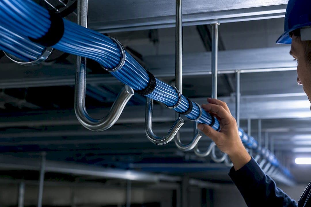
Space J-hooks 4 to 5 ft on center, and never exceed 1.5 m (5 ft) between non-continuous supports per ANSI/TIA‑569. Two caveats decide whether that spacing actually holds up: confirm the hook’s rated capacity against your bundle size, and tighten spacing wherever cables gather weight, fiber runs, corners, or drops. Measure and mark your layout before you pull cable, not after.
TL;DR:
- Supports placed every 4 to 5 feet are recommended for typical bundles, with closer supports needed near corners, drops, and transitions to prevent sagging.
- Exceeding 5 feet between supports violates ANSI/TIA‑569 standards and risks cable damage or performance issues, especially with heavier or fiber bundles.
- A standard 2-inch J-hook can hold about 50 to 60 Cat6 cables or 27 to 35 Cat6A cables, but capacity depends on cable type, jacket thickness, and bundling method.
- Mount supports to structural elements, not ceiling grids, and ensure supports are placed within 24 inches of drops or transitions to support cable integrity.
- Proper planning, documentation, and professional installation help avoid common mistakes like overloading supports or improper anchoring, which can cause costly rework after inspections.
What Is J-Hook Spacing, and What Do the Standards Require?
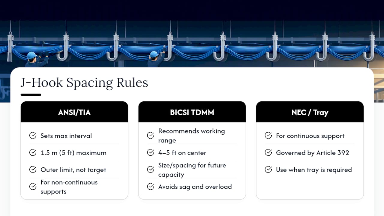
J-hook spacing is the distance between non-continuous cable supports along a horizontal run, and it’s governed by a hard ceiling rather than a suggestion. ANSI/TIA‑569 sets the maximum interval for J-hooks and bridle rings at 1.5 m, which is 5 ft. That’s the outer limit, not the target.
BICSI’s Telecommunications Distribution Methods Manual pushes installers toward a tighter working range of 4 to 5 ft on center for good reason. TDMM guidance calls for sizing and spacing supports based on anticipated future capacity, not just the cable count on day one, which keeps a rack full of Cat6A or fiber additions from turning into an overloaded support system down the line, according to BICSI’s TDMM.
The physics behind the rule matters as much as the number. Cable that sags between supports carries tensile stress it was never designed to handle, and that stress distorts the twisted-pair geometry inside the jacket. Distorted pairs mean crosstalk and return-loss problems that show up the moment you run a certification test, and a failed link means pulling new cable or adding supports after the fact, which Electricaltechnology lays out in detail.
One more distinction worth knowing before you spec a job: J-hooks are non-continuous supports, meant for runs where a full tray isn’t warranted. Once a pathway needs continuous support, you’re in cable tray territory, governed by NEC Article 392 rather than the J-hook spacing rules. Understanding how horizontal cabling pathways are planned helps clarify which method applies before the first hook goes in.
When Should You Tighten J-Hook Spacing Below 5 Ft?
The 5 ft maximum assumes a light, well-managed bundle. Add weight, fiber, or a direction change, and that number needs to come down.
Industry practice, echoed in BICSI-based field guidance, tightens the working rule to roughly 4 to 5 ft as a default, then shortens it further at specific pressure points:
- At a 90-degree turn, place supports 3 ft before and after the corner to control the added stress on the outer cables in the bend.
- Support a drop within 24 in of where cable leaves the pathway.
- Support a transition to rigid conduit or tray within 12 in of that transition, a rule confirmed in Anvilfield’s datacenter pathway field guide.
- Shorten spacing on any long parallel run carrying more than a handful of cables, since accumulated weight sags faster than a single cable ever would.
The difference between a 25-cable Cat6 bundle and a 60-cable bundle isn’t subtle. The lighter bundle rides comfortably at 5 ft spacing with minimal deflection. The heavier one, especially with fiber mixed in, needs supports closer to 3 to 4 ft or it will visibly bow between hooks within a few feet of installation.
Pro Tip: Tighter spacing never violates TIA‑569. Exceeding the 5 ft maximum does. When you’re unsure whether a bundle needs an extra support, add it.
How Many Cables Can a J-Hook Actually Hold?
Manufacturer capacity data matters more than most installers give it credit for, and it’s easy to overload a hook without ever exceeding the 5 ft spacing rule. A standard 2-inch J-hook typically holds about 50 to 60 Cat6 cables, or roughly 27 to 35 Cat6A cables, according to CADDY’s 2-inch J-hook product data.
Capacity snapshot: A 2-inch CADDY J-hook rates for approximately 50 to 60 Cat6 cables or 27 to 35 Cat6A cables, per the manufacturer’s published datasheet. Cat6A’s thicker jacket and larger shield cut usable capacity nearly in half compared to Cat6.
That gap between Cat6 and Cat6A capacity comes down to cable diameter, not cable count alone. A few variables shift real-world capacity below the datasheet number:
- Jacket type and shielding add bulk that eats into the hook’s usable cross-section faster than plenum-rated Cat6 does.
- Bundling method matters: cables cinched tightly with zip ties compress more efficiently than loose, cross-tangled runs, but over-cinching risks its own bend-radius problems.
- Mixed cable types in one hook, like copper and fiber together, complicate capacity math because you’re no longer working from a single datasheet number.
When a bundle approaches rated capacity, split it across two hooks, step up to a 3-inch or 4-inch size, or add a parallel support rather than cramming extra cables into a hook that’s already full.
How Should You Mount and Position J-Hooks?
Where a hook attaches matters as much as how far apart it sits. Get the mounting wrong and you’ll fail inspection even with perfect spacing.
- Anchor to structure, never to the ceiling grid. Suspended ceiling grids aren’t rated to carry cable loads, and inspectors flag this constantly, a point confirmed in Anvilfield’s pathway field guide. Use structural members, threaded rod, or approved beam clamps instead.
- Use the beam at crossings. Where a run crosses a structural beam, mount at least one hook directly to that beam rather than spanning past it and hoping the nearest joist holds the load.
- Plan spacing against the building’s actual structure. A 4 ft on-center target sounds clean on paper, but real support locations depend on where joists, beams, and conduit runs actually sit. Adjust the plan to the building, not the other way around.
- Never compress cable inside the hook. A hook packed tight enough to pinch the jacket distorts pair geometry the same way sag does, and it can also violate minimum bend radius at the point of contact.
- Secure multi-cable bundles against movement. A loose bundle in an oversized hook can shift and rub against structure over time, which slowly abrades jacket material.
Pro Tip: If you’re routing through an open-ceiling office where cable is visible, mounting discipline matters twice as much. Review open ceiling cable management practices before finalizing hook placement in exposed spaces.
What Installation Mistakes Show Up Most Often?
Certifiers and inspectors see the same handful of errors repeatedly, and nearly all of them trace back to spacing or anchoring shortcuts.
- Exceeding 5 ft spans or overloading a single hook. Fix it by adding intermediate supports or splitting the bundle across two hooks rather than forcing everything through one oversized support.
- Resting cable on the suspended ceiling grid. Fix it by re-anchoring to structural members and documenting the change in your as-built records, since this is one of the most commonly cited violations in commercial buildup work.
- Ignoring bend radius near drops and transitions. Fix it by adding a local support within 24 in of the drop and re-routing any cable that’s kinked tighter than its rated minimum bend radius.
Each of these mistakes is cheap to fix during installation and expensive to fix after drywall or ceiling tile goes back up.
What Does a Working Job-Site Checklist Look Like?
A clean J-hook layout starts before the first cable gets pulled, and the checklist rarely changes across jobs, even when building conditions do.
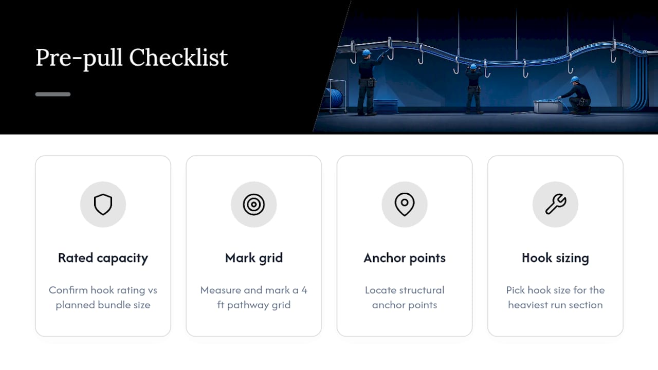
Before pulling cable: confirm the hook’s rated capacity against your planned bundle size, measure and mark a 4 ft grid along the pathway, locate structural anchor points, and pick hook size based on the heaviest section of the run rather than the average.
During installation: photograph the completed layout at each major run, log which support type went where (hook size, anchor point, spacing interval), and test link performance after cable is seated. If a bundle grows beyond what the original plan anticipated, that’s a design change, not a field improvisation. Escalate it. Documenting spacing and support types with photos before and after installation makes certification and future inspections far faster, since nobody has to guess what’s behind the ceiling tile six months later.
Facilities teams managing buildings with a mix of copper, fiber, and security cabling often find that keeping a support log alongside cable slack records pays off the first time a tenant fit-out disturbs an existing pathway. Reviewing cable slack management practices alongside your support documentation closes that gap.
— Ken
Need a Contractor to Handle the Layout?
A professional cabling contractor is the alternative to guessing at spacing on a ladder with a tape measure and hoping the inspector doesn’t notice. Where a DIY install leaves you re-anchoring hooks after a failed inspection, a licensed crew designs the support layout, documents it, and certifies the finished links before the ceiling closes up.

For commercial offices, server rooms, and telecom closets across New York City, structured CAT6 cabling installation from Cables and Chips includes planned support spacing, code-compliant anchoring, and tested, certified links, backed by more than 40 years of experience in commercial environments. If your building also runs security, consider how data and access-control cabling share pathway space with a partner like Tawy Systems’ corporate security solutions in mind. When a job involves heavy bundles, mixed fiber and copper runs, or ceiling grid conditions that complicate anchoring, a no-obligation site survey settles the layout before anyone climbs a ladder. Visit the Cables and Chips services page to request one.
Primary Standards and Datasheets Worth Keeping on File
Save these documents to your job file before you start layout work, not after an inspector asks for them.
ANSI/TIA‑569 sets the hard 5 ft maximum for non-continuous supports and is the document to cite if a spacing decision is ever challenged. The BICSI TDMM covers the practical 4 to 5 ft working range and future-capacity planning in far more depth than any blog post can. The CADDY 2-inch J-hook datasheet gives real capacity numbers by cable type, and Anvilfield’s cabling pathway field guide covers mounting rules and ceiling grid restrictions in practical detail. Keep PDFs of all four in the job folder for certification and future inspections.
Sources
- CADDY 2" J-Hook product data (EANixter / product PDF)
- Cabling pathways and firestop field guide for data centers — Anvilfield
- Electricaltechnology
FAQ
How Many Cat6 Cables Can a 2-Inch J-Hook Hold?
A 2-inch J-hook typically holds about 50 to 60 Cat6 cables, or roughly 27 to 35 Cat6A cables, depending on the manufacturer and cable jacket thickness. Always verify against the specific hook’s datasheet rather than assuming one brand’s rating applies to another.
How Far Apart Should J-Hooks Be Spaced?
The working rule is 4 to 5 ft on center, with ANSI/TIA‑569 setting 1.5 m (5 ft) as the absolute maximum for non-continuous supports. Tighten that spacing to roughly 3 ft near corners, drops, and heavy bundles to control sag.
How Far Can Cable Span Without Support?
For low-voltage structured cabling, the answer is the same 5 ft maximum set by TIA‑569, though heavier bundles and fiber runs should be supported closer to every 3 to 4 ft. This differs from Romex or other electrical wiring spans, which fall under separate electrical code provisions rather than telecommunications pathway standards.
How Do You Properly Mount J-Hooks?
Anchor J-hooks to structural members, beams, or approved hangers, never to a suspended ceiling grid, which isn’t rated to carry cable loads. At beam crossings, mount at least one hook directly to the beam, and keep supports within 24 in of any cable drop.
Can Cables and Chips Design J-Hook Layouts for My Building?
Yes. Structured CAT6 cabling installation from Cables and Chips includes support layout planning, code-compliant mounting, and certified testing for commercial spaces across New York City. Pricing depends on project scope and is available after a site survey.