

Wireless infrastructure is defined as a system where wireless access points (APs) depend entirely on a physical wired backbone to deliver data, power, and network connectivity to end users. Understanding how wireless infrastructure is wired means recognizing that Wi-Fi does not replace cabling. It extends it. Enterprise fiber links routinely achieve 10 Gbps throughput, and PoE++ delivers up to 90W per port to power high-performance APs. The wired backbone is what makes wireless performance possible. Without it, even the most advanced Wi-Fi 7 deployment fails under load.
How wireless infrastructure is wired at the physical layer
The physical layer of any wireless network is copper or fiber cabling running from a network closet to each access point. That cable carries both data and power. The industry term for this physical foundation is structured cabling, and it is the non-negotiable starting point for any wireless deployment.

Category 6a copper cabling
Category 6A is the current standard for wireless AP connections in commercial environments. It supports 10 Gbps throughput over runs up to 100 meters. That bandwidth headroom matters because Wi-Fi 7 APs can aggregate multi-gigabit wireless traffic from dozens of clients simultaneously. Deploying Cat5e or even Cat6 in a Wi-Fi 7 environment creates an immediate bottleneck at the cable itself. Review the CAT6A vs fiber decision before specifying cable for new AP installations.
Fiber optic backbone links
Fiber optic cabling serves as the backbone between MDF and IDF closets in multi-floor or multi-building deployments. Single-mode fiber supports distances well beyond copper’s 100-meter limit, making it the correct choice for inter-building runs or high-density campus environments. Hybrid fiber cables that combine data transmission with power delivery are an emerging option that simplifies infrastructure in new construction. For existing buildings, fiber handles the backbone while Cat6A handles the final drop to each AP.
PoE and power delivery
Power over Ethernet is the mechanism that eliminates the need for a separate electrical circuit at every AP location. PoE++ (IEEE 802.3bt) supports up to 90W per port, which covers the full power budget of current Wi-Fi 7 APs with room for future expansion. Cable bundling directly affects PoE performance. Heat buildup from bundled cables attenuates signal and reduces throughput. Best practice is to use individually shielded Cat6A cables and limit bundle sizes to maintain multi-gigabit speeds across the full cable run.
Pro Tip: When planning PoE runs for Wi-Fi 7 APs, derate your cable bundle size by 20% compared to standard data-only runs. Heat is the silent killer of 10 Gbps performance in dense AP deployments.
How do wireless network architectures integrate wired components?
The structure of wireless networks varies by where control and data processing happen. Each architecture places different demands on the wired backbone. Understanding these differences helps IT teams provision uplinks correctly and avoid congestion.
Three primary WLAN architectures are in use today:
-
Autonomous APs. Each AP manages its own configuration, security, and client associations independently. This model works for small deployments but becomes unmanageable at scale. Wired requirements are straightforward: one Cat6A drop per AP, connected to a PoE switch.
-
Centralized WLC architecture. A Wireless LAN Controller (WLC) manages hundreds to thousands of APs. Client traffic is tunneled from each AP to the WLC via CAPWAP protocol, then forwarded to the network. This tunneling adds overhead to every uplink between the AP and the controller. Uplinks must be provisioned to handle both client data and CAPWAP control traffic simultaneously. Insufficient uplink bandwidth creates bottlenecks that degrade wireless performance across the entire controller domain.
-
Cloud-managed architecture. Platforms like Cisco Meraki and Aruba Central keep data forwarding local at the AP while pushing configuration and monitoring to a cloud controller. This reduces wired uplink load compared to full CAPWAP tunneling. The wired backbone still carries all client data, but the control plane overhead is minimal. This model is increasingly common in enterprise environments because it combines local forwarding efficiency with centralized visibility.
The key design principle across all three models is the same: control and data planes are distinct, and the wired network must be provisioned to support both. Segmenting AP traffic into dedicated VLANs on the wired network is standard practice. It isolates wireless client traffic from wired infrastructure traffic and simplifies security policy enforcement.
What are best practices for wired connections in wireless setups?
Setting up wired connections for wireless networks correctly from the start prevents the majority of performance and reliability problems that surface later. The following practices apply to commercial wireless network setup in office, enterprise, and secure facility environments.
-
Use wired Ethernet for initial AP configuration. Direct Ethernet management connections are standard on APs for a reason. Configuring an AP over Wi-Fi during initial setup introduces the risk of losing the management session mid-configuration. Connect a laptop directly to the AP’s management port via Ethernet before touching any wireless settings.
-
Configure SSIDs, WPA3 security, and radio bands before going live. WPA3 is the current security standard for enterprise wireless. Configure it during initial setup, not as an afterthought. Separate 2.4 GHz and 5 GHz SSIDs or use band steering, depending on your client device mix.
-
Follow cabling standards during installation. Cable runs must meet TIA-568 termination standards. Poor terminations cause return loss and near-end crosstalk (NEXT), both of which reduce effective throughput. Test and certify every run with a Fluke Networks DSX CableAnalyzer or equivalent tool before the AP goes live. Review cable testing certification procedures to understand what pass/fail criteria apply.
-
Plan cable runs for coverage and scalability. Map AP locations against floor plans before pulling cable. Account for future AP additions by installing conduit or leaving pull strings in cable pathways. Retrofitting cable runs in occupied commercial spaces costs significantly more than planning for expansion upfront.
Pro Tip: Label every AP cable at both ends with the AP’s hostname and switch port assignment before terminating. This documentation practice saves hours during troubleshooting and is standard in any well-run network closet.
Wired vs. wireless: how hybrid networks perform better together
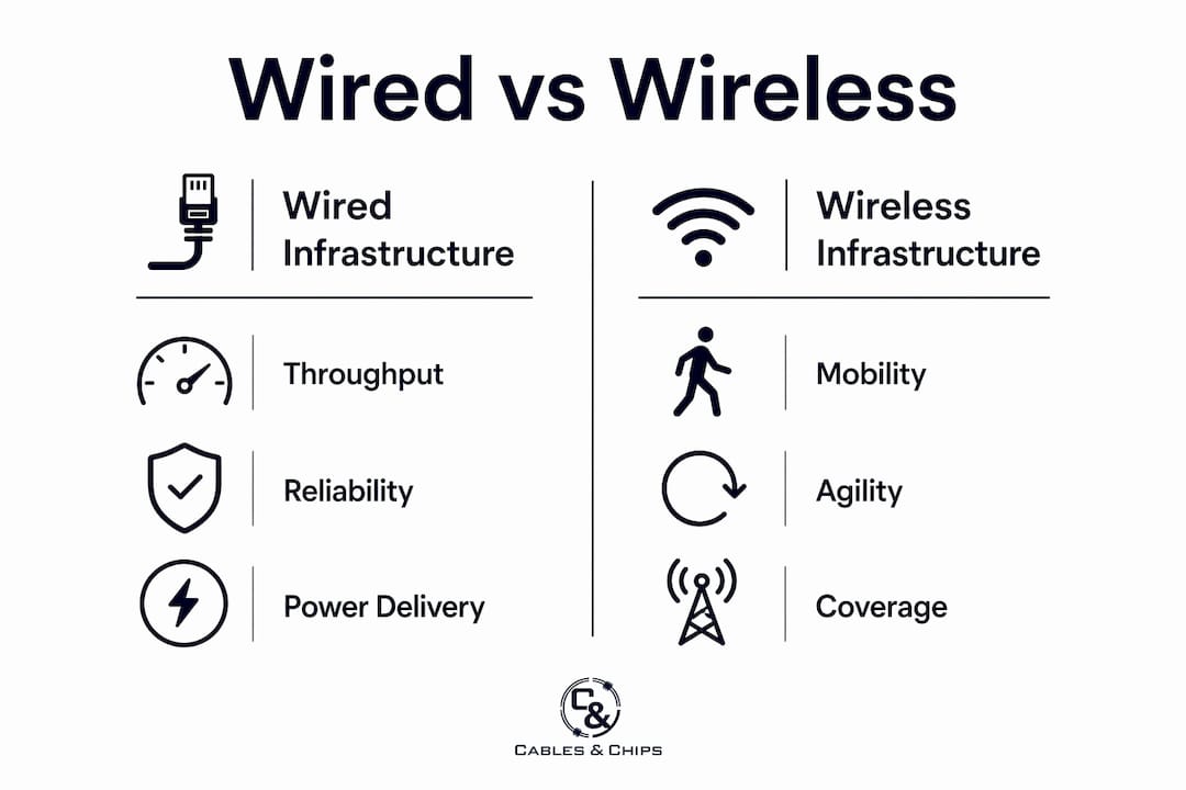
The future of enterprise networking is hybrid by design. Wired and wireless are not competing technologies. They serve different functions within the same infrastructure, and designing them as a unified system produces better performance, security, and manageability than treating them as separate silos.
| Attribute | Wired Infrastructure | Wireless Infrastructure |
|---|---|---|
| Throughput | Up to 10 Gbps per port (Cat6A) | Up to multi-Gbps aggregate (Wi-Fi 7) |
| Latency | Sub-millisecond, consistent | Variable, affected by RF environment |
| Mobility | Fixed endpoint locations | Full user mobility within coverage area |
| Security | Physical access control, stronger isolation | Requires WPA3, VLAN segmentation, monitoring |
| Power delivery | PoE++ up to 90W per port | N/A (receives power via PoE) |
| Best use case | Servers, switches, fixed workstations | Mobile devices, laptops, IoT endpoints |
Wired infrastructure provides the stable, high-capacity backbone. Wireless provides the agile last-mile connection for mobile users and devices. Over 90% of Wi-Fi networks are vulnerable to attacks, which means the wired network’s stronger access controls are not optional. They are the security foundation that wireless depends on.
Unified management systems that handle both wired and wireless from a single platform, such as Cisco DNA Center or Aruba NetEdit, give IT teams consistent policy enforcement across both layers. VLAN segmentation applied at the wired switch level propagates automatically to wireless SSIDs, keeping security policy consistent regardless of how a device connects. For scalable infrastructure examples that unify both layers, structured cabling design is the starting point.
Key takeaways
Wireless performance is determined by the quality of the wired backbone behind it. Every AP, every SSID, and every connected device depends on structured cabling, PoE delivery, and correctly provisioned uplinks to function reliably.
| Point | Details |
|---|---|
| Wired backbone is non-negotiable | Cat6A or fiber optic cabling must connect every AP to the network for reliable wireless performance. |
| PoE++ powers modern APs | IEEE 802.3bt delivers up to 90W per port, covering Wi-Fi 7 AP power requirements without separate electrical circuits. |
| Architecture determines uplink load | CAPWAP tunneling in centralized WLC deployments adds overhead; uplinks must be provisioned to handle both control and data traffic. |
| Cable quality affects throughput | Bundle size, shielding, and termination quality directly impact whether Cat6A delivers its rated 10 Gbps performance. |
| Hybrid design outperforms siloed design | Unified wired and wireless management with consistent VLAN segmentation produces better security and reliability than separate systems. |
What 40 years of cabling work taught me about wireless networks
The most persistent misconception I encounter is that wireless infrastructure means fewer wires. Facilities managers sometimes push back on cabling budgets for Wi-Fi deployments because they assume wireless reduces infrastructure cost. It does not. Every AP is a wired device that happens to broadcast a radio signal. The cable behind it is just as critical as the cable behind a workstation.
The second thing I have learned is that uplink provisioning is where most enterprise wireless problems originate. Teams spend significant budget on high-end APs and then connect them to switches with 1 Gbps uplinks. A single Wi-Fi 7 AP can push more than 1 Gbps of aggregate client traffic. When you add CAPWAP tunneling overhead on top of that, a 1 Gbps uplink becomes the bottleneck for an entire floor.
PoE attenuation from cable bundling is the third issue I see consistently underestimated. Pulling 24 Cat6A cables through a single conduit and expecting full PoE++ performance from all of them is not realistic. Heat builds, resistance increases, and power delivery drops. The fix is straightforward: use shielded Cat6A, limit bundle sizes, and test every run before the AP goes live.
The teams that get wireless right treat it as an extension of their structured cabling program, not a separate project. They plan AP locations alongside cable pathways, specify the correct cable grade from the start, and document every run. That discipline is what separates a wireless network that performs consistently from one that generates help desk tickets every week.
— Ken
Build the wired foundation your wireless network requires
Reliable wireless performance starts with the right physical infrastructure. Cables installs structured cabling systems designed specifically to support high-density wireless deployments in commercial offices, secure facilities, and enterprise environments across New York City.
From CAT6A installation to fiber optic termination and full network closet organization, Cables handles every component of the wired backbone your wireless infrastructure depends on. With more than 40 years of experience in NYC commercial environments, the team at Cables & Chips delivers infrastructure that is tested, documented, and built to perform. Contact Cables at 20 Vesey Street, Lower Manhattan, to schedule a site survey.
FAQ
What wiring does a wireless access point require?
Every wireless access point requires a Cat6A or fiber optic Ethernet connection to the wired network for data, plus PoE delivery for power. Direct Ethernet connections are also required for stable initial configuration.
Why does wireless infrastructure still need structured cabling?
Wireless access points are wired devices that broadcast radio signals. Structured cabling provides the bandwidth, power, and physical security that wireless radio alone cannot deliver.
What is CAPWAP and how does it affect wired infrastructure?
CAPWAP is the tunneling protocol used in centralized WLAN architectures to carry AP-to-controller traffic. CAPWAP tunneling overhead increases uplink bandwidth consumption, requiring higher-capacity wired uplinks between APs and the WLC.
How does PoE++ support wi-fi 7 access points?
PoE++ (IEEE 802.3bt) delivers up to 90W per port over Cat6A cabling, meeting the full power budget of current Wi-Fi 7 APs. Cable bundle size and shielding must be managed carefully to prevent heat-related power attenuation over longer runs.
What is the difference between centralized and cloud-managed wireless architectures?
Centralized architectures tunnel all client traffic through a physical WLC via CAPWAP, increasing wired uplink load. Cloud-managed systems keep data forwarding local at the AP while using cloud platforms for configuration and monitoring, reducing wired infrastructure overhead.