
Structured cabling is the standardized physical layer of your office network, designed to support voice, data, video, and security systems through a single, organized infrastructure. When you plan a structured cabling office buildout correctly, you avoid costly retrofits, network bottlenecks, and compliance failures. This guide walks project managers and office professionals through every phase, from site survey to certification, using TIA-568 standards and real-world capacity targets. Cables & Chips has spent more than 40 years building this infrastructure across New York City commercial spaces, and the process below reflects what actually works.
How to plan structured cabling for an office buildout
The first step is understanding that structured cabling is not a finishing trade. Treating it as one leads to expensive installation problems and operational bottlenecks that follow the building for years. Cabling belongs in the planning phase, alongside mechanical, electrical, and plumbing. Involve your low-voltage contractor before the general contractor frames a single wall.
The industry standard governing this work is TIA-568, which defines performance requirements for copper and fiber cabling systems in commercial buildings. Knowing this standard exists matters because it sets the pass/fail benchmarks your installer must meet. Any reputable contractor will design and certify to TIA-568 from day one.

Your network is only as strong as the infrastructure behind it. A well-documented, tested, and labeled cabling system reduces troubleshooting time, supports future upgrades, and satisfies warranty requirements. Start with that mindset and every decision downstream becomes clearer.
What does a site survey and drop list include?
A site survey is the foundation of every successful office cabling installation. Walk the floor plan with your cabling contractor and mark every location that needs a network connection. A thorough drop list includes workstations, conference rooms, wireless access points, VoIP phones, printers, and security cameras.
Distance matters as much as location. Copper runs are limited to 295 feet (90 meters) from the patch panel to the endpoint. Measure every run from the proposed MDF or IDF location. If any run exceeds that threshold, you need an intermediate switch or a fiber uplink to a secondary IDF.
Document every drop with a unique identifier, its endpoint type, and its distance from the telecom room. This becomes your as-built reference and your contractor’s installation guide. Use floor plan software like AutoCAD or Bluebeam to mark drops visually so the entire project team works from the same document.
- Mark workstation drops (typically two per desk in modern offices)
- Identify wireless AP locations based on coverage modeling
- Flag all VoIP phone locations, including reception and conference rooms
- Note CCTV and access control device locations for PoE planning
- Confirm telecom room locations and measure backbone routes
Pro Tip: Add 10–15% more drops to your list than you think you need before finalizing it. Moves, adds, and changes happen within the first year of occupancy, and a spare drop costs far less during installation than a retrofit later.
How do you future-proof your office cabling system?
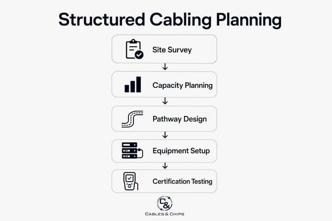
Capacity planning is where most office buildouts fall short. Design for at least 50% more network drops than your current headcount requires. If you need 80 drops today, design for 120. That buffer absorbs growth without requiring a full recabling project.
Power over Ethernet (PoE) planning is equally critical. Cameras, wireless APs, VoIP phones, and digital signage all draw power through the cable. IEEE 802.3af delivers up to 15.4W at the switch port, with approximately 12.95W reaching the device. Plan your switch power budget with margin, not just enough for today’s device count.
Here is a practical capacity planning sequence:
- Count all current devices by type and PoE class requirement
- Project device growth over a three-year horizon
- Add 50% to your total drop count as a growth buffer
- Calculate total PoE wattage demand and select switches with 20% headroom above that figure
- Specify CAT6A cable for all runs to support 10-Gigabit speeds and higher PoE efficiency
Conduit and pathway capacity follows the same logic. Fill conduit to no more than 40% of capacity during initial installation. That remaining space lets you pull additional cables later without tearing open walls or ceilings.
Budget ranges for this work run from $150 to $350 per data drop, depending on cable type, labor rates, and pathway complexity. Plenum-rated cable and conduit installations push costs toward the higher end. Build that range into your project budget early, before scope is locked.
Pro Tip: Specify CAT6A rather than CAT6 for new buildouts. The cost difference per drop is modest, but CAT6A supports 10GbE at full 100-meter distances and handles higher PoE loads with less heat buildup in bundled cable runs.
What goes into network closet and backbone planning?
The network closet, also called the MDF (Main Distribution Frame) or IDF (Intermediate Distribution Frame), is the hub of your cabling system. A minimum 6×8-foot telecom room suits a small office. Larger deployments need proportionally more space, and every room needs dedicated power circuits, ventilation, and physical security.
Validate telecom room placement early. Run length, power availability, ventilation capacity, and rack space all affect where the room can go. Moving it after construction begins is expensive. For detailed guidance on sizing and layout, the network closet planning guide from Cables covers the full equipment list and spatial requirements.
Every MDF and IDF should include the following equipment as standard:
| Equipment | Function |
|---|---|
| Managed switches | Connect endpoints and enforce network policy |
| Patch panels | Terminate horizontal cable runs for organized cross-connection |
| Firewall/router | Control traffic between internal network and WAN |
| UPS (uninterruptible power supply) | Protect equipment from power interruptions |
| Cooling unit or ventilation | Maintain safe operating temperatures for active gear |
Backbone cabling connects your MDF to each IDF across floors or wings. Use fiber optic cable for backbone runs longer than 100 meters or where electrical interference is a concern. For shorter inter-closet runs in smaller buildings, CAT6A copper is acceptable. The CAT6A vs. fiber decision guide from Cables walks through the tradeoffs in detail.
When should you plan cable pathways and schedule installation?
Pathway planning and installation timing directly control your project cost. Engaging cabling contractors before walls are framed or ceilings are closed costs significantly less than retrofitting after finishes are in place. Retrofitting can cost two to three times more in labor alone.
“The single most expensive mistake in an office buildout is scheduling the cabling contractor after the drywall crew. By that point, every pathway costs double and every timeline slips.”
Cable routing options include conduit, cable trays, underfloor systems, and open plenum spaces. Each has tradeoffs in cost, flexibility, and code compliance. Conduit offers the best long-term serviceability. Cable trays work well in open ceilings. Underfloor systems suit raised-floor environments like trading floors or data centers. ANSI/TIA-569-D governs pathway design and recommends planning capacity margins to avoid difficult future cable pulls.
Coordinate your cabling schedule with the general contractor’s construction timeline. Cabling rough-in should follow electrical rough-in and precede drywall. Trim-out, which includes terminating jacks and installing faceplates, happens after painting. Certification testing runs last, before occupancy. For subcontractor scheduling and estimating coordination, resources like TradeBid’s construction blog offer practical guidance on sequencing trades.
How does cable certification testing work?
Certification testing is the proof that your cabling system performs to specification. Testing follows TIA-568.2-D for copper and TIA-568.3-D for fiber. Every run must pass before the project is accepted. Learn more about the full process at cable testing certification.
Two test topologies apply to copper certification:
- Permanent link: Tests the installed cable from the patch panel port to the wall jack, excluding patch cords. This is the most common acceptance test for new installations.
- Channel: Tests the complete end-to-end path including patch cords. Used when the full channel performance matters for a specific application.
Select your test topology early and apply it consistently across all runs. Mixing topologies in a single project creates inconsistent results and complicates warranty claims.
Key measurements in every certification report include:
| Test Parameter | What It Measures |
|---|---|
| Wiremap | Correct pin-to-pin connections and absence of shorts or opens |
| Insertion loss | Signal attenuation across the run length |
| NEXT (Near-End Crosstalk) | Interference between adjacent pairs at the transmit end |
| Return loss | Signal reflected back toward the source |
| Propagation delay | Time for signal to travel the full cable length |
Certification results include pass/fail status for each parameter against the category standard. A single fail on any parameter means the run does not meet spec and must be repaired or replaced before acceptance.
Store all test reports, as-built drawings, and labeling records in a shared project folder accessible to your IT team and facilities manager. This documentation supports warranty claims, future troubleshooting, and any moves or changes after occupancy.
Pro Tip: Require your contractor to deliver test reports in PDF and in the native format of the test instrument (such as .flw files from Fluke Networks DSX CableAnalyzer). Native files cannot be edited and provide legally defensible proof of compliance.
Key takeaways
A successful office cabling buildout requires early contractor involvement, accurate capacity planning, and certified documentation before occupancy.
| Point | Details |
|---|---|
| Involve cabling contractors early | Engage your low-voltage contractor before walls are framed to avoid retrofit costs two to three times higher. |
| Build a complete drop list | Document every endpoint type, location, and distance from the MDF/IDF before any cable is pulled. |
| Plan for 50% more capacity | Design for at least 50% more drops and conduit fill than current needs to support future growth. |
| Size telecom rooms correctly | A minimum 6×8-foot room with power, cooling, and security is required even for small office deployments. |
| Certify every run | Test all copper runs to TIA-568.2-D and store reports with as-built drawings for warranty and compliance. |
What i’ve learned after 40 years of office cabling projects
The most persistent mistake I see on office buildout projects is treating structured cabling as a detail to handle after the real construction work is done. Project managers hand the cabling scope to whoever is available last, schedule it between painting and furniture delivery, and then wonder why the network is unreliable on day one.
Cabling is infrastructure. It belongs in the same planning conversation as HVAC and electrical. When the GC, electricians, IT team, and cabling contractor sit in the same room during schematic design, the project runs cleaner, faster, and cheaper. Conflicts get resolved on paper instead of in the ceiling.
On future-proofing, I will say this: the 50% capacity buffer is not a luxury. I have watched companies recable entire floors within 18 months of moving in because the original design had no headroom. The cost of those extra drops during construction is trivial compared to the disruption of a recabling project with 200 people trying to work around you.
Certification documentation is the part most clients undervalue until they need it. When a run fails two years after occupancy, a complete set of test reports tells you exactly which cable, which panel port, and which wall jack is the problem. Without it, you are guessing.
— Ken
Plan your office cabling project with Cables
Cables & Chips has delivered structured cabling buildouts across New York City commercial offices for more than 40 years, from small professional suites to enterprise floor builds. Whether you are specifying structured cabling system components for a new buildout or need a full CAT6 and CAT6A installation with certified test documentation, Cables brings the technical depth and field experience to get it right the first time.
Every project starts with a site survey and a detailed scope of work. Contact Cables & Chips at 20 Vesey Street in Lower Manhattan to schedule your consultation. Low Voltage. High Performance.
FAQ
What is structured cabling in an office buildout?
Structured cabling is a standardized system of cables, connectors, and hardware that supports all voice, data, and low-voltage systems in a commercial building. It follows TIA-568 standards and provides a single, organized infrastructure for the entire office network.
How many network drops does an office need?
Plan for at least two drops per workstation plus additional drops for wireless APs, VoIP phones, printers, and security cameras. Design for 50% more total drops than your current device count to accommodate future growth without recabling.
What is the maximum cable run length for cat6 or cat6a?
The maximum copper run length for CAT6 and CAT6A is 295 feet (90 meters) for horizontal cabling under TIA-568. Runs exceeding this limit require an intermediate IDF or a fiber uplink to maintain performance.
How long does an office cabling installation take?
A typical office cabling installation runs two to four weeks from rough-in through certification, depending on drop count, pathway complexity, and coordination with other trades. Scheduling the cabling contractor early in the construction sequence prevents delays.
Why does cable certification matter for office projects?
Certification testing proves each cable run meets the performance standard for its category under TIA-568.2-D. Test reports support manufacturer warranties, satisfy insurance requirements, and give your IT team a documented baseline for future troubleshooting.