Understanding how server rack cabling works is the difference between a data center that runs smoothly and one that costs you hours of troubleshooting every time something breaks. Poor cabling causes unplanned downtime, blocks airflow, and turns a 10-minute swap into a 2-hour cable-tracing exercise. Structured cabling, the formal discipline behind organized rack infrastructure, addresses all of this through documented layers, tested components, and consistent physical standards. This guide covers the mechanics, best practices, and operational realities every network administrator needs to know.
Key Takeaways
| Point | Details |
|---|---|
| Structured cabling has distinct layers | Permanent links and patch cords serve different roles; mixing them up creates maintenance problems. |
| Cable manager placement is deliberate | Position 1U managers above or below patch panels based on cord direction to protect bend radius. |
| Patch cord length selection matters | Measure the actual routing path, not the straight line, to avoid slack buildup or cords under tension. |
| Documentation must be current | TIA-606 requires records updated within 24 hours of any move, add, or change to prevent troubleshooting failures. |
| Cabling directly affects cooling | Cable bundles placed over vents or intake paths raise rack temperatures and accelerate hardware failure. |
How server rack cabling works: the foundational architecture
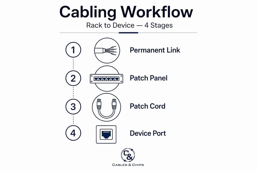
Before you can organize or troubleshoot a rack, you need to understand the two distinct physical layers that make up any properly built installation.
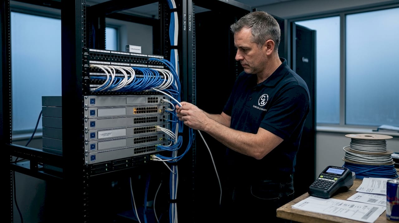
The Permanent Link is the fixed, certified infrastructure. These are the horizontal runs you pull through conduit or cable tray from patch panels back to equipment rooms. Once tested and certified, this cabling does not get touched unless something breaks. The Cross-Connect layer sits on top of it. These are the patch cords connecting switches to servers, panels to active gear, and everything in between. They are flexible, replaceable, and the most frequently disturbed component in any rack.
The patch panel is the demarcation point between these two layers. It protects your certified permanent cabling from daily operational contact. Every move, add, or change happens at the patch panel level, not at the horizontal run. This is how you preserve the integrity of your tested infrastructure over years of operation.
Here is a breakdown of the core components and their roles:
| Component | Function | Key Constraint |
|---|---|---|
| Patch panel | Terminates permanent cabling; demarcation point | Fixed position; do not reuse ports arbitrarily |
| 1U horizontal cable manager | Routes patch cords between panel and switch | Fill capacity ≤50% to allow future growth |
| Vertical cable manager | Handles longer runs along rack sides | Bend radius ≥4× cable diameter for copper |
| Patch cords (Cross-Connect) | Connect active gear; absorb MACs | Must match port-to-port routing path length |
| Cable tray | Overhead or underfloor inter-rack routing | Must align with rack rows and airflow paths |
One physical constraint that gets ignored too often is bend radius. For copper cabling, bend radius must be at least four times the cable diameter. Fiber requires ten times. Violating these minimums degrades signal quality and, over time, damages the cable physically. High-density racks running MPO fiber actually require 1.5U of cable management space per 1U of equipment because of the larger bend radius and cable bulk involved.
The structured copper channel also carries a hard 100-meter length limit: 90 meters for the permanent link plus 10 meters for patch cords. Exceeding this degrades performance on CAT6 and CAT6A channels and will cause certification failures.
Routing and organizing cables within a rack
Knowing the components is one thing. Knowing how to route them correctly is where most racks succeed or fail. The standard patching geometry that produces clean, maintainable racks is straightforward: patch panel, then 1U cable manager, then switch. Every port on the panel connects through the manager before reaching the active gear below or above it.
The reason this geometry works is behavioral. Technician behavior follows the path of least resistance. When a 1U manager is correctly positioned between a panel and a switch, the natural routing path is also the correct one. When it is not, technicians improvise, and improvisations accumulate into the cable chaos that makes racks unmaintainable.
Follow these steps when planning your cable routing sequence:
- Define your rack layout on paper before running a single cable. Map which U-spaces hold patch panels, managers, switches, and servers.
- Install patch panels and cable managers first, before mounting active gear. This gives you full access to route cleanly.
- Route all patch cords through the horizontal manager before connecting to switch ports. Never run cords across the face of equipment.
- Use vertical managers for any cord that travels more than 2U in either direction. Do not drape long cords across panels.
- Keep power cables and data cables on opposite sides of the rack whenever possible. Power runs on the left, data on the right, is a widely adopted convention that reduces electromagnetic interference.
- Leave service loops at both ends of every cord. A 3-inch loop at each connector gives you enough slack to re-dress cords or shift equipment without pulling on live connectors.
Pro Tip: Place your 1U horizontal manager on the side closest to where the cord exits the patch panel port. If your patch panel faces the front and the cord exits forward, place the manager directly below the panel so the cord turns into the manager without forming a sharp angle at the connector boot.
One more consideration for routing: rack fill capacity. Cable fill should not exceed 50% of any manager’s rated capacity. This is not about aesthetics. Overfilled managers make future additions physically impossible and increase the likelihood of damaging existing cords during any maintenance activity.
Patch cord lengths and labeling strategies
Patch cord length selection is where experienced technicians separate themselves from the rest. The instinct is to grab a cord that looks long enough. The correct approach is to measure the actual routing path the cord will travel through the manager, not the straight-line distance between two ports.

A cord going from panel port 1A to a switch directly below it through a 1U manager might travel 24 inches on the actual path even though the two ports are 3 inches apart vertically. Buy a 2-foot cord. Buy a 3-foot cord and you have a pile of slack sitting in the manager. Buy a 1-foot cord and it will be under tension every time the switch shifts slightly.
Standardized length ladders simplify this. Most experienced teams stock only a few defined lengths, typically 1-foot, 2-foot, 3-foot, 5-foot, and 7-foot. Using a constrained set of lengths means your team builds consistent muscle memory for what goes where, and replacements are always on hand.
Key labeling practices:
- Follow ANSI/TIA-606-D hierarchical identifiers. Each cable gets a label tied to a building, floor, room, and port designation. This makes remote troubleshooting possible even when the original installer is unavailable.
- Use printed, heat-shrink labels on patch cords rather than handwritten tape. Tape labels fall off within months in warm rack environments.
- Apply color coding by circuit type or destination. Blue for data, yellow for WAN/uplinks, red for management networks is one common convention. Pick a standard and apply it throughout every rack.
- Update documentation within 24 hours of any move, add, or change. TIA-606 mandates this window specifically because delay is how documentation rot starts. One undocumented change becomes three, then ten, and within six months your records no longer reflect reality.
Pro Tip: Photograph the front of every rack after any scheduled maintenance window. A timestamped image takes 30 seconds and gives you a visual reference that catches undocumented changes before they compound.
For network closet labeling standards that go beyond the rack, the network closet organization guide from Cables covers room-level labeling and how it connects to rack-level identifiers.
Cabling’s impact on airflow and cooling
Most IT professionals understand that cooling matters. Fewer recognize that their cabling decisions directly control how well cooling actually works.
Cable bundles placed over the top of servers or routed across air intake vents create dead zones where cool air cannot reach components. A 2U bundle of 20 patch cords sitting across a server’s front intake is effectively a partial blockage. It does not stop airflow completely, but it reduces it enough to raise inlet temperatures. Over weeks, this shortens component lifespan.
The relationship between cabling and cooling follows hot-aisle/cold-aisle containment logic:
- Cold air is supplied from the front of equipment rows. Route cables so they do not cross this zone. Use the rear and sides of racks for cable trays wherever possible.
- Cable trays must align with rack rows rather than cutting across them. A tray that runs perpendicular to rack rows creates a thermal barrier that disrupts containment.
- Keep overhead cable trays positioned above the hot aisle, not the cold aisle. Trays above cold aisles restrict the cold air supply path before it reaches equipment.
- Avoid bundling more than 24 copper cables together in a single horizontal manager run. Oversized bundles generate their own localized heat and reduce the effectiveness of any airflow passing through the manager.
The practical takeaway: cable tray design is part of your cooling infrastructure, not separate from it. Plan it alongside your airflow containment strategy, not after the fact.
Common pitfalls and how to avoid them
The mistakes that create the worst rack problems are not the ones that happen during installation. They are the ones that happen during the months and years after installation, when documentation slips and shortcuts accumulate.
- Running cables before finalizing rack layout. The most common failure mode is terminating cables before the rack layout is locked. You end up with awkward terminations, cords under tension, and gear that cannot be repositioned without re-running cable.
- Using zip ties instead of hook-and-loop fasteners. Zip ties are permanent and cut into cable jackets when overtightened. Use Velcro-style hook-and-loop straps throughout. They allow adjustments without damaging cabling.
- Ignoring shielding and grounding in high-EMI environments. Racks near UPS systems, generators, or heavy electrical infrastructure need shielded patch panels and shielded cords. Unshielded copper in a high-EMI zone produces errors that look like hardware failures during troubleshooting.
- Buying cable managers without capacity planning. A 24-port patch panel will have more than 24 cords if you account for service loops. Plan for the fully dressed count, not just the port count.
- Skipping the documentation update after changes. Documentation rot is the leading cause of extended troubleshooting time. When records do not match physical reality, every incident takes longer to resolve.
Pro Tip: Assign a single team member ownership of rack documentation updates during any change window. Shared ownership means no one takes responsibility, and the records drift.
What I have learned after years of server rack work
I have walked into hundreds of racks across New York City, and the ones that cost clients money are rarely the result of bad cable. They are the result of bad process.
Most cabling problems stem from poor change management rather than installation errors. The original install is usually fine. What breaks it is six months of undocumented moves, zip-tied additions, and “temporary” patch cords that become permanent. The permanent infrastructure holds up. The patch layer drifts.
What I have found actually reduces troubleshooting time is not a neater rack. It is a disciplined patch cord discipline where every cord has a defined path, a label, and a record. When that is in place, a connectivity issue takes minutes to isolate. When it is not, you are tracing cords by hand through a rack that nobody documented since 2022.
I have also learned that planning for scalability is not about leaving empty space. It is about leaving accessible space. A rack that is 60% full with clean routing is far more scalable than one that is 40% full with cords running everywhere. Accessibility is what makes growth possible without rebuilding.
My honest take: the technical standards, TIA-606, ANSI bend radius specs, the 50% fill rule, are not bureaucratic checkboxes. They are distilled operational experience. Following them does not just make your rack look better. It makes your team faster and your infrastructure more reliable when it matters most.
— Ken
Take your server rack setup further
If your current rack infrastructure is overdue for cleanup, recertification, or a full rebuild, Cables works with IT departments and building management teams across New York City to deliver structured cabling that holds up operationally.
Our team installs CAT6 and CAT6A structured cabling to ANSI/TIA standards, handles complete rack builds with documented labeling, and provides scalable infrastructure designs for teams that need room to grow without re-running everything. For environments requiring high-speed backbone connections, we also offer fiber optic installation and termination services built to the same standards. Whether you need a single rack cleaned up or a multi-room data center organized from scratch, Cables brings 40-plus years of low voltage experience to every project. Contact us at 20 Vesey Street in Lower Manhattan or schedule a site survey to get started.
FAQ
What is the difference between permanent link and patch cords?
The permanent link is the fixed, certified horizontal cabling that runs from patch panels to telecommunications rooms. Patch cords are the flexible Cross-Connect layer that connects active gear to patch panels and are replaced during moves, adds, and changes.
How long should patch cords be in a server rack?
Measure the actual routing path through cable managers, not the straight-line distance between ports. Most teams standardize on 1-foot, 2-foot, 3-foot, 5-foot, and 7-foot lengths to cover common rack scenarios without excess slack.
How does cabling affect server rack cooling?
Cable bundles routed across air intake vents or cold aisles restrict airflow and raise equipment inlet temperatures. Aligning cable trays with rack rows and keeping them above hot aisles preserves containment and prevents localized overheating.
What labeling standard applies to server rack cabling?
ANSI/TIA-606-D provides the hierarchical labeling framework for structured cabling. It requires that documentation records be updated within 24 hours of any move, add, or change to prevent records from drifting out of sync with physical infrastructure.
What is the maximum channel length for structured copper cabling?
The total channel length for structured copper cabling is 100 meters: 90 meters for the permanent link and 10 meters for combined patch cords. Exceeding this limit compromises signal integrity on CAT6 and CAT6A installations.