
How Security Camera Cabling Is Planned for Commercial Sites
TL;DR:
- Proper security camera cabling planning ensures system reliability by following standards for cable length, interference separation, and power budgeting. It emphasizes dedicated star topology wiring, using Cat6A cables, grounding shields correctly, and integrating early with building infrastructure for optimal performance. Avoiding common installation errors prevents costly repairs and coverage gaps, ensuring long-term security effectiveness.
Security camera cabling planning is defined as the process of mapping camera locations, cable routes, power delivery, and network integration before a single cable is pulled. Done correctly, it prevents signal loss, eliminates electromagnetic interference (EMI), and keeps PoE power budgets within switch capacity. The industry term for this discipline is structured CCTV cabling design, and it follows standards including IEEE 802.3 for maximum cable lengths and EN 62676-4 for camera placement classification. Skipping this process does not save time. It creates expensive retrofits, intermittent failures, and coverage gaps that compromise security. How security camera cabling is planned determines whether a system performs reliably for years or fails under load within months.
What are the key standards and technical requirements for security camera cabling?
The IEEE 802.3 standard defines the maximum PoE cable length as 100 meters total: 90 meters of horizontal cabling plus 10 meters of patch cords. Exceeding this limit causes signal degradation, dropped frames, and intermittent camera disconnects. Every cable route must be measured on the architectural plan before installation begins.
EMI separation is equally non-negotiable. Security cabling must maintain at least 50mm from mains power and 300–500mm from high-interference sources like Variable Frequency Drives (VFDs). Violating these clearances introduces noise that appears as interference lines on video or causes cameras to reboot randomly.
PoE power standards also govern design decisions. The three main tiers are:
- IEEE 802.3af (PoE): up to 15.4W per port, suitable for basic fixed cameras
- IEEE 802.3at (PoE+): up to 30W per port, covers most PTZ and IR cameras
- IEEE 802.3bt (PoE++): up to 90W per port, required for high-power multi-sensor cameras
A 24-port PoE+ switch with a 370W budget cannot power 24 cameras drawing 30W each simultaneously. That math produces 720W of demand against a 370W supply, causing intermittent failures that are notoriously difficult to diagnose. Calculating the total power draw across all connected devices is a required step in any professional cabling plan.
Pro Tip: Always add a 20% power buffer above your calculated PoE draw. Switch manufacturers rate total budgets conservatively, and real-world draw under full load often exceeds spec sheet estimates.
| Standard | Max Power Per Port | Typical Use Case |
|---|---|---|
| IEEE 802.3af | 15.4W | Basic fixed IP cameras |
| IEEE 802.3at | 30W | PTZ, IR, and mid-range cameras |
| IEEE 802.3bt | 90W | Multi-sensor and high-power cameras |
How does camera placement and cabling topology affect planning quality?
Effective planning starts with a camera schedule, not a cable reel. Each camera’s function should be classified per EN 62676-4 into one of four levels: Detection, Observation, Recognition, or Identification. A camera covering a parking lot perimeter serves a Detection function and requires wide-angle coverage. A camera monitoring a cash register serves an Identification function and demands high resolution and tight framing. These distinctions drive lens selection, mounting height, and ultimately cable route decisions.
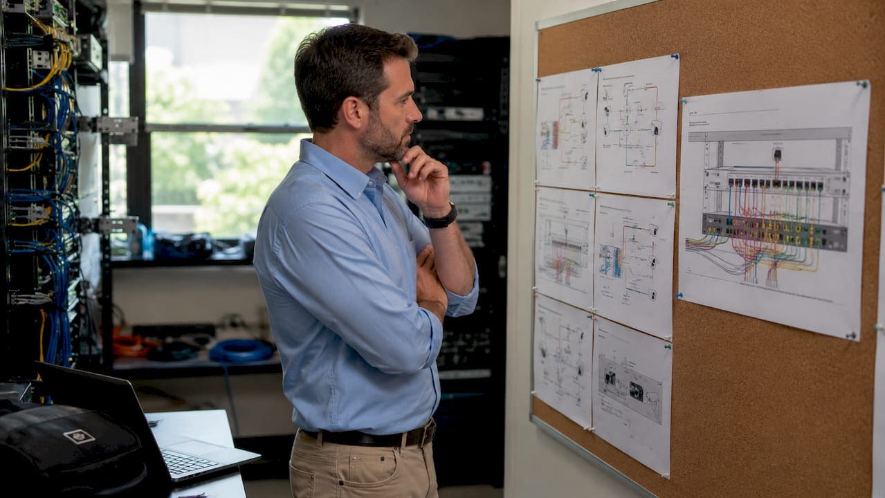
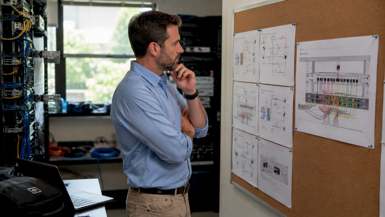
Architectural floor plans with marked cable routes are the working document for any professional installation. Routes must account for ceiling voids, conduit paths, fire compartments, and riser shafts. Planning on paper before touching a wall prevents the most common and costly mistake in security camera installation: discovering mid-project that a cable route is blocked by a structural beam or a fire-rated barrier.
The star or home-run wiring topology, where each camera has a dedicated cable run back to the central switch or NVR, is the only reliable wiring standard for commercial and professional environments. Daisy-chaining cameras through a single cable creates a single point of failure. One cut or one failed connector takes down every camera downstream. Star topology eliminates that risk entirely and makes fault isolation straightforward.
Network closet and NVR placement directly shapes cable route efficiency. Positioning the IDF (Intermediate Distribution Frame) or PoE switch at the geographic center of a camera cluster minimizes the number of runs that approach the 90-meter horizontal limit. Planning for 15–20% spare cable capacity in each conduit also protects against future camera additions without requiring new conduit runs.
What cable types and installation practices optimize reliability?
Cat6A is the recommended cable for new security camera installations. It supports 10Gbps at 100 meters, handles PoE++ heat dissipation better than Cat6, and provides headroom for high-resolution 4K and multi-sensor cameras. Cat6 remains acceptable for lower-density systems running standard PoE, but it reaches its thermal and bandwidth limits faster as camera counts and resolutions increase.
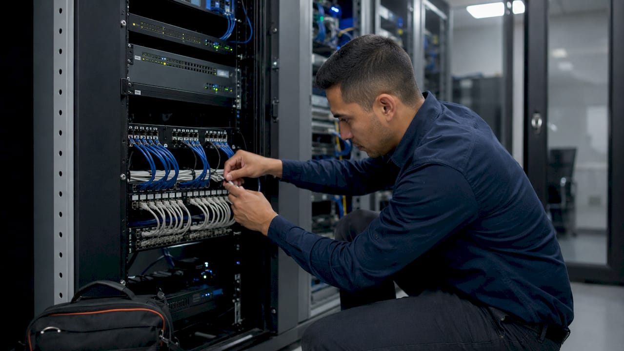
Shielded cable (S/FTP) is required in high-EMI environments such as manufacturing floors, mechanical rooms, and any space with VFDs or large motors. Shielding only works correctly when the shield is grounded at the switch end only. Grounding both ends creates a ground loop that introduces 50Hz hum and visible interference lines on video. This is one of the most common and easily avoided installation errors.
Fiber optic cabling is the correct choice for runs exceeding 100 meters or for inter-building connections. Fiber uplinks between floors or buildings eliminate EMI entirely and support the bandwidth demands of large camera arrays feeding a central NVR. For decision-makers evaluating long-distance runs, the fiber optic infrastructure advantages over copper are significant at scale.
Key installation practices that protect long-term reliability:
- Route CCTV cables in dedicated conduit, separated from mains power
- Cross power lines at 90 degrees where parallel runs cannot be avoided
- Label every cable at both ends with a unique identifier matching the cable schedule
- Document as-built routes on updated floor plans immediately after installation
- Use low-smoke zero-halogen (LSZH) cable in occupied buildings and plenum spaces
Pro Tip: Label cables before you terminate them, not after. Once a cable is dressed into a patch panel, re-labeling requires pulling it back out. Build the habit of labeling at the camera end and the switch end before the first crimp.
How to integrate security camera cabling into building network and electrical infrastructure?
Security camera cabling integrated into the building’s core network design from the start costs significantly less than a retrofit. Early integration allows PoE power budgets and bandwidth requirements to be factored into switch procurement, electrical panel sizing, and conduit allocation before walls are closed. Retrofitting a 32-camera system into a finished commercial space typically requires cutting through fire-rated walls, re-routing conduit, and adding electrical capacity that was never planned for.
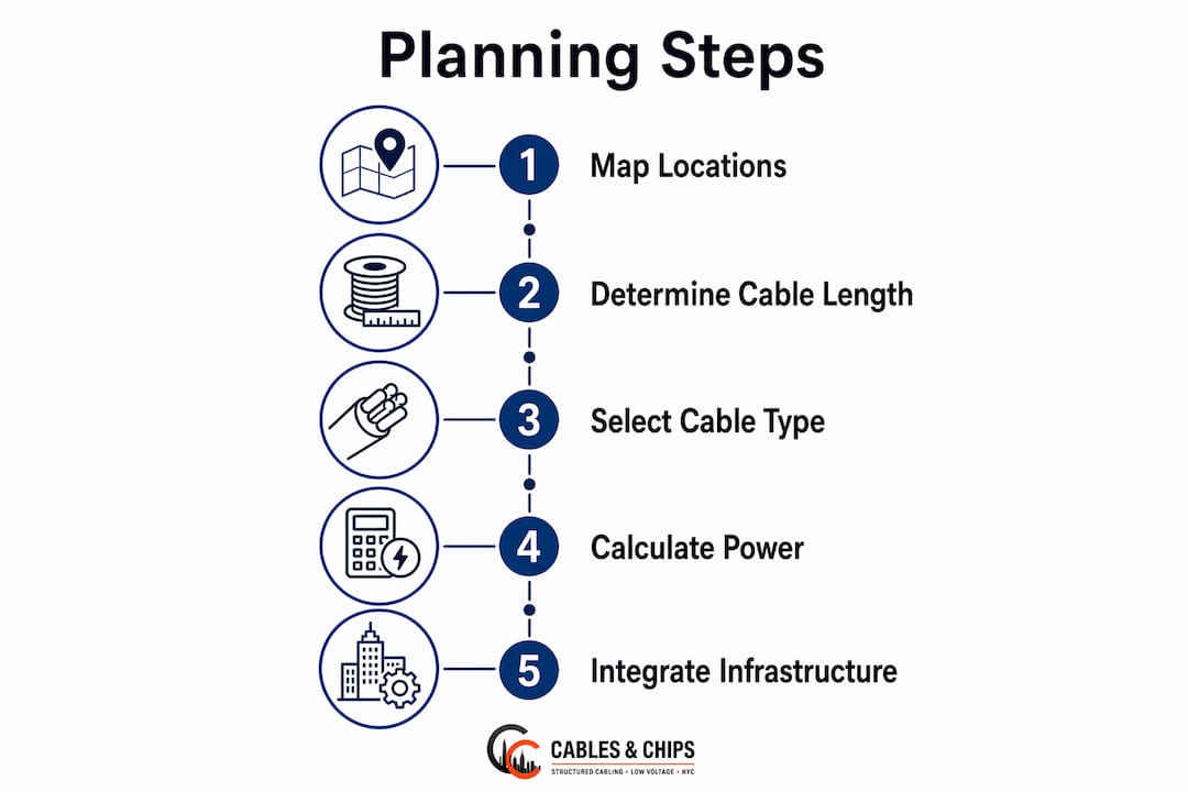
A structured integration process follows this sequence:
- Develop a network topology diagram showing edge switches, core switches, NVR servers, and uplink paths before any procurement begins.
- Coordinate with the electrical contractor to reserve conduit pathways and confirm that PoE switch locations have adequate dedicated circuits.
- Identify fire compartment boundaries and plan cable penetrations with fire-rated seals per applicable electrical codes.
- Select managed switches with VLAN, QoS, and port monitoring features. Segregating camera traffic on a dedicated VLAN prevents surveillance data from competing with business network traffic.
- Plan fiber uplinks between floors and buildings to handle bandwidth aggregation and eliminate EMI on backbone runs.
- Document every decision in a cable schedule that maps each camera ID to its cable label, switch port, VLAN assignment, and PoE class.
Redundancy planning belongs in this phase, not as an afterthought. Mission-critical environments such as data centers, financial trading floors, and secure government facilities require dual NVR paths, UPS-backed PoE switches, and documented failover procedures. Coordinating security camera cabling with access control cabling requirements at this stage also prevents conflicts between two systems that often share conduit and network closet space. For commercial office buildouts, aligning this work with the broader structured cabling office plan from day one produces a cleaner, more maintainable result.
Key Takeaways
Effective security camera cabling planning requires standards compliance, topology discipline, correct cable selection, and early integration with building network and electrical infrastructure.
| Point | Details |
|---|---|
| Follow IEEE 802.3 cable limits | Keep total runs within 100m (90m horizontal + 10m patch) to prevent signal loss. |
| Apply PoE power budgeting | Calculate total device draw and add a 20% buffer to avoid switch overload failures. |
| Use star topology exclusively | Each camera needs a dedicated home-run cable to eliminate single points of failure. |
| Choose Cat6A for new installs | Cat6A handles 10Gbps, PoE++ heat, and high-resolution cameras better than Cat6. |
| Integrate cabling early | Plan camera cabling during initial building design to avoid costly retrofits later. |
What I’ve learned from planning CCTV cabling on commercial projects
The most expensive mistake I see on commercial security projects is treating camera cabling as an afterthought. A project manager calls us after the walls are closed, the conduit is full, and the electrical panel has no spare capacity. At that point, every fix costs three times what it would have cost during the design phase.
The second most common error is PoE power budget miscalculation. Facility managers see a 24-port switch and assume it powers 24 cameras. It does not. A switch rated at 370W total cannot sustain 24 cameras drawing 25W each. The system works fine during commissioning when only a few cameras are active, then starts dropping feeds six months later when the full camera count goes live. That failure pattern is almost always traced back to a power budget that was never calculated.
Grounding errors on shielded cable are the third issue I encounter regularly. Installers ground the shield at both ends because it seems like the right thing to do. It is not. Grounding at both ends creates a ground loop, and that loop produces exactly the kind of interference that shielding was supposed to prevent. Ground the shield at the switch end only, and document that decision in the cable schedule so the next technician does not “fix” it.
My consistent recommendation: treat CCTV as core infrastructure, not a peripheral add-on. It shares conduit, network closets, and switch capacity with every other system in the building. Plan it that way from day one, and the system will perform reliably for the life of the building.
— Ken
Professional cabling support for security camera infrastructure
Cables and Chips designs and installs structured cabling infrastructure for commercial security camera systems across New York City. Whether you are planning a new build or upgrading an existing facility, the team at Cables and Chips handles everything from cable route design and conduit work to switch configuration and as-built documentation.
For projects requiring structured CAT6A installation or long-distance fiber runs, Cables and Chips delivers tested, labeled, and fully documented infrastructure built to IEEE 802.3 standards. The team also provides structured cabling component guidance for IT managers specifying equipment for new security camera deployments. Contact Cables and Chips at 20 Vesey Street, Lower Manhattan, to schedule a site survey for your next commercial security project.
FAQ
What is the maximum cable length for a security camera?
The IEEE 802.3 standard sets the maximum PoE Ethernet cable run at 100 meters total, comprising 90 meters of horizontal cabling and 10 meters of patch cords. Runs exceeding this limit cause signal degradation and intermittent camera failures.
Why does star topology matter for security camera wiring layout?
Star or home-run topology gives each camera a dedicated cable back to the central switch, eliminating the single points of failure that daisy-chain wiring creates. It also makes fault isolation faster and maintenance far simpler.
When should fiber optic cable replace Cat6A in a camera system?
Fiber is required for runs exceeding 100 meters and for inter-building connections. It eliminates EMI entirely and supports the bandwidth aggregation demands of large camera arrays feeding a central NVR.
How do I avoid PoE switch overload on a multi-camera system?
Calculate the total watt draw of all connected cameras, then add a 20% buffer before selecting a switch. A 24-port PoE+ switch at 370W cannot sustain 24 cameras drawing 30W each, so matching switch capacity to actual load is a required design step.
What does EN 62676-4 define in security camera planning?
EN 62676-4 classifies each camera’s purpose as Detection, Observation, Recognition, or Identification. Mapping each camera to one of these levels before cabling begins drives correct lens selection, mounting height, and resolution requirements.