
Prevent Inspection Failures: IBC/NEC/UL Firestopping for Cables (U.S.)
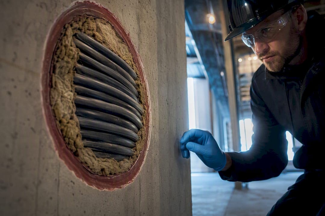
Firestopping for cables means installing a tested, UL-listed system that matches the wall or floor assembly, the cable type, and the annular space around every penetration, then documenting it before the ceiling closes. Every other decision on a project follows from that single requirement. Skip the listed-system match and generic “fire-rated” caulk, and you have not firestopped anything. You have created an inspection failure waiting to be discovered.
TL;DR:
- Only UL-listed, matched firestop systems that specify the assembly type, cable size, and annular gap are compliant and can withstand real fire and hose-stream tests.
- Proper installation requires precise measurement, backing placement, and seal application, with constant documentation and photographic evidence to pass inspection.
- Modular and removable systems like firestop pillows and transit frames perform better in dynamic environments such as telecom rooms with frequent cable changes.
- Fire-resistance ratings of cables, such as plenum or riser rated jackets, are independent of the firestop system and must also meet code requirements to prevent smoke and fire spread.
- Any change or addition to cabling after initial firestop installation demands re-verification, rework, or switching to rated solutions to maintain compliance and avoid liability.
What Is Firestopping for Cables, and Which Products Actually Work?
Cable firestopping refers to sealing openings where wiring passes through fire-rated walls, floors, or fire-resistant joints, using a system that has been tested and listed to restore that assembly’s fire resistance. The industry sometimes calls this cable penetration firestopping or, more broadly, passive fire protection. Whatever term shows up on a spec sheet, the underlying job is the same: stop fire, heat, and smoke from traveling through the hole your cables created.
Four product categories cover almost every cable penetration you will encounter, and each fits a different field condition.
- Preformed sleeves and transit frames. These modular systems use square or rectangular pathways instead of round conduit, which packs more cable per square inch and makes future adds easier without disturbing the seal.
- Intumescent caulk and putty. These expand under heat and work well for small annular gaps around individual conduits or a handful of cables, but they offer limited reconfigurability once cured.
- Firestop pillows and modular inserts. Removable by design, pillows are the standard choice for telecom rooms and data centers where cable counts change constantly.
- Cable transit systems, grout, and collars. For cable trays, bundled conduits, or large multi-cable openings, transit frames with insert modules or grout-based systems handle the higher fill volumes that sleeves and pillows cannot.
The common failure point across all four is the same: cable bundles are inherently leaky, and traditional methods that rely on exact reinstallation after every change tend to break down over time as STI Firestop points out. That is precisely why modular and removable systems have gained ground in any space where IT and cabling teams touch the infrastructure regularly. If your telecom room sees monthly moves and adds, a pillow system or transit frame will survive that churn far better than a one-shot caulk application.
The Codes and Standards Governing Firestopping in the United States
The 2021 International Building Code governs fire and smoke protection features in Chapter 7, and Sections 714 and 715 specifically address through-penetration firestop systems and fire-resistant joint systems. If your building falls under IBC 2021, these sections are the backbone of every firestop decision you make. Section 1705.18 layers on top of that, defining when a project requires special inspection of firestop installations by a qualified third party.
The National Electrical Code adds its own mandate. NEC Articles 300.21, 770.26, 800.26, and 820.26 require sealing openings around electrical and communications penetrations to prevent fire spread, covering everything from power circuits to coaxial and fiber runs.
Testing standards translate those code requirements into measurable performance:
- UL 1479 and ASTM E814 define the test method that produces F, T, and L ratings, and both require a hose-stream test to verify the seal survives thermal shock and water pressure after fire exposure.
- ASTM E2174 governs the on-site inspection procedure for installed firestop systems, giving inspectors a repeatable method rather than a visual guess.
Here is the detail contractors miss most often: a product labeled “fire-rated” on its packaging is not automatically compliant. It only satisfies code when it is installed as part of the specific tested and listed system for that exact assembly, penetrating item, and annular gap. As IAEI Magazine frames it, firestopping is an engineered system, and a seal that is “almost” right can still fail under real fire and hose-stream forces. A system that passes visual inspection but does not match a UL design number on paper is not a compliant installation. It is a liability with a fresh coat of caulk.
How to Choose the Right UL Listed System for Your Field Condition
Matching a listed system to a real penetration is not guesswork if you work through it in order.
- Identify the rated assembly and hourly rating. Pull the wall or floor assembly type from construction drawings and confirm the required fire-resistance rating, then start your search in the relevant UL G-series (floors) or A-series (walls) design drawings.
- Measure the penetrating items and annular space. Count and size every cable, conduit, or cable tray passing through the opening, and measure the actual gap between the penetrating items and the substrate.
- Calculate aggregate cable fill. Add up the total cross-sectional area of all cables and compare it against the maximum fill percentage the listing allows. Exceeding that limit voids the listing even if everything looks tidy.
- Locate a matching UL system listing. Search by assembly type, penetrating item category, and annular gap range until you find a design that matches your exact field condition, then confirm the required backing material and seal depth.
- Escalate when nothing matches. If no listed system fits, split the cable load across two smaller openings, switch to a rated cable transit system rated for higher fill, or request an engineering judgment from the manufacturer or a fire protection engineer.
Pro Tip: Keep a printed or PDF copy of the exact UL system drawing on-site during installation. Field crews who install from memory almost always drift from the listed annular gap or backing depth, and that drift is what fails inspection.
Coordinating this checklist against Division 07 firestop specs and your MEP drawings early avoids the classic “you poke it, you patch it” scramble that FCIA’s spec guidance warns against, where cabling crews cut new holes without telling anyone responsible for compartmentation.
Installing Cable Firestopping Correctly the First Time
Good installation starts before the sealant ever leaves the tube. Clean the substrate around the opening, measure the actual annular gap against the listing’s allowed range, and install backing material, typically mineral wool where the system calls for it, to the exact depth specified. Skipping backing or guessing at depth is one of the fastest ways to fail an inspection.
Cables need physical support independent of the firestop seal. Use J-hooks, cable tray, or bracket supports positioned so the cables cannot sag, shift, or pull on the seal during normal use or a fire event. A seal that has to bear mechanical load from unsupported cable weight was never designed for that job.
Apply sealant to the precise depth and configuration the listing specifies, not to whatever thickness looks sufficient. Field improvisation with off-the-shelf sealant is one of the most common reasons an otherwise reasonable-looking installation fails ASTM E2174 inspection.
Watch for these recurring failure modes:
- Overfilling an opening beyond the listing’s maximum cable fill percentage.
- Exceeding tested annular gap ranges by eyeballing instead of measuring.
- Concealing penetrations that were never identified, measured, or matched to a listing.
- Missing hose-stream-resistant components in systems that require them, which only shows up when the assembly is tested under fire and water pressure together.
Pro Tip: Photograph every penetration from at least two angles before backing material goes in and again after the seal is complete. Those two photo sets settle nearly every dispute that comes up months later during a retrofit or audit.
Documenting Firestop Inspections and Building a Penetration Register
Special inspection under IBC Section 1705.18 typically applies to fire-resistance-rated construction where a third-party inspector verifies that the installed condition matches the UL system listing on record, not just that something got sealed. Inspectors check annular gap, backing depth, cable fill, and sealant configuration against the listing drawing.
For every penetration, record:
- A unique penetration ID and its exact location.
- The UL design number used.
- Installer name and installation date.
- Photos taken before and after the seal.
- The allowed cable fill percentage and the actual fill at time of installation.
When a field condition doesn’t match the listing, you have three options: rework the installation to fit an existing listing, repair with additional backing or sealant to bring it into compliance, or replace the seal entirely with a different rated system. Documenting the UL design number, installer, and photos at close-up removes ambiguity later, which matters enormously during a retrofit five years down the line when nobody on-site remembers which system got installed. A well-kept as-built documentation record turns a stressful audit into a five-minute lookup.
Adding or Removing Cables Without Breaking the Fire Seal
Every cable move, add, or change at a firestopped penetration follows the same sequence.
- Survey before you touch anything. Confirm the existing system’s UL listing and its allowed cable fill before pushing a single new cable through a sealed opening.
- Follow the documented procedure if capacity allows. If the existing listing has room for the additional cables, follow the manufacturer’s reinstallation procedure exactly and update the penetration register with the new fill count and date.
- Stop and rework if capacity is exceeded or unknown. When the seal’s listing is undocumented, or the new cable load exceeds the tested fill limit, halt the work and arrange a new penetration, a rated transit system, or an engineered detail instead of forcing more cable through.
- Use retrofit-tested systems where you only have one-sided access. Midsummer Fire Protection’s retrofit guidance notes that single-sided tested systems solve the common occupied-building problem where the far side of a wall or floor is inaccessible during upgrades.
Cutting corners here is how a compliant building slowly accumulates undocumented penetrations that nobody can account for during the next audit.
How Cable Firestopping Actually Gets Coordinated in the Field
Cables and Chips builds firestop coordination into every structured cabling project that touches a rated assembly, because rework after the fact costs far more than getting it right during rough-in.
The pre-work survey comes first: confirm where compartment lines actually run, photograph existing conditions, measure every opening, and note the relevant UL G-series or A-series design references before any cable gets pulled.
Coordination only works when responsibility is assigned before work starts.
- Confirm who has authority to approve new penetrations in rated assemblies.
- Assign who installs the firestop system, whether that is the cabling crew or a dedicated firestop trade.
- Schedule inspection timing so close-up never happens before sign-off.
- Define what handover evidence, photos, UL numbers, fill data, gets delivered to the facilities team.
On every change, hold the ceiling or wall open until inspection is complete, capture before-and-after photos, and update the penetration register immediately. In telecom rooms especially, we favor removable pillow systems or modular transit systems over cured sealants, because they let a future crew add cable without cutting into a finished seal. That single choice, made once during design, saves months of friction later. Facility teams planning larger upgrades often pair this with a pre-project readiness checklist so the firestop conversation happens before the crew shows up, not after.
Why Cable Fire Performance Isn’t the Same as Firestop Performance
Firestop systems get all the attention, but the cables themselves carry their own fire performance characteristics that matter independently of the seal around them. Cable jacket material determines flammability, smoke density, and heat release when exposed to fire, and building codes address this separately from penetration firestopping through cable listing requirements like plenum-rated (CMP) or riser-rated (CMR) jackets.
A cable that generates dense smoke or propagates flame rapidly through a plenum space creates risk even in a building with perfectly executed firestop penetrations, because the danger isn’t confined to the wall or floor opening. It travels through the open plenum itself. That is why commercial buildings specify plenum-rated cable for above-ceiling and raised-floor runs, where air handling systems can carry smoke and flame gases throughout a floor in minutes.
Heat resistance matters too, particularly for life-safety and emergency communication circuits that need to keep functioning during a fire event rather than just avoid spreading it. This is a separate performance requirement from the T-rating on a firestop system, which measures temperature rise on the unexposed side of the wall or floor, not whether the cable inside keeps carrying signal.
The practical takeaway: a properly firestopped penetration with the wrong cable jacket rating still leaves a building exposed. Firestop compliance and cable jacket compliance are two different boxes that both need checking, and neither substitutes for the other.
Power Cables vs. Communication Cables: Different Firestop Considerations
Power and communication cables share the same UL-listed system framework, but the practical firestopping details diverge in ways that trip up crews who treat all cable penetrations the same.
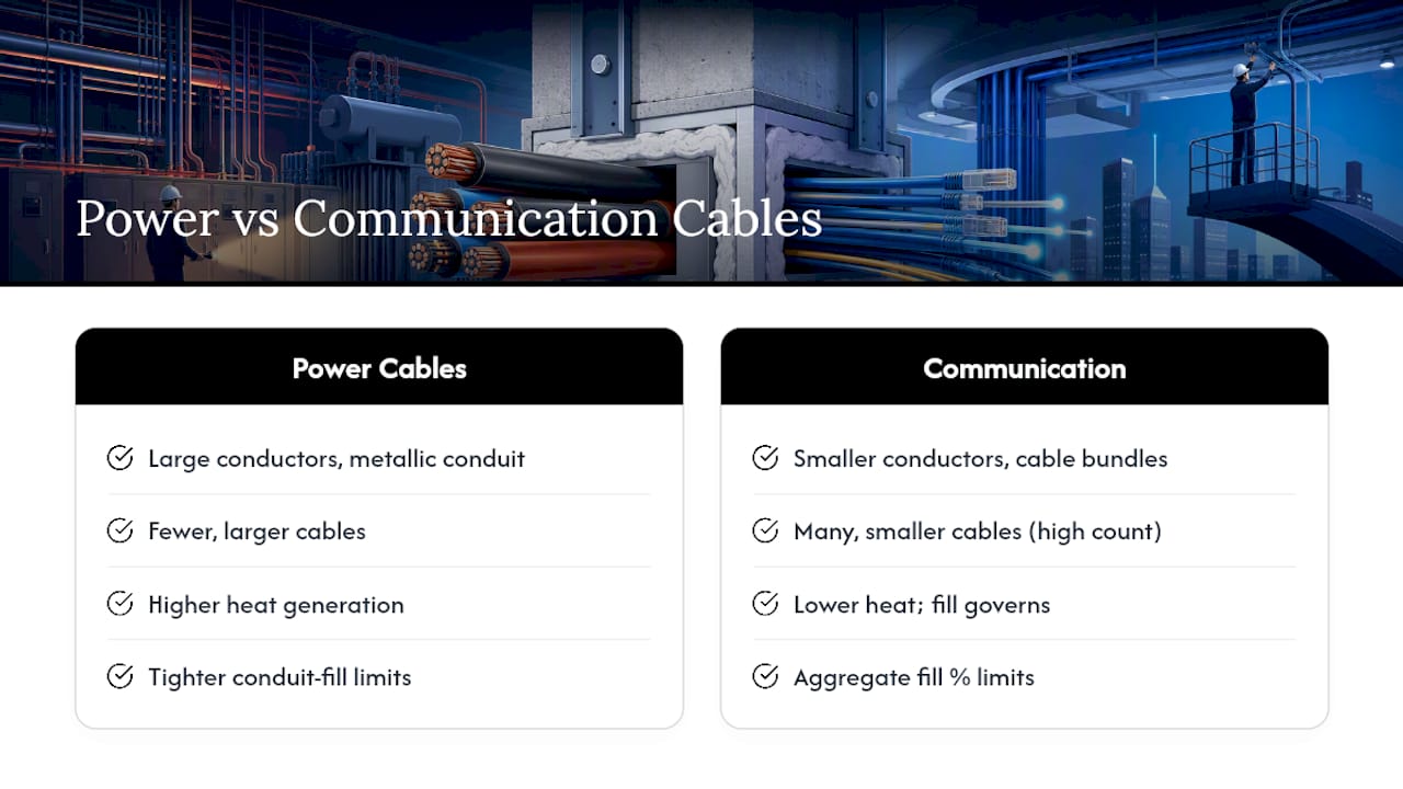
Power cable penetrations typically involve larger conductor sizes, metallic conduit, and higher heat generation under normal load, which affects annular gap calculations and sometimes requires higher-temperature backing materials near the seal. NEC Article 300.21 governs sealing requirements for these openings, and listings for power cable penetrations often specify tighter conduit fill limits because of the conductor bulk involved.
Communication cabling, covered separately under NEC Articles 770.26 (fiber), 800.26 (communications), and 820.26 (coaxial), tends to involve higher cable counts in a single opening but smaller individual cable diameters. This is where cable fill calculations become the deciding factor rather than heat generation. A telecom room penetration might carry two hundred CAT6A cables through one sleeve, and the aggregate cross-sectional area against the UL listing’s maximum fill percentage becomes the binding constraint, not the size of any single cable.
The other practical difference is reconfiguration frequency. Power circuits, once installed, rarely change. Communication cabling in an active office gets added to constantly as workstations move and equipment refreshes. That is the core reason modular pillow and transit systems dominate in telecom rooms specifically: the firestop system needs to tolerate a cabling contractor opening it every few months, something a cured caulk seal was never designed to survive.
Does Firestopping Affect Cable Signal Integrity or Performance?
Properly installed firestop materials have no measurable effect on the electrical or optical performance of cables passing through them. Intumescent caulk, mineral wool backing, and firestop pillows are non-conductive and don’t interfere with the twisted-pair balance, shielding, or optical transmission properties that determine signal quality.
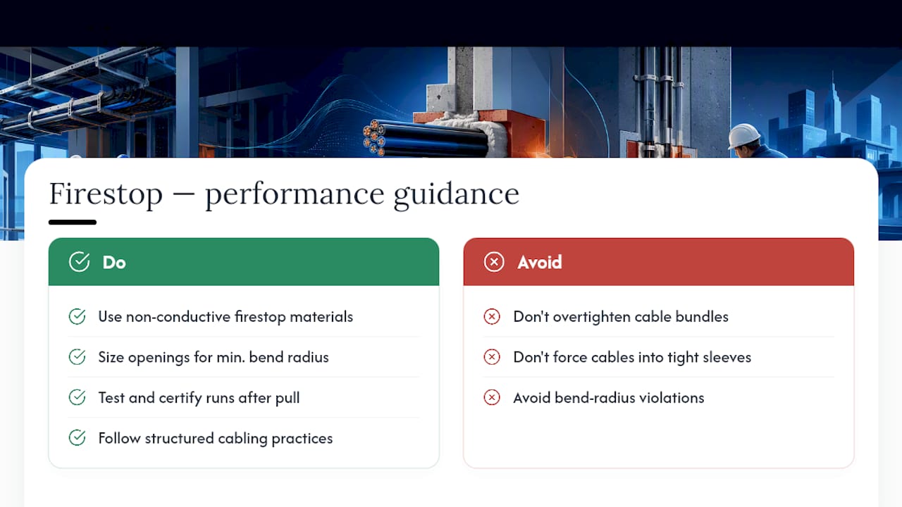
Where problems actually originate is physical installation error, not the firestop material itself. Overtightening a cable bundle while packing it through a sleeve can deform cable jackets and disrupt the twist ratio in copper cabling, degrading NEXT and return loss performance on a CAT6A run. Bend radius violations at a penetration point, where installers force cables into a tight sleeve opening, cause the same problem for both copper and fiber.
Fiber optic cables carry an added risk: excessive bending at a firestop penetration point can induce macrobending loss, reducing signal strength even when the fiber shows no visible damage. This is a reason to size sleeves and openings generously enough that cables maintain their minimum bend radius through the penetration, not just enough to satisfy the fill calculation.
The practical rule is straightforward: firestop material choice doesn’t compromise performance, but rushed installation through an undersized opening will. Any cabling contractor pulling cable through a firestopped penetration should test and certify the run afterward, the same way they would for any other segment, to confirm the penetration didn’t introduce a hidden performance problem. Projects that build in proper structured cabling installation practices from the start rarely see this issue at all.
Author Perspective: Why Discipline at the Penetration Beats Cleanup Later
The pattern across every firestop failure worth discussing is the same: someone treated a listed system as optional. Match the UL design to the assembly and cable configuration, document it before the seal disappears behind drywall, and re-firestop the moment anything changes. That is the whole discipline. It isn’t complicated, but it requires IT teams, facilities managers, and firestop specialists to coordinate before cable gets pulled, not after an inspector flags a mismatch. Projects that get this right start the conversation at the design phase. If you’re planning a cabling project that touches rated assemblies, Cables & Chips can help you coordinate that work correctly from the first site survey.
— Ken
Sources
- Firestopping: a point of reference between the National Electrical Code and the International Building Code — IAEI Magazine
- CHAPTER 7 FIRE AND SMOKE PROTECTION FEATURES – 2021 INTERNATIONAL BUILDING CODE (IBC)
- Firestop Inspection Requirements: IBC 2021 Special Inspection Guide | US Made Supply
FAQ
What Is the Difference Between Firestopping and Fireproofing?
Firestopping seals openings in fire-rated assemblies to maintain compartmentation, while fireproofing applies coatings or materials directly to structural elements like steel beams to protect them from heat. For additional fire safety measures, consider options like fire resistant metal filing cabinets that help protect important documents and equipment.
Can I Use Any Fire-Rated Caulk for Cable Penetrations?
No. A caulk labeled “fire-rated” only satisfies code when installed as part of the specific tested and listed UL system matching your assembly, penetrating item, and annular gap.
How Often Does Firestopping Need Special Inspection?
Special inspection under IBC 2021 Section 1705.18 applies to most fire-resistance-rated penetrations, with the requirement and inspector qualifications set by the authority having jurisdiction on each project.
What Happens if I Add Cables to an Existing Firestopped Opening?
You must confirm the existing system’s UL listing and fill capacity first; if the new cable count exceeds that limit, stop work and rework the opening with a rated solution instead of forcing more cable through.
Are Firestop Pillows as Effective as Caulk for Fire Resistance?
Yes, when the pillow system is part of a UL-listed design for that assembly and cable load, it provides equivalent fire resistance to caulk while remaining removable for future cable changes.