
Avoid Callbacks: IEC/TIA Fiber Termination Methods for Technicians
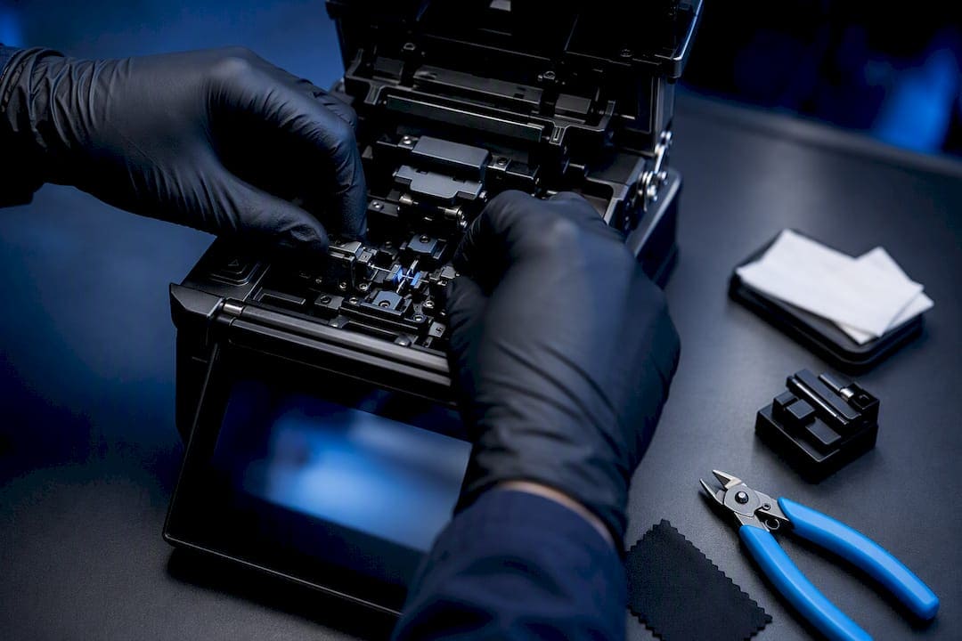
Fiber terminations are either connectors (dematable) or splices (permanent). Choose connectors for patching and cross-connects, and choose fusion splicing or splice-on connectors (SOCs) for singlemode permanent joints. Field-adhesive connectors work well on multimode and short-run singlemode when a technician has the skill and the polishing setup, but fusion splicing generally gives the lowest loss and remains standard for singlemode. Cleanliness, cleave quality, and documented acceptance testing decide whether a termination survives its first year in service.
TL;DR:
- Fusion splicing is the preferred method for long singlemode runs due to its lowest loss and reflectance, especially in outdoor or high-vibration environments.
- Epoxy and polish connectors deliver low loss but require skilled work and careful cleaning, making them less suitable for large or field deployments without proper training.
- Mechanical splicing and prepolished/splice connectors are faster options mainly used for emergency or temporary reconnects, but they usually have higher insertion loss than fusion splicing.
- Proper tool maintenance, including high-quality cleavers and thorough cleaning, significantly reduces rework and ensures termination reliability.
- Testing should include bidirectional insertion loss measurements and adherence to IEC and TIA standards for inspections, with cleaning and recleaving performed before considering termination failure.
Connectors vs splices: how to decide which one you need
A connector is a dematable interface, built so a technician can plug and unplug a fiber repeatedly without measurable loss. A splice is a permanent joint, either fused or mechanically held, meant to stay closed for the life of the cable plant. The FOA Reference for fiber optics frames the choice this way: both approaches must deliver low loss and mechanical strength, but they solve different problems.
Your decision usually comes down to five factors:
- Loss budget: tight optical budgets on long singlemode runs push you toward fusion splicing, which produces the lowest loss and reflectance of any termination method.
- Demateability: patch panels, cross-connects, and equipment ports need connectors; buried or aerial spans that will never be reopened are better served by splices.
- Permanence and environment: outdoor plant, direct burial, and underwater or high-vibration locations favor fusion splices protected in closures over exposed connector interfaces.
- Tool and skill availability: epoxy/polish work demands practice and a clean workspace, while SOCs and prepolished/splice connectors reduce the skill barrier for singlemode field work.
- Turnaround time: hot-melt and crimp connectors terminate faster than epoxy/polish, which matters on large multimode rollouts with tight schedules.
In practice, most jobs split cleanly by location. Data center and premise patching leans on factory-made or hot-melt connectors for speed. Premise multimode runs tolerate epoxy/polish or crimp terminations well. Outside-plant singlemode splices almost always go to fusion splicing, with SOCs or pigtails handling the field connectorization at each end.
Connector termination methods and how each one performs
Every connector method trades speed against loss performance and skill requirements. Here is how the common ones actually work in the field, along with what to expect once you put a test cord through them.
- Epoxy and polish. Strip the buffer, apply the correct epoxy (anaerobic, heat-cure, or UV-cure depending on the connector shell), inject it into the ferrule, insert the fiber, and cure per the adhesive’s schedule. After cure, scribe and cleave the fiber flush with the ferrule tip, then polish through a multi-step sequence (air polishing film, typically 12 micron down to 0.3 micron) until the end face passes inspection. Epoxy/polish connectors, done correctly, deliver consistently low loss across connector types, but the method is sensitive to rushed cure times or contaminated epoxy.
- Hot-melt. A pre-loaded adhesive stick inside the connector is heated in a small oven, the stripped fiber is inserted while the adhesive is molten, and it cools and hardens in minutes. Hot-melt connectors are fast and repeatable for multimode premise work but are less common on singlemode where loss margins are tighter.
- Anaerobic adhesive. Similar workflow to epoxy but cures at room temperature without heat, trading a slightly longer working window for the convenience of no oven. It suits field conditions where power for a curing oven is inconvenient.
- Crimp and cleave. No adhesive at all: the fiber is stripped, cleaved to a set length, inserted into a pre-polished ferrule until it seats against an internal stop, and a crimp sleeve locks the buffer and strength members in place. Watch for pistoning, where the fiber retreats slightly inside the ferrule under thermal cycling; a good crimp on both the fiber and the strength members prevents it. Crimp connectors terminate in under a minute once you have the technique down, which is why they dominate rapid multimode deployments.
- Prepolished/splice connectors and SOCs. These convert a termination into a splice. You cleave the fiber to a precise length, insert it into a connector that already has a short factory-polished fiber stub inside, and either crimp a mechanical splice element or fuse the two fiber ends together inside the connector housing. The FOA notes that prepolished/splice connectors and SOCs are especially valuable for singlemode field terminations, since they remove the polishing skill barrier entirely and shift the accuracy burden onto the cleave.
Expected insertion loss varies by method and connector type, but epoxy/polish and fusion-based SOCs tend to land at the low end of any manufacturer’s stated range, while crimp and hot-melt connectors run slightly higher on average due to the mechanical tolerance stack. Troubleshooting almost always starts the same way regardless of method: a dirty or scratched end face causes most high-loss failures, not a bad adhesive batch or a bad crimp.
Pro Tip: Keep a dedicated, labeled cure timer for every adhesive type you stock; guessing at cure time is the single fastest way to turn a good epoxy termination into a rework.
Fusion vs mechanical splicing: setup, process, and best practices
Fusion splicing fuses two fiber ends together using an electric arc, producing a joint with typically the lowest loss and reflectance available in fiber work. The process starts with stripping the buffer coating, cleaning the bare fiber with an approved wipe, and cleaving to the splicer manufacturer’s angle tolerance, usually under 0.5 degrees. Corning’s application note AN103 describes three common alignment technologies used inside fusion splicers: core alignment, which images the actual core position and gives the best results on singlemode; profile alignment, which uses the fiber’s outer profile as a proxy; and passive V-groove alignment, which is faster but more dependent on cleave quality. Once fused, the splice is protected in a heat-shrink sleeve run through a small oven built into the splicer, which reinforces the bare joint mechanically.
Mechanical splicing skips the fusion step entirely. The two fiber ends are aligned inside a V-groove, capillary tube, or elastomeric holder and held together with an index-matching gel that reduces the light loss across the physical gap. It is faster to execute in the field and needs no electricity, which makes it useful for emergency restoration or temporary test connections, but it typically shows higher loss and higher reflectance than a fusion splice. The FOA’s mechanical splice notes point out that you can sometimes improve a marginal mechanical splice by slightly withdrawing or rotating one fiber while watching a visual fault locator, minimizing visible light leakage before final clamping.
A few practices separate a clean splice job from a shop full of rework:
- Verify your cleaver’s angle and length settings against the splicer manufacturer’s tolerance before starting a batch, not after the first bad splice.
- Clean gloves, clean wipes, and a closed splice tray lid between splices keep airborne contamination out of the fusion chamber.
- On ribbon or mass fusion jobs, confirm the ribbon fiber count and splicer program match before firing the arc; a mismatched program produces uneven splice loss across the ribbon.
- Log splice loss estimates from the splicer’s own display for every joint, since a running record catches a drifting electrode or dirty V-groove before it fails an entire cable run.
Expect fusion splice loss to be lower than mechanical splices when using a well-maintained machine; mechanical splices usually have higher loss. Maintenance of fusion splicer electrodes is important to maintain low loss performance.
Tools that decide whether your termination yields hold up
Termination quality starts before you ever touch a connector or splicer. Your cleaver, stripper, cleaning supplies, and inspection scope determine whether the rest of the process even has a chance.
- Cleaver quality: a precision cleaver holding sub-degree angle tolerance is the difference between a clean, mirror-flat end face and a hackled or lipped one that no amount of polishing will fix. Corning’s guidance notes that investing in a high-quality cleaver pays back quickly through improved splice yields and fewer reworks.
- Inspection scope: a 200x to 400x fiberscope lets you check for chips at the core, residual contamination, and epoxy rings around the ferrule bore before you ever mate a connector.
- Cleaning technique: the FOA’s cleaning guidance recommends wet/dry cleaning with approved solvents, along with probe or cassette cleaners for recessed ferrules, and explicitly warns against canned air, which can leave propellant residue that causes cross-contamination on the next connector you touch.
- Reference cables and test jumpers: protect them like test equipment, since a scratched reference cord will quietly inflate every loss reading you take for the rest of the day.
Pro Tip: Never use building compressed air on an end face; it carries oil and moisture that canned air and approved cleaners are specifically formulated to avoid.
Protecting terminations and splices after they are made
A perfect splice or connector is only as good as the hardware protecting it afterward. Splice trays organize and protect individual fusion or mechanical splices inside a closure, keeping bend radius controlled and each fiber accessible for future work. Splice closures seal that tray assembly against moisture and physical damage in outside-plant or below-grade environments, while patch panels give connectorized fiber a stable, labeled home inside a rack or wall-mount enclosure.
- Use breakout kits when terminating loose-tube cable, since they convert bare buffer tubes into individually jacketed, connector-ready legs without exposing unprotected fiber.
- Maintain proper strain relief and bend radius at every entry point; a fiber pinched or bent below its minimum radius will show elevated loss long before it visibly fails.
- Ground armored outside-plant cable at the closure per local code, and always leave a slack loop, typically a full service loop of cable, so a future splice or repair does not require pulling new fiber.
- Label every connector, splice tray, and panel port at the time of installation. A structured cabling system’s documented components only stay useful if labeling and as-built records are current the day work finishes, not months later.
Testing and acceptance: what to run and what counts as a pass
Insertion loss testing with an optical loss test set (OLTS) tells you whether a link meets its budget; an OTDR trace tells you where along that link a problem sits and what is causing it. Run insertion loss testing for acceptance on every link, and reserve OTDR testing for troubleshooting, characterizing splice points, or verifying outside-plant spans where a fault could be anywhere along a long run.
- Test bidirectionally and average the results in both directions, since OTDR measurements carry a directional bias that a single-direction trace will not reveal on its own.
- Check return loss or reflectance alongside insertion loss, since a high-reflectance event usually points to a poor end-face polish, a dirty connector, or an air gap at a mechanical splice.
- Cite recognized TIA standards and manufacturer specifications as your acceptance baseline, and document every test result against that baseline rather than a rule of thumb.
- Reference IEC connector inspection guidance such as IEC 61300-3-35 when setting pass/fail criteria for end-face contamination and defects, since it gives you a defensible baseline that a client’s QA team will recognize.
IEC and Telcordia inspection documents provide the baseline procedures most acceptance testing is built on, but the same guidance is explicit that standards represent a minimum, not a guarantee, and that field cleaning still requires situational judgment beyond the standard test soils used to write those procedures.
Diagnosing failed terminations and deciding whether to reterminate
Most field failures trace back to one of four symptoms, and each one points to a specific fix.
- High, steady insertion loss usually means a contaminated or poorly polished end face; clean and reinspect before touching anything else.
- Intermittent loss that changes when you flex the cable points to pistoning or a loose crimp; reterminate rather than trying to reseat the existing connector.
- High reflectance on an OTDR trace signals an air gap, a bad cleave angle, or a dirty mechanical splice; recleave and resplice rather than reusing the same fiber ends.
- A splice or connector that fails retest after cleaning has likely suffered a cleave defect below the surface; recleaving costs a few minutes, so try it before condemning the fiber.
When a connector has failed twice after proper cleaning and recleaving, replacing it outright is faster and more reliable than continuing to chase the same fault.
What field experience teaches about singlemode terminations
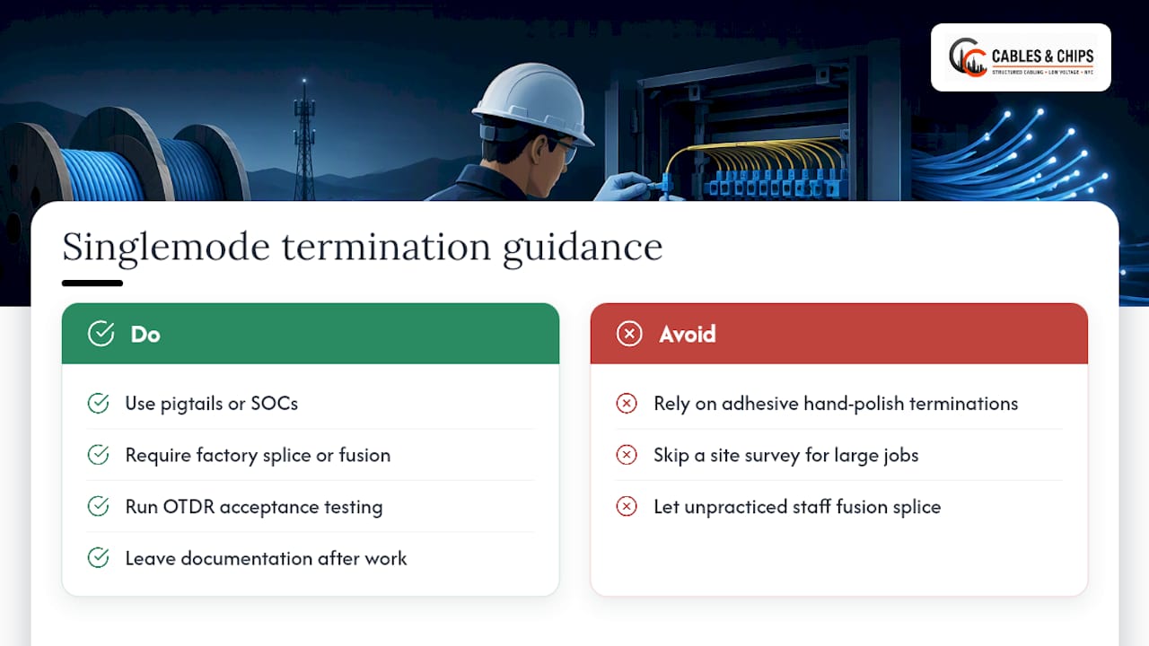
Experienced low voltage contractors who serve commercial and secure facilities across New York City note that singlemode field terminations done by adhesive and hand polish are often the most common source of callback tickets. Pigtails and SOCs remove most of that risk by shifting the accuracy burden onto a controlled factory splice or fusion joint rather than a hand-polished end face. If your team is not fusion splicing daily, a site survey before a large singlemode job is worth the time; our fiber installation team handles termination, splicing, and OTDR acceptance testing directly, with documentation left behind for your records.
Why standards compliance is a cost decision, not a checkbox
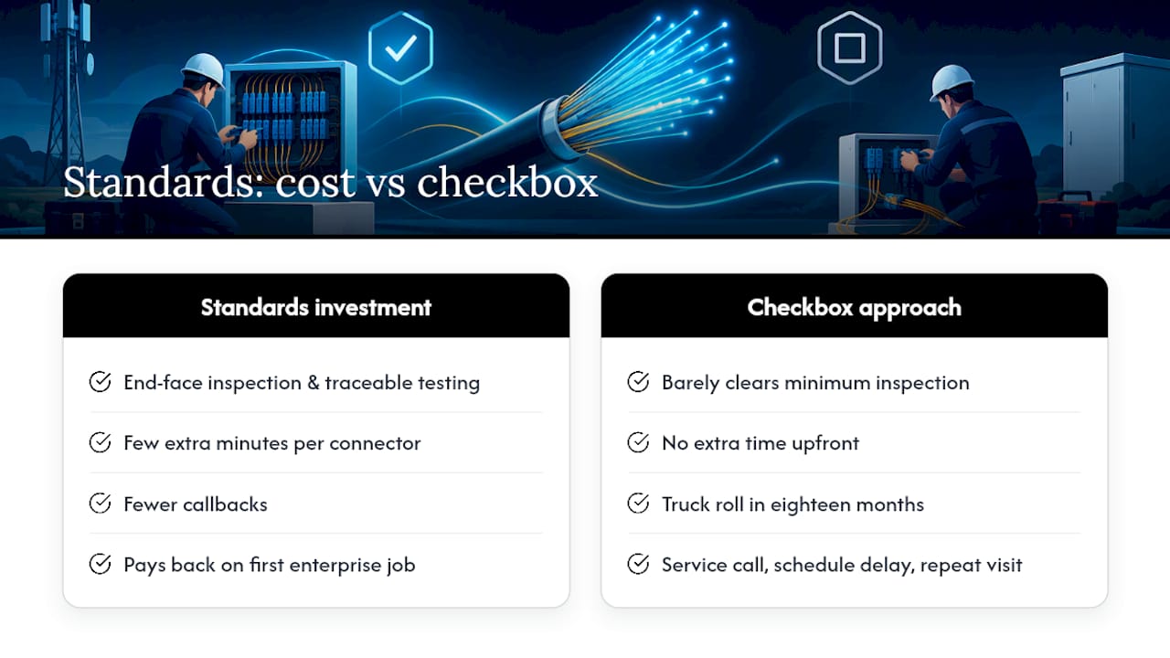
Treating IEC and TIA standards as the finish line, rather than the floor, is the most expensive habit in fiber work. A termination that barely clears a minimum inspection standard on day one is the one that generates a truck roll in eighteen months. Traceable acceptance testing and consistent end-face inspection cost a technician a few extra minutes per connector; skipping them costs a client a service call, a schedule delay, and a repeat visit to reopen a closure that should never have needed reopening.
The tool and training investment behind a clean cleave and a documented test result pays back on the first enterprise job that does not come back with a trouble ticket. That is the actual return on standards compliance, and it shows up in fewer callbacks rather than in the standard itself.
— Ken
Get professional fiber termination and testing support
Professional contractors handle fiber termination, fusion splicing, OTDR and insertion-loss acceptance testing, and full as-built documentation for commercial and secure facilities in New York City.

Our site survey process is free and no-obligation, and it moves faster when you have your fiber count, cable type (singlemode or multimode), and target locations ready ahead of time.
- Structured termination and fusion splicing for new or expanded fiber runs
- OTDR and insertion-loss acceptance testing with documented results
- MDF/IDF cleanup and network closet organization tied to your fiber plant
- As-built documentation and labeling delivered at project close
Request a site survey through our fiber installation page and we will scope the work before you commit to anything.
Sources
- The FOA Reference For Fiber Optics – Termination
- Cleaning fiber optic connectors (FOA)
- Easier fiber end-face inspection (Fluke Networks blog)
FAQ
Is it hard to terminate fiber?
Crimp and hot-melt connectors are approachable for a beginner within a few practice runs, while epoxy/polish and fusion splicing take real repetition to master consistently. Prepolished/splice connectors and SOCs narrow that gap for singlemode work by removing the hand-polishing step entirely.
How much does it cost to terminate fiber?
Cost depends on connector type, fiber count, and whether the job needs fusion splicing equipment or basic crimp tools, so there is no single field-wide figure to quote. For a project-specific quote, Cables & Chips offers a free, no-obligation site survey to price out termination and testing work.
What are the different methods of cable termination?
The main connector methods are epoxy/polish, hot-melt, anaerobic adhesive, crimp/cleave, and prepolished/splice connectors or SOCs, while splicing is done by fusion or mechanical means. Connectors are dematable and suit patching, while splices are permanent and suit outside-plant singlemode runs, according to the FOA Reference for fiber optics.
How do I re-terminate fiber optic cable?
Cut back past the damaged section, strip and clean the fiber, cleave to spec, and either reinsert into a new connector or re-splice depending on the original method. Always reinspect the end face and retest insertion loss before returning the link to service, since a repeat failure after cleaning usually means the fiber needs to be recleaved rather than reseated.