
Stop 2 AM Truck Rolls: Fiber Polarity, 4 MPO Methods and Field Checks
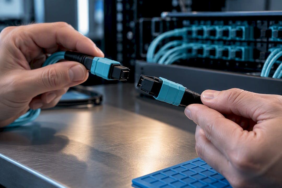
Fiber polarity means the transmit fiber (Tx) at one end of a link connects to the receive fiber (Rx) at the other end. Get that mapping wrong and the link fails or performs erratically even though every fiber tests clean for loss and continuity. The rule is simple for two-fiber duplex links. It gets genuinely complicated once you move to MPO/MTP arrays, where twelve or more fibers must map correctly across trunks, cassettes, and patch cords at once.
TL;DR:
- Failure to consistently apply a single MPO polarity method across all trunks and patch cords leads to common dead links or malfunctioning parallel optics systems.
- Using the incorrect MPO polarity method, such as mixing Method A and Method B, or neglecting to label trunks and patch cords correctly, is the primary cause of deployment errors in fiber networks.
- Fiber connector polish type (APC or UPC) and gender (male or female) are unrelated to polarity but must be matched properly to avoid insertion loss or connector damage.
- Field verification tools like visual fault locators and multi-fiber testers can quickly confirm proper fiber polarity and prevent costly troubleshooting later.
- Planning and documenting a consistent polarity scheme before installation and maintaining accurate records can prevent future rework and ensure reliable fiber network operation.
What Is Fiber Polarity and Why Duplex Links Still Trip Up Installers
A duplex fiber channel carries two strands: one for transmit, one for receive. The optical transceiver on Fiber A sends light out its Tx port expecting it to land on the far transceiver’s Rx port, and vice versa on Fiber B. If both ends map straight through without a crossover somewhere in the channel, Tx meets Tx and Rx meets Rx, and the link never comes up.
Two design patterns solve this. The first uses a crossed (A-B) permanent backbone with straight-through patch cords at both ends, so the flip happens once, in the cable plant, out of sight. The second keeps the permanent backbone straight and puts a crossover patch cord at one end only. TIA-568 guidance favors picking one crossover location and sticking to it across the facility, rather than mixing both patterns in the same building.
Consistency is what saves you on a 2 a.m. troubleshooting call… A few habits make Tx/Rx mismatches easy to spot before they become service tickets:
- Standardize on one crossover location (backbone or patch cord) for the entire site, not per closet.
- Label both ends of every duplex run with the same designation the day it’s pulled.
- Check link lights first. A duplex fiber link with no light usually means one thing: reversed Tx/Rx.
- Swap the two strands at one end, not both, when you suspect a polarity fault. Swapping both just reverses the same mistake.
Duplex polarity is the easy case. Array-based fiber changes the math entirely.
MPO Polarity Methods A, B, C, and U1/U2 Compared
MPO connectors pack up to 24 fibers into a single push-pull ferrule, and every fiber occupies a numbered position (1 through 12, or 1 through 8) that must land on the correct position at the far end. Positions are read from the key, the small ridge on top of the connector that also determines orientation. Key-up and key-down orientation, combined with male (pinned) and female (unpinned) connector gender, is what lets an MPO array carry polarity information the way a single fiber pair can’t.
TIA-568 defines three base methods, plus two newer universal variants, and picking the wrong one for your application is the single most common cause of dead parallel-optics links on day one.
- Method A uses a straight-through Type A trunk (key up to key down, position 1 stays position 1). The flip happens in the patch cords: one end of the channel needs a standard patch cord, the other needs a crossover patch cord. Miss that detail during a move or add, and you’ve built a broken link that tests fine on a simple continuity check.
- Method B uses a Type B trunk, where the entire fiber array reverses end to end (position 1 becomes position 12). Because the reversal lives inside the trunk, both ends use identical standard patch cords. That symmetry is why Method B is the common recommendation for 40G and 100G parallel optics, where consistent hardware at both ends matters more than in simple duplex breakouts. A modified version of Method B accommodates APC-polished connectors, which can’t physically key the same way as UPC.
- Method C flips fiber pairs (1↔2, 3↔4) rather than the whole array. It works fine for duplex breakout applications built from an MPO trunk, but it actively works against you in parallel optics, where the transceiver expects a full-array reversal, not a pairwise swap.
- U1/U2 universal methods use non-pinned connectors on both trunk ends, letting the same trunk serve as either Method A or Method B depending on which patch cords you attach. That flexibility is valuable if you expect to migrate from 10G duplex to 40G or 100G parallel optics later, since you avoid re-pulling backbone cable when the electronics change.
The most common field failure isn’t picking the wrong method; it’s mixing methods within the same building, or landing a Type B trunk on a cassette that was labeled for Method A. Audit the cassette and trunk labels together, every time, before you trust a build sheet from a previous phase.
Color Codes, APC vs. UPC, and Connector Rules That Aren’t About Polarity
Connector color has nothing to do with Tx/Rx mapping, but confusing color coding with polarity is a common and costly mistake. Color signals fiber type and polish, full stop.
| Color | What it indicates |
|---|---|
| Blue | Single-mode, UPC polish |
| Green | Single-mode, APC polish |
| Beige | Multimode OM1 |
| Aqua | Multimode OM3/OM4 (laser-optimized) |
The polish distinction matters more than most technicians expect. APC (angled physical contact) connectors have an 8-degree angled end-face designed to minimize back reflection, while UPC (ultra physical contact) end-faces are flat. Mating an APC connector into a UPC adapter, or the reverse, causes significant insertion loss and sometimes physical damage, because the angled ferrule doesn’t seat correctly against a flat one. The angled geometry also constrains key orientation on APC-polished MPO connectors, which is exactly why the modified Method B variant exists.
MPO gender adds another failure point. Equipment ports on transceivers are almost always male, with exposed guide pins, so the patch cord that connects to that port should be female. Plugging a male patch cord into a male equipment port bends or snaps the pins before you ever get to test polarity.
Before mating any connector, run this quick check:
- Inspect the end-face under a fiber scope for scratches, dirt, or pit damage.
- Confirm color and polish match what the port expects.
- Confirm gender: female patch cord to male equipment port, always.
- Confirm key orientation (up or down) matches the adapter.
Pro Tip: Keep a small stock of APC-to-UPC hybrid patch cords labeled and physically separated from your standard UPC stock. Techs grab the nearest cord under pressure, and a mislabeled bin is how mismatched polish ends up in a live rack.
How to Verify Fiber Polarity in the Field
Confirming polarity isn’t a guess, and it shouldn’t take longer than a standard loss test once you have the right sequence down.
Before touching a tester, do the groundwork: label both endpoints of the run you’re checking, isolate the channel from any active equipment, and record which method (A, B, or C) the build sheet says this run should use. Skipping this step is how techs end up “fixing” a polarity issue that was actually a labeling error two panels back.
- Identify the live side with a visual fault locator (VFL) or a live fiber detector. Injecting visible red light at one end and confirming which fiber lights up at the far end tells you immediately whether Tx and Rx are crossed.
- Map fiber positions across every panel the channel passes through, cassette by cassette, trunk by trunk. A single mislabeled cassette in an intermediate closet will defeat an otherwise correct end-to-end design.
- Confirm with a multi-fiber loss tester or MPO polarity tester. These tools test all twelve fibers in one shot and report both loss and position mapping, which is far faster and more reliable than checking strand by strand.
- Document the result against the build sheet: method used, trunk type, patch cord type at each end, and pass/fail per fiber. Acceptance testing should always include a polarity check, not just insertion loss.
If a channel fails polarity, you have three remediation paths, in order of how much disruption they cause: swap the patch cord at one end for the correct type (fastest), flip the cassette orientation in the panel (moderate), or use a field-configurable connector to change polarity without re-terminating anything. Field-configurable MTP connectors let you change polarity or gender on-site in minutes, which beats stocking four versions of every trunk length just in case.
Re-test after any fix, and update the label and port map immediately. An unfixed label is a problem you’re handing to the next technician who touches that closet.
Pro Tip: Carry a live fiber detector even on jobs you expect to be simple duplex runs. It answers the “which end is Tx” question in seconds, and it’s the fastest way to rule out polarity before you start chasing a phantom loss problem.

Choosing a Polarity Method Without Creating Future Headaches
Polarity decisions made during design outlive the person who made them, often by a decade. A few operational habits keep that decision from becoming a liability:
- Pick one polarity method for the entire facility (or at minimum, one per building phase) and write it into the design documents before the first trunk gets pulled.
- Limit the variety of trunk and patch cord types you stock. Every extra SKU is another chance for the wrong cord to end up in the wrong rack.
- Keep a small inventory of field-configurable MPO connectors or a polarity-change tool on hand, so a mismatch doesn’t stall a cutover while you wait on a special-order cord.
- Maintain as-built diagrams and port maps that show polarity method per run, not just fiber count. A future technician needs to know how it’s wired, not just how much.
- If parallel optics (40G, 100G, or beyond) are on the roadmap, favor Method B or a U1/U2 universal scheme now, even if the current gear is duplex. Re-pulling backbone cable later costs far more than planning for it up front.
Field Checklist: Common Polarity Traps We See on Commercial Installs
On commercial sites, the same three mistakes account for most polarity callbacks: mixed connector polish, the wrong patch cord type at a crossover point, and an undocumented cassette flip made during a prior move or add. A standard verification pass, in order, catches all three: label first, trace the run panel by panel, test with a multi-fiber tester, then document.
Reterminate only when the end-face itself is damaged. Replace jumpers when the type is simply wrong. Reach for a field-configurable connector when the fix needs to happen the same day, without a special order.

Why Polarity Planning Matters: A Field Perspective
Polarity mistakes rarely show up as a dramatic failure. They show up as a truck roll for a “bad fiber” that tests perfectly for loss, and a technician spending an hour tracing a mismatch that proper documentation would have caught in five minutes. Get the method chosen once, documented clearly, and verified at handoff, and most of that cost disappears before it starts.
— Ken
Get Your Fiber Infrastructure Verified by Cables and Chips
If the sections above made you want to double-check a closet you haven’t looked at since the last tenant fit-out, that instinct is worth acting on. Experienced network infrastructure contractors have spent decades building and troubleshooting commercial network infrastructure, and fiber polarity errors are exactly the kind of hidden problem that shows up as mystery downtime months after installation.

Our technicians handle fiber installation, termination, and testing with documented polarity verification built into acceptance testing, not treated as an afterthought. If you’re planning a fiber backbone upgrade, migrating to parallel optics, or you simply need existing runs tested and certified before you trust them, request a no-obligation site survey and get a clear picture of what’s actually in your walls and closets.
Sources
FAQ
How Do You Reverse Fiber Polarity?
You reverse polarity by swapping the transmit and receive fibers at one end only, either by using a crossover patch cord, flipping the cassette orientation, or using a field-configurable MPO connector. Never swap both ends, since that just recreates the original mismatch.
Can Fiber Optic Cable Be Run on Utility Poles?
Yes, fiber is commonly run on aerial utility poles, typically as armored or all-dielectric self-supporting cable rated for outdoor spans. Aerial runs don’t change polarity requirements. The same Tx-to-Rx mapping rules apply once the cable terminates indoors.
Are Fiber Optic Cables Directional?
Yes, in the sense that polarity requires transmit at one end to reach receive at the other. The glass fiber itself carries light in either direction, but the connectors, transceivers, and patch cord wiring establish a required Tx-to-Rx path for the link to function.
Are Fiber Optic Cables Always Green?
No, fiber cable and connector jackets vary by type and polish rather than following one universal color. Common conventions use blue for single-mode UPC, green for single-mode APC, aqua for OM3/OM4 multimode, and beige for OM1, according to standard color-code references.
What’s the Difference Between MPO Method A and Method B?
Method A uses a straight-through trunk and relies on a crossover patch cord at one end to establish polarity. Method B reverses the entire fiber array inside the trunk itself, letting both ends use identical standard patch cords, which is why it’s commonly recommended for parallel optics deployments.