
3 Fiber Polarity Types Technicians Must Recognize On Sight
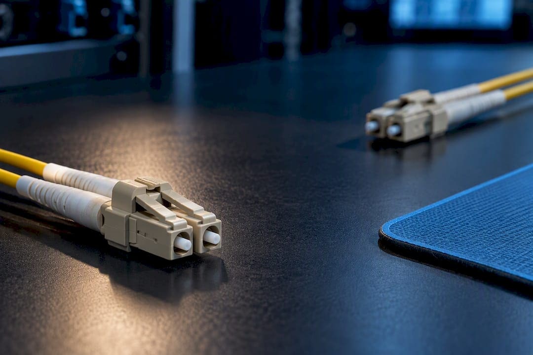
Fiber polarity comes down to three families technicians need to recognize on sight: duplex A-to-A/A-to-B patch cords, MPO Type A/B/C array methods, and the newer TIA U1/U2 universal mappings. Polarity simply means the transmit signal on one end lands on the matching receiver at the other end. Before touching a cross-connect or swapping a patch cord, run a continuity or MPO-capable polarity test to confirm what you actually have.
TL;DR:
- Correct fiber polarity relies on verifying patch cord type and array wiring method through testing before activation, especially when mixing A-to-A, A-to-B, or MPO types.
- Most issues stem from mismatched methods across installation phases or accidental connector rotations, which can be quickly diagnosed using visual fault locators or MPO testers.
- Standardizing on one polarity method and documenting it during design prevents confusion and reduces troubleshooting in complex hybrid or phased deployments.
- Mid-span connections and hold-up hardware must be verified for polarity compatibility, as added hardware can unintentionally alter the established polarity pathway.
- Incorrect polarity results in a dead link with zero signal, requiring precise testing and correction instead of assumptions, to avoid repetitive troubleshooting and ensure reliable network operation.
Duplex polarity basics: A-to-A vs A-to-B and practical wiring examples
Every duplex fiber link carries two strands: one for transmit, one for receive. Polarity fails when a Tx signal from one end arrives at another Tx port instead of the paired Rx. The fix depends entirely on the type of patch cord that sits between the equipment and the panel.
An A-to-A (straight-through) patch cord keeps position 1 at position 1 and position 2 at position 2 on both ends. An A-to-B (crossover) cord reverses those positions, so fiber 1 on one end lands on fiber 2 at the other. Most structured duplex links use one A-to-B connection somewhere in the channel, typically at the equipment cord or the horizontal cross-connect, so the Tx-to-Rx flip happens exactly once between endpoints.
On an LC duplex connector, the two ports are not labeled Tx and Rx directly. Instead, the transceiver itself marks its ports, and the technician’s job is to trace which fiber strand reaches which port at the far end. A quick visual check helps before you power anything on:
- Reversed pair: Both ends show A-to-A cords with no crossover anywhere in the link, so Tx never reaches Rx.
- Swapped plugs: A technician reseats a duplex LC connector rotated 180 degrees, silently flipping polarity at the panel.
- Missing crossover: A patch panel uses straight-through cords throughout, skipping the single required flip.
A-to-A cords are legitimate in legacy wiring schemes where the crossover already exists inside a preterminated backbone or a cassette. A-to-B remains the more common field cord because it is the simplest way to guarantee the single flip a duplex channel needs.
Array-based polarity (MPO/MTP): Type A, Type B, Type C and U1/U2 methods
Array connectors complicate polarity because a single MPO or MTP connector carries 8 or 12 fibers at once, and the mapping method determines how each fiber position on one end reaches its counterpart on the other.
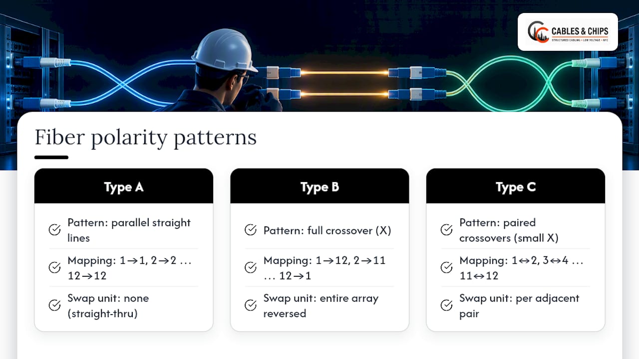
Type A trunks are straight-through: fiber 1 stays fiber 1, fiber 12 stays fiber 12, and the polarity flip happens instead through the orientation of the connector itself, pinned on one end and unpinned on the other. Type B trunks reverse the entire fiber sequence end to end, so fiber 1 on one connector lands on fiber 12 on the other, fiber 2 lands on fiber 11, and so on down the array. Type C trunks swap fibers in pairs rather than reversing the whole sequence, so fiber 1 swaps with fiber 2, fiber 3 swaps with fiber 4, while the overall connector orientation stays the same on both ends.
Base-8 systems, increasingly common for parallel optics at higher speeds, follow the same three logics but with four fiber pairs instead of six. The mapping math changes slightly, but the underlying method (straight, reversed, or paired swap) stays consistent with Base-12 practice.
The ANSI/TIA-568.3-E standard added two newer universal polarity methods, U1 and U2, specifically to simplify array-based duplex applications as networks move toward higher-speed parallel links. Rather than requiring a specific combination of trunk type, patch cord type, and cassette wiring to land correctly, U1 and U2 standardize the mapping so fewer components need to match perfectly for the link to work.
Identifying which method an existing installation uses takes some fieldwork:
- Check cassette labeling: Most MPO cassettes print their polarity type (A, B, or C) directly on the housing or a nearby label.
- Inspect key orientation: A pinned connector mated to an unpinned connector on the same trunk signals Type A; matched orientations on both ends suggest Type B or C.
- Trace a sample patch pattern: Light-test fiber 1 at one end and confirm which position it lands on at the other, then compare against the three known mapping patterns.
A 24-fiber MTP/MPO to LC cassette is a common example of how the array-to-duplex breakout absorbs part of the polarity flip internally, which is why the cassette’s wiring diagram matters as much as the trunk’s.
How to check and verify polarity in the field: tools and step-by-step procedures
Confirming polarity before a link goes live saves far more time than troubleshooting a dark port after the fact. A handful of tools cover nearly every field scenario.
A visual fault locator (VFL) injects visible red light into one fiber so you can trace it to the matching port at the far end, which is often enough to confirm duplex polarity in minutes. A light source and power meter pair measures actual signal loss once polarity is confirmed correct. Continuity testers serve the same tracing purpose as a VFL on shorter runs. An OTDR locates faults and breaks along a fiber run but is not the fastest tool for a pure polarity check. MPO-capable tier testers and fanout adapters let you verify every lane in an array connector at once rather than one strand at a time.
For a duplex link:
- Inject VFL light into the Tx strand at one end and confirm it appears at the Rx port, not the Tx port, at the far end.
- Repeat in the opposite direction to confirm the return path.
- Once tracing confirms correct polarity, run a power meter test to verify the link meets loss budgets.
For an MPO array path:
- Identify the cassette or harness mapping printed on the hardware before testing.
- Connect an MPO tester or fanout adapter to check each lane individually rather than assuming uniform polarity across all 8 or 12 fibers.
- Flag any failed lane and retest after reseating, since a single rotated connector can throw off an entire array.
Reach for the OTDR when a lane fails and you need to find a break or a bad splice along the run. A quick VFL trace is usually enough when the only question is whether Tx reaches Rx.
Pro Tip: Document every test result and keep a polarity map with the as-built records. The five minutes it takes to log a mapping saves hours the next time someone reopens that panel.
Common fixes and best practices for maintaining correct polarity
Most polarity problems have a fast fix once you know what is actually miswired. The mistake is guessing instead of tracing first.
When a duplex pair is reversed, swapping an A-to-A cord for an A-to-B cord (or the reverse) at one point in the channel corrects it without touching the backbone. A polarity flip adapter accomplishes the same thing without a full cord swap when the existing cord is otherwise fine. When an MPO cassette shows the wrong mapping for the installed trunk type, reconfiguring the cassette’s internal wiring, or replacing it outright, is usually faster than repatching every individual strand at the panel.
- Standardize on one method per site: Mixing Type A and Type B cassettes across the same building multiplies confusion for the next technician.
- Label everything: Mark trunk type, cassette polarity, and patch cord type directly on the hardware, not just in a binder.
- Color code where possible: Consistent jacket or boot colors for A-to-A versus A-to-B cords cut misidentification in low-light closets.
- Test after every change: A link that passed testing last month is not guaranteed to pass after any patch cord swap.
Pro Tip: Pick a single polarity method (Type A, B, C, or U1/U2) for an entire site during design, not per closet. A mixed-method building is where most repeat trouble tickets come from.
Polarity considerations for hold-up and mid-span fiber connections
Hold-up connections and mid-span splices introduce an extra mating point that can quietly undo polarity planning done everywhere else in the channel. Each additional connector or splice point is another opportunity for a fiber pair to land in the wrong position, particularly when a mid-span repair uses a different connector type or fiber count than the original run.
A mid-span mechanical splice or fusion splice generally preserves polarity as long as fiber positions are matched one-to-one during the splice. The risk grows when a technician introduces a hold-up cassette, breakout, or interconnect at the midpoint, because that hardware carries its own polarity logic that must match the rest of the channel rather than contradict it.
Before adding any mid-span connection, confirm whether the new hardware is Type A, Type B, or Type C, and whether it complements or duplicates the flip already built into the trunk. Two Type B components in series, for example, cancel each other out and effectively behave like a straight-through Type A path, which can catch a technician off guard if the documentation assumes otherwise.
Test the full channel after adding any mid-span connection rather than only testing the new segment in isolation. A hold-up point that measures fine on its own can still break end-to-end polarity once it is spliced into a longer channel with its own existing flip.
How to handle polarity in hybrid cabling environments mixing different fiber types
Hybrid environments, where OM3 and OM4 multimode coexist with single-mode runs, or where Base-8 trunks feed Base-12 cassettes, need polarity planning treated as its own design step rather than an afterthought.
Mixing fiber types does not change polarity logic directly. Method A, B, C, and U1/U2 are independent of whether the glass is single-mode or multimode. The real risk in hybrid environments is inconsistent method selection across segments installed at different times or by different contractors, especially when a building has grown in phases.
A common failure pattern: an original OM3 backbone uses Type B cassettes throughout, then a later OM4 or single-mode expansion introduces Type A hardware because that is what a different vendor stocked. The two segments may each test correctly in isolation, then fail once patched together into a single channel.
When mixing fiber types or vendor hardware, treat every new segment as an unknown until tested against the existing method. Standardizing on U1 or U2 mapping, where the ANSI/TIA-568.3-E standard’s newer methods apply, can reduce the coordination burden across a hybrid environment by making the duplex mapping less dependent on matching every upstream component exactly. Document the fiber type and polarity method at every termination point so a future technician does not have to reverse-engineer the mix from scratch.
Impact of incorrect polarity on network performance and diagnostics
Incorrect polarity does not degrade a signal gradually. It typically produces a dead link: no light detected, no link light, and no partial data throughput to hint at what went wrong.
That binary failure mode is actually useful for diagnosis. A link with high loss but correct polarity tends to show intermittent errors, retransmissions, or reduced throughput, while a polarity fault usually shows a flat “no signal” state on both ends. Technicians who confuse the two symptoms sometimes chase a loss budget problem, replacing connectors or reterminating ends, when the real issue is a Tx port pointed at another Tx port.
Misdiagnosed polarity faults waste time because the fix (tracing polarity, not measuring loss) is entirely different from a signal degradation fix. A power meter reading of essentially zero light, paired with a physically intact fiber confirmed by VFL, is a strong signal to check polarity before anything else.
In parallel optics and higher-speed array applications, polarity errors can be more subtle: a partial lane failure inside an otherwise working MPO trunk. This is where per-lane MPO testing matters more than a single continuity check, since a single flipped pair inside a 12-fiber array will not show up on a whole-link power test the same way it shows up on individual lane testing.
Common real-world polarity issues and troubleshooting case studies
The most frequent field issue is a rotated duplex connector: a technician reseats an LC duplex plug 180 degrees during a patch panel move, and the link that worked yesterday goes dark today with no other change to explain it. Tracing with a VFL from both ends usually isolates this within minutes.
A second common pattern involves mixed cassette types installed at different phases of a project. A building’s original MPO backbone uses Type B cassettes, and a contractor doing a later expansion installs Type A cassettes because that is what shipped with a new switch bundle. Both segments test fine independently, then fail once cross-connected, because the flips do not align.
A third pattern shows up in preterminated trunk deployments where the trunk’s key orientation (pinned versus unpinned) does not match what the cassette expects. This produces a fully dark array port even though every individual fiber is intact and undamaged, which can mislead a technician into suspecting a bad trunk when the trunk is actually fine and simply mismatched to its cassette.
In each of these cases, the fix follows the same pattern: trace polarity first with a VFL or MPO tester before assuming a physical fault, check labeling and cassette type against the trunk’s documented method, and correct the mismatch at the single point where it was introduced rather than repatching the entire run.
Guidelines for designing new fiber optic installations with correct polarity planning
Polarity planning belongs in the design phase, not as a field decision made by whichever technician happens to be pulling cable that day.
Choose one polarity method for the entire site before ordering hardware. Mixing Type A, B, and C cassettes across different closets in the same building is the single most common source of the repeat issues described above. Where the project supports higher-speed parallel optics, evaluate whether the newer U1/U2 methods from ANSI/TIA-568.3-E simplify the design compared to a traditional Type A or B approach.
Specify polarity method explicitly in project documents and bid specs, rather than assuming a contractor will default to an industry-standard choice. When comparing array-based MPO trunks against LC-based duplex links for a given deployment, the decision affects polarity complexity as much as it affects density and cost; a comparison of MPO and LC approaches is worth reviewing before committing to one architecture for an entire floor or building.
Build a labeling and documentation standard into the design package before installation starts, covering trunk type, cassette polarity, and patch cord type at every termination point. Require certified testing and as-built polarity maps as a deliverable, not an optional add-on, so the person maintaining the network years later has a real reference instead of guesswork.
Detailed explanation of fiber polarity diagrams with visual examples to aid understanding
Reading a polarity diagram correctly means tracking two things at once: the fiber position numbers and the connector orientation at each end. A typical Type A diagram shows fiber 1 through 12 (or 1 through 8 on Base-8) running straight across from one connector face to the other, with an arrow or shading convention showing one end pinned and the other unpinned.
A Type B diagram looks visually different: the fiber position numbers cross over completely, so a line drawn from fiber 1 on the left lands on fiber 12 on the right, and the whole array mirrors that pattern down the line. This full reversal is usually drawn as an X-shaped crossing pattern across the diagram rather than the parallel lines seen in a Type A drawing.
Type C diagrams show a narrower, paired crossing pattern: fiber 1 and fiber 2 swap with each other, fiber 3 and fiber 4 swap with each other, and so on, producing a series of small X shapes rather than one large crossover across the entire array.
Vendor white papers, including the FS.com guide to fiber polarity, commonly include these exact diagram styles alongside connector photos, which makes them a useful visual complement to the TIA standard’s written definitions. When a printed diagram is not available in the field, sketching the fiber count and drawing which position lands where at the far end, using the same straight, full-crossover, or paired-crossover shapes, is often enough to confirm which method an unlabeled trunk actually uses.
Field perspective on polarity work
Most polarity failures we see on commercial jobs trace back to mixed methods introduced across separate phases of the same building, not to a single bad component. A proper site survey and certified testing catch this before it becomes a dark port on turnover day. Experienced technicians have applied that discipline across many years of commercial low voltage work in New York City.
— Ken
Fixing polarity issues with professional fiber installation
Getting polarity right on paper is one thing. Getting it right across a real building, with multiple closets, multiple contractors, and cabling installed in phases, is where most projects actually run into trouble. Certified testing and documented, standardized wiring methods help ensure the polarity map matches what is actually in the walls on every fiber project.

Our services cover the full scope a polarity-correct installation needs:
- Fiber installation and termination: proper trunk selection, cassette configuration, and connector work matched to one polarity method across the site.
- MPO cassette and trunk deployment: Type A, B, C, or U1/U2 mapping specified and documented before installation begins.
- Certified testing and documentation: per-lane MPO verification, duplex polarity confirmation, and as-built polarity maps delivered with the project.
If you are planning a new fiber build or troubleshooting an existing one, our fiber installation and testing services start with a site survey so the polarity method gets decided once, correctly, instead of patched together closet by closet.
Sources
Field decisions should trace back to published standards rather than habit or a vendor’s default assumption.
Cite these standards directly in project specs and test acceptance criteria rather than paraphrasing them secondhand, since revision cycles occasionally shift terminology or add methods.
FAQ
What is the polarity of fiber cables?
Polarity is the alignment that ensures the transmit signal from one end of a fiber link reaches the receiver on the opposite end. Duplex links use A-to-A or A-to-B patch cords to manage this, while array-based MPO systems use Method A, B, or C as defined in ANSI/TIA-568.3-E.
What is OM1, OM2, OM3, and OM4?
OM1 through OM4 are multimode fiber grades, with each higher number generally supporting longer transmission distances and higher data rates than the one before it. They describe the fiber’s optical performance, not its polarity method, so any OM grade can be wired with A-to-A, A-to-B, or any MPO polarity type.
How to tell if a fiber cable is single mode or multimode?
Single-mode fiber typically has a yellow jacket, while multimode fiber commonly uses aqua (OM3/OM4) or orange (OM1/OM2) jackets, following TIA color coding conventions. Connector color can also help, since single-mode connectors are frequently blue while multimode connectors are often beige or aqua to match the cable jacket.
What are the different types of fiber connections?
Duplex connections (commonly LC or SC connectors) carry two fibers, one for transmit and one for receive, and rely on A-to-A or A-to-B patch cords for correct polarity. Array-based MPO or MTP connections carry 8 or 12 fibers in a single connector and use Method A, B, or C, or the newer U1/U2 mapping, to manage polarity across the whole array.
Why does incorrect fiber polarity cause a completely dead link instead of a weak signal?
Polarity errors point a transmit signal at another transmit port instead of the intended receiver, so no usable signal reaches the detector at all. This produces a flat no-light reading on a power meter, which is different from the intermittent errors typical of a high-loss but correctly wired link.