
Fiber Bend Radius: Minimums, Math and Innerduct Basics
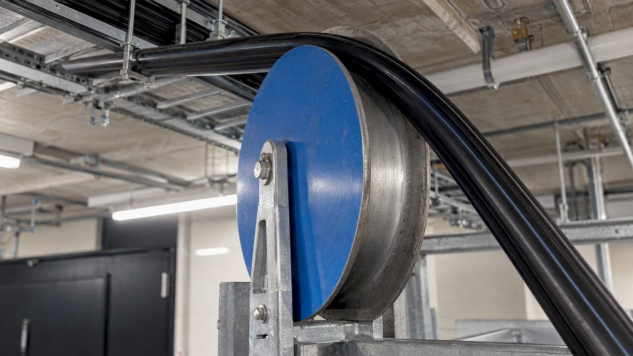
For most fiber optic cable, the minimum bend radius is 10 times the outer diameter (OD) of the cable once it is installed, and 20 times the OD while it is being pulled under tension. The cable manufacturer’s data sheet overrides any rule of thumb. Innerduct is how you hold those numbers in a real pathway: it gives the cable a smooth, continuous channel with controlled turns, and it leaves room for future pulls.
This guide covers the numbers, the arithmetic, what a tight bend does to a link, and how to size and place innerduct. It is written for IT directors, facilities teams and contractors who specify or inherit fiber in commercial buildings.
TL;DR
- The common rule is a minimum bend radius of 10× cable OD at rest and 20× OD under pulling tension. The manufacturer’s published figure always governs.
- To calculate it, multiply the cable’s OD by the factor. A 13 mm cable needs 260 mm (10 in) of radius under tension.
- Bends that are too tight cause signal loss, long-term fiber breaks and kinked buffer tubes. Bend-insensitive fiber reduces the risk but does not remove the need for planning.
- Innerduct subdivides a duct, protects the cable and preserves future capacity. Size it by fill ratio, and keep every sweep larger than the cable’s minimum radius.
- Document the pathway and test the finished link so the bend discipline can be verified.
What fiber bend radius means
Bend radius is the radius of the smallest circle a cable can be curled into without damage. A smaller number means a more flexible cable. Two details trip people up.
First, the radius is measured to the inside of the curve, not the centerline. Second, the number changes with the cable’s state. A cable being pulled is under tension and has less tolerance than the same cable resting in a tray.
The Fiber Optic Association (FOA) notes that bending a fiber optic cable at too small a radius can damage it, and that ignoring bend-radius guidelines can also void the manufacturer’s warranty. The FOA also stresses that installers need to know a cable’s pulling tension, minimum bend radius and crush load before the first pull.
CommScope names two reasons to protect the minimum radius in its white paper Fundamentals of Fiber Cable Management: long-term reliability and lower signal attenuation. A bend tighter than specified raises the odds of failure over time, because the stress on the glass keeps growing.
The minimums: a fiber bend radius chart you can use
There is no single universal figure. The values below come from manufacturer and industry documents. Read them as typical, then confirm the number on your own cable’s data sheet.
| Cable or source | During installation (under tension) | After installation (at rest) |
|---|---|---|
| General guidance from the FOA | 20× cable diameter | 10× cable diameter |
| Prysmian, loose tube and ribbon cable | 20× cable diameter | 10× cable diameter |
| Corning duct installation procedure, radius | 10× OD | 20× OD |
| ICC, inside plant cable, 2 or 4 fibers | 2 in | 1 in |
| ICC, indoor/outdoor cable up to 12 fibers | 20× OD | 10× OD |
The table looks inconsistent, and the reason matters. The Corning procedure defines both a minimum bend diameter and a minimum bend radius. It specifies a minimum bend diameter of 20× OD during installation and 40× OD afterward, which equals radii of 10× and 20× OD for outside plant duct cable. The same document raises the factors for cables above 216 fibers. Cable type, fiber count and construction all change the answer.
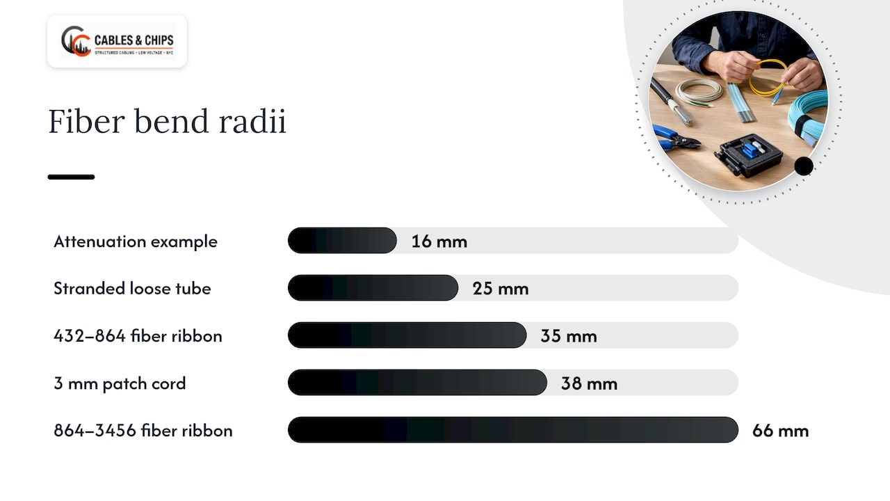
For tight-buffered indoor cable and patch cords, the figures are much smaller in absolute terms. CommScope’s white paper cites a Telcordia recommendation of a 38 mm minimum bend radius for 3 mm patch cords. It also notes that a bend with a 16 mm radius can produce up to 0.5 dB of attenuation.
Buffer tubes inside high-count cables have their own limits. Corning’s application note on buffer tube bend radius lists 25 mm for several stranded loose tube designs, 35 mm for 432 to 864 fiber ribbon cable and 66 mm for 864 to 3456 fiber ribbon cable. That matters when you open a splice enclosure or route tubes in a tray.
How to calculate the minimum bend radius
The formula is one line:
Minimum radius = cable OD × the factor for the cable’s state
Use the factor on the manufacturer’s data sheet. If none is published, the FOA’s default is 20× while pulling and 10× at rest.
Worked example: a 13 mm backbone cable
The FOA’s own example uses a cable 13 mm (0.5 in) in diameter. Under tension, the minimum radius is 20 × 13 mm = 260 mm (10 in). A pulley or sheave guiding that cable needs at least a 260 mm radius, or a 520 mm (20 in) diameter. At rest, the same cable can sit at 10 × 13 mm = 130 mm (5 in).
Worked example: a direct-buried cable
Corning’s direct-buried installation procedure works through a cable of 0.46 in (11.8 mm) diameter with a 15× factor. The minimum working radius is 15 × 0.46 in = 6.9 in (177 mm). Pull wheels and rollers need twice that as a diameter: 13.8 in (35.4 cm).
Radius or diameter: check before you cut a tray
Because some documents quote diameter and others quote radius, confirm the term before ordering a waterfall, a spool or a sweep fitting. Mixing them up produces a bend half as gentle as intended.
What happens when fiber bends too tightly
Corning’s note on buffer tube bend radius lists three outcomes from bends that are too small:
- Higher attenuation from macrobending. Light escapes the core at the bend, and the link loses signal.
- Fiber breaks or reduced long-term reliability. The glass can survive a tight bend for weeks and fail later.
- Kinked or permanently deformed buffer tubes. The cable’s internal geometry is changed for good.
Corning’s engineering note on bend performance explains the optics. When a bend passes a critical value, some of the light travelling at the core and cladding boundary can no longer be refracted back into the core. It is stripped out and shows up as insertion loss.
Wavelength matters too. According to CommScope, bending loss is greater at 1550 nm than at 1310 nm, and greater still at 1625 nm. A link that passes a test at one wavelength can show loss at another, so test at the wavelengths you will run.
Pulling is a separate risk. Prysmian states that pulling below the specified radius raises compression on the cable core, which can deform tubes and damage fiber or increase attenuation.
Bend-insensitive fiber: what it changes
Bend-insensitive fiber is designed to tolerate tighter curves. Corning’s note says that historically most fibers are optically unaffected by bends of 30 mm radius, and that its ClearCurve 50 micron fibers can be bent to a minimum radius of 7.5 mm.
The same note explains why this is valuable: inadvertent tight bends are common in high-density installations and in plants that are frequently reconfigured, and intentional tight bends are increasingly needed for smaller routing hardware and equipment cases.
Two practical points follow for an office build-out.
- A bend-insensitive fiber rating applies to the optical fiber under defined test conditions. Cable construction, buffer tubes and connectors still have mechanical limits, so keep using the cable’s published figure for pathway design.
- Tight patch fields in a crowded IDF are where the extra tolerance helps most. Even there, clean routing and proper managers keep the link easier to service.
For help deciding where fiber belongs in a building at all, see our fiber optic backbone office design guide and the CAT6A vs fiber optic decision guide.
Innerduct for fiber: what it is and when to use it
Innerduct is a flexible plastic subduct that runs inside a larger conduit or duct. Corning’s duct installation procedure says it subdivides the duct and provides for future cable pulls. It is available in ribbed, corrugated and smooth-walled polyethylene or PVC.
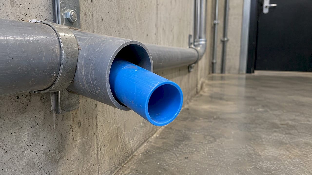
OFS explains why fiber is usually placed in small-diameter innerduct instead of loose in a large conduit: innerduct provides a clean, continuous path for installation. Its guidance adds that the right type depends on the environment (direct buried or in conduit) and the method (pulling or blowing), and that blown cable needs pressure-rated innerduct.
In practice, innerduct earns its place in four situations:
- Shared conduit. Corning notes that three 1.25 in inside-diameter innerducts can usually be pulled into a 4 in duct. Each tenant or system gets its own path.
- Future growth. An empty, capped innerduct is a ready route for the next cable, with no need to pull over an existing one. Corning advises that pulling a new cable over an existing one is not recommended because of possible entanglement.
- Long or exposed runs. Between buildings, through risers and under slab, the smooth interior lowers pulling friction and shields the cable.
- Visual separation. In a pathway crowded with copper, an identified innerduct makes the fiber easy to find and hard to damage during other trades’ work.
Choosing the type
Smooth-wall innerduct has the lowest friction, which helps with long pulls. Corrugated innerduct bends easily in short, tight spaces. OFS notes that corrugated innerduct is not recommended for direct-buried applications, and it recommends a minimum innerduct inside diameter of 1-1/2 in for direct burial. Match the product to the route, then confirm with the cable maker.
Sizing innerduct and conduit with fill ratio
Fill ratio is the share of the pathway’s cross-section occupied by cable. Corning’s guide to pulling fiber in conduit gives the formulas, with d as cable OD and D as conduit inside diameter:
- Single cable: fill ratio = d² / D²
- Multiple cables: fill ratio = (d1² + d2² + … + dn²) / D²
The same note gives recommended fill ratios: 65% for one cable, 31% for two cables and 40% for more than two. Corning points out that its 65% figure for a single cable is above the 53% figure in the National Electrical Code. Its reasoning rests on field testing of a cable in a conduit in good condition. Many designers use the lower code figure as the working limit, and that is the safer approach on a commercial job.
OFS gives a related rule for innerduct. Its optimal diameter ratio for pulling is under 75%, with an area ratio under 56%. For blown cable, the diameter ratio is 50 to 75% and the area ratio 25 to 56%.
A quick sizing example
Suppose you plan to pull one 13 mm cable through a 1.25 in (about 32 mm) innerduct. Fill by area is (13 × 13) / (32 × 32) = 169 / 1,024, or about 16.5%. That is well under every limit above. Adding a second 13 mm cable gives about 33%. That is near Corning’s 31% figure for two cables, so the second pull deserves a larger duct or its own innerduct. These are illustrative numbers. Real innerduct has a wall thickness, so use the actual inside diameter from the product data sheet.
Protecting bend radius in the pathway
Corning’s conduit guidance is direct: the radius of every conduit bend, cable guide, sheave and capstan must be greater than the cable’s minimum bend radius. That one sentence drives most field decisions.
Plan the route before the pull
- Read the data sheet. Write the installation and at-rest radius on the pull sheet.
- Check every turn. Conduit elbows, tray drops, riser offsets and rack entries all count. Use sweeps, not 90-degree fittings.
- Size the guides. Pulleys and rollers need at least twice the working radius as a diameter, as the FOA and Corning examples show.
- Leave slack with a plan. Where innerduct runs through a manhole, Corning calls for enough slack to secure it on racks while keeping the cable’s minimum radius. Cap or plug the innerduct after placement to keep out moisture and debris.
- Avoid reducing couplers. Where innerduct is not continuous, Corning says couplers that reduce the inside diameter should not be used.
- Manage the termination end. Cable managers, spools and slack trays in the MDF or IDF should hold the radius at rest. Do not let a door, cover or neighboring bundle push on the bend.
- Test and document. Certify the finished link and keep a record of the route and results.
The same discipline applies to copper. Our guide to Cat6 bend radius covers how to preserve it during installation. For a closet that has grown crowded, rack and closet cleanup is often the quickest way to remove tight bends, and our server rack setup checklist shows where slack and managers belong.
Common bend problems in commercial buildings
- Cable stuffed behind a door or cover plate in a tight IDF.
- Hook-and-loop or zip ties pulled so tight they deform the jacket and pinch the bend.
- Fiber lying across a sharp tray edge or over a conduit lip.
- Bundles of fiber compressed under heavy copper.
- Patch cords hanging unsupported from a high-density panel.
- Abandoned cable left in the pathway, which forces new fiber into awkward turns.
Each of these is a design or housekeeping issue, which is why bend radius belongs in the scope of work, not only in the installer’s habits.
Our perspective on fiber bend radius
Most bend-related fiber problems we see were not installed badly on day one. They built up over years of moves, adds and changes in a closet that nobody owned.
After more than 40 years working in commercial spaces in New York City, we treat bend radius as a pathway design question first and an installer skill second. Before a fiber is pulled, we check every turn on the route against the cable’s published minimum, size the innerduct for the first cable and the next one, and plan where slack will live in the MDF or IDF.
The finish matters as much as the pull. Clean, labeled, documented routing is what keeps a link serviceable when the next technician opens the rack. We test and certify the work so the owner has a record, not just a promise.
If you inherit fiber with tight bends, old abandoned cable or an overfull innerduct, a site survey is the right first step. We walk the route, measure what is there and tell you what needs to change.
Ken
Plan your fiber pathway with Cables & Chips
Cables & Chips designs, installs, terminates and tests fiber optic infrastructure for commercial offices, secure facilities and enterprise environments across New York City. We also handle abandoned cable removal and MDF and IDF cleanup, so the pathway is ready for new fiber.
See our fiber installation services in NYC or browse all of our low voltage services. We offer a no-obligation site survey. Schedule a Site Survey and we will review your routes, closets and pathway capacity.

FAQ
What is the minimum bend radius for fiber optic cable?
A common rule is 10× the cable’s outer diameter at rest and 20× during installation under tension. Some cable types and fiber counts use different factors, so follow the manufacturer’s published figure. Patch cords and tight-buffered indoor cable have much smaller absolute radii than outdoor loose tube cable.
How do I calculate fiber bend radius?
Multiply the cable’s OD by the factor for its state. A 13 mm cable under tension needs 20 × 13 mm = 260 mm (10 in). At rest, it needs 130 mm (5 in). Check whether the document you are using gives a radius or a diameter before you size any hardware.
Do I need innerduct for fiber in a building?
Not on every run, but it is the standard way to protect fiber in shared or long pathways. Innerduct subdivides the duct and provides for future cable pulls. Use it when fiber shares a conduit, when you expect more cable later, or when the route is exposed to other trades.
What size conduit or innerduct do I need for fiber?
Size it by fill ratio. For more than two cables, Corning recommends about 40%, and the National Electrical Code figure for a single cable is 53%, according to Corning’s conduit guidance. Every bend in the path must also be wider than the cable’s minimum radius.
Is bend-insensitive fiber immune to bend problems?
No. It tolerates tighter bends than standard fiber, with some Corning fibers rated to 7.5 mm, according to Corning’s engineering note. It is most useful in dense, frequently changed plants. Keep following the cable’s published limits when you design the pathway.
Sources
- Fiber Optic Association: Installing fiber optic cable
- CommScope: Fundamentals of fiber cable management
- Corning: Duct installation of fiber optic cable (SRP 005-011)
- Corning: Direct-buried installation of fiber optic cable (SRP 005-012)
- Corning: Buffer tube minimum bend radius (AEN001)
- Corning: Considerations for improved bend performance optical fibers (AEN110)
- Corning: Pulling fiber optic cable in conduit (AEN136)
- Prysmian: General optical fiber cable installation considerations
- ICC: Minimum bend radius and maximum pulling tension of fiber optic cables
- OFS: Placing fiber optic cable in underground plant (IP-009)