
100 Meters Is a Ceiling: Installer Rules from IEEE and TIA for Ethernet

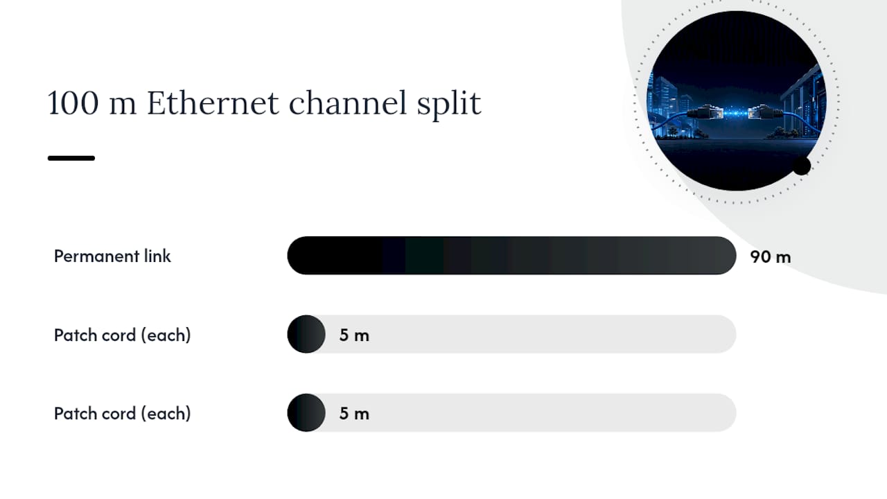
The industry-standard Ethernet distance limit is 100 meters (328 feet) for a complete channel, but the fixed cabling itself, called the permanent link, is only rated for 90 meters. The remaining 10 meters covers patch cords on each end. Real-world performance often falls short of that number once cable category, PoE load, temperature, and installation quality enter the picture, so treat 100 meters as a ceiling, not a target.
TL;DR:
- Real-world Ethernet performance often falls short of the 100 meter limit due to cable quality, PoE load, installation conditions, and testing tolerances.
- Cat6A cables reliably support 10 Gbps at 100 meters, making them the preferred choice for future-proof, high-speed commercial installations.
- Factors like crosstalk, poor terminations, cable heating, and conductor gauge can degrade performance and cause intermittent connectivity before reaching the 100 meter threshold.
- Power over Ethernet typically does not reduce maximum distance but introduces voltage drop concerns, especially for high-power devices over longer runs.
- Extending beyond 100 meters requires active solutions such as switches, fiber optic links, or Single Pair Ethernet, with fiber offering the most future-proof and reliable option for long distances.
What Is the Ethernet Distance Limit and Why 100 Meters?
The 100 meter figure isn’t arbitrary. It comes from decades of engineering work by the IEEE and the Telecommunications Industry Association (TIA) to define how far a signal can travel over twisted-pair copper before attenuation and timing errors make the connection unreliable.
A “channel” is the full electrical path between two pieces of active equipment: patch cord, wall jack, horizontal cable, patch panel, and another patch cord on the far end. The permanent link is the fixed part in the middle. It excludes the equipment cords and is capped at 90 meters, leaving up to 10 meters split between the two patch cords to complete the 100 meter channel. Cables and Chips builds every commercial installation around that 90/5/5 split, because it’s the buffer that keeps a finished job compliant even after a client adds a longer patch cord later.
The physics behind the limit comes down to three things: insertion loss (signal attenuation over distance), propagation delay, and crosstalk between the four twisted pairs inside the jacket. Push a cable too far and the receiving equipment can no longer distinguish the signal from noise, particularly at gigabit and 10-gigabit speeds where the electronics are working closer to their limits.
There’s also a measurement wrinkle worth understanding. Cable testers calculate length using the Nominal Velocity of Propagation (NVP), a setting that estimates how fast an electrical signal moves through that specific cable. NVP varies slightly by manufacturer and batch, and ANSI/TIA-1152 permits roughly a 10% uncertainty margin in length readings. That’s why a permanent link can sometimes test at 91 or 92 meters and still pass. It’s not a loophole, it’s tester tolerance, and no installer should intentionally design to that edge.
How Do Cat5e, Cat6, and Cat6A Compare for Distance?
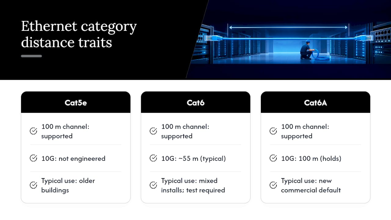
Every common Ethernet cable category, from Cat5e through Cat7, supports the same 100 meter channel limit at standard speeds. What changes is how much bandwidth you get to keep at that distance, and that’s where category choice actually matters.
Cat5e handles gigabit speeds to the full 100 meters reliably and remains common in older buildings, but it wasn’t engineered with 10 Gbps in mind. Cat6 supports 10 Gbps, but only up to about 55 meters in typical installations, dropping off after that because of alien crosstalk between adjacent cable bundles. Cables and Chips flags this constantly when clients assume Cat6 in the walls means 10G is guaranteed at full distance, it isn’t, and testing is the only way to confirm what a given run can actually carry.
Cat6A closes that gap. It’s built with tighter twists and better shielding to fight crosstalk, and it holds 10 Gbps across the full 100 meter channel. That’s why Cat6A has become the default spec for new commercial installs where 10G to the desktop or access point is even a possibility down the road, and it’s the category Cables and Chips installs as the practical standard for offices planning more than a few years ahead. Cat7 and Cat8 exist mainly for data center and short-run applications at higher frequencies. They don’t extend the 100 meter ceiling; they mostly add shielding and headroom for even higher speeds over shorter distances.
Vendor hardware adds another layer of nuance that pure cable specs don’t capture. Some Cisco 10GBASE-T transceiver configurations are documented to run reliably only to around 30 meters at full 10 Gbps, even though the same hardware supports 100 meters at 1 Gbps. The cable didn’t get shorter, the electronics inside the transceiver simply weren’t tuned for maximum copper reach at 10G. Always check the specific module or switch datasheet before assuming category rating alone tells you what a link can do.
Patch cords add one more variable. Field-terminated solid-conductor cable and factory-made stranded patch cords perform differently under bend and flex stress, which matters for Modular Plug Terminated Link (MPTL) and equipment-to-equipment (E2E) configurations increasingly used for cameras and wireless access points wired directly without a jack. Mixing cable types within a single channel is one of the more common ways installers accidentally introduce loss that doesn’t show up until the link is under load.
What Physical Factors Shorten Real-World Ethernet Range?
Attenuation increases with signal frequency, so higher speeds lose more strength per foot than lower ones. A cable that comfortably carries 100 Mbps for 100 meters may struggle to hold a clean 1 Gbps or 10 Gbps signal over the same run, simply because the electronics are pushing more information through the same copper at a higher frequency where loss is steeper.
Crosstalk and sloppy terminations do more damage in the field than distance alone. A poorly seated connector, an untwisted pair pulled too far back during termination, or a cable run parallel to a bundle of other Ethernet cables for too long can introduce near-end crosstalk (NEXT) that degrades performance well before the 100 meter mark. This is a common failure point found during retrofit projects: cabling that measures fine on a tape measure but fails a certification test because of a rushed termination years earlier.
Conductor gauge matters too. Standard Ethernet cable uses 23 or 24 AWG copper, and thinner gauge means higher DC resistance, which increases both signal attenuation and voltage drop for PoE devices. Temperature compounds the problem. Copper resistance rises as it heats up, and a bundle of cables running through a hot ceiling plenum or a sun-exposed conduit will show measurably worse insertion loss than the same cable in a climate-controlled space.
When a link is stretched too close to or past its practical limit, the failure modes are predictable:
- Packet loss and retransmissions that show up as sluggish file transfers or dropped VoIP calls.
- Automatic speed downshifts, where a gigabit port negotiates down to 100 Mbps because the link can’t hold a clean gigabit signal.
- Intermittent connectivity that appears under load or in certain temperatures but tests fine when idle.
- PoE devices that power on but behave erratically, browning out under load spikes.
None of these show up as a hard “cable disconnected” error, which is exactly why they’re so frustrating to diagnose without proper testing equipment.
Does PoE Reduce the Maximum Ethernet Distance?
Power over Ethernet doesn’t shorten the standard 100 meter channel limit, but it adds a second constraint that copper distance alone doesn’t capture: voltage drop. The farther power travels down a copper conductor, the more it’s lost to resistance, and that loss scales directly with both distance and conductor gauge.
A PoE camera or access point at 90 meters on 24 AWG cable will draw more voltage drop than the same device at 30 meters. For most 802.3af/at/bt PoE devices, that’s still within tolerance at the standard 100 meter maximum. But stack a marginal cable run, a hot ceiling space, and a power-hungry PTZ camera together, and you can end up with a device that boots, then browns out the moment it tries to move or trigger an IR illuminator. There are cases where a camera works fine on the bench but fails intermittently once installed at full cable length, precisely because voltage drop under real load was not accounted for.
Extended-distance PoE products exist, and they work by using thicker conductors, boosting voltage, or combining fiber with a copper power pair. These engineered solutions can push power well past 100 meters, but they are engineered workarounds, not standards-compliant 4-pair Ethernet PoE. TIA’s guidance on Class 2 power in smart buildings makes clear that once you exceed standard limits, you’re also stepping into different electrical code considerations (Class 2 versus Class 4 power), which can carry different documentation and safety requirements.
The conservative approach for PoE cameras, access points, and access-control readers: design to 90 meters of permanent link wherever possible, use Cat6A for anything power-hungry, and reach for a midspan injector or local power supply before you reach for a marginal 95-meter run. When distance genuinely can’t be avoided, a dedicated PoE distance planning approach that accounts for device wattage, cable gauge, and ambient temperature will save a callback.
How Can You Extend Ethernet Beyond 100 Meters?
Once a run needs to go past 100 meters, copper alone won’t get you there reliably. Several proven approaches exist, and the right one depends on budget, bandwidth needs, and how much power the far end requires.
Adding a switch as an active hop is the simplest fix. Placing an unmanaged or PoE switch at the 90 to 100 meter mark resets the signal and lets you run another full 100 meter segment from there. It’s inexpensive and easy to troubleshoot, but it adds a point of failure and, in a PoE setup, may require its own power source unless it’s PoE-powered itself.
Copper Ethernet extenders and repeaters use signal processing to stretch a usable connection to 500 meters or more over standard twisted pair, usually at reduced speeds like 10 or 100 Mbps. They’re a reasonable stopgap for a single device far from the closet, but they’re not a substitute for a properly designed backbone in a commercial building.
Media converters and fiber optic cable solve the distance problem outright. Fiber has no practical Ethernet-style 100 meter ceiling, single-mode fiber routinely runs kilometers, and it’s immune to the electromagnetic interference that plagues copper in industrial or electrically noisy environments. A media converter at each end bridges copper Ethernet to fiber and back, which is the standard approach for connecting buildings, floors, or any run where copper simply isn’t an option.
Single Pair Ethernet (SPE) offers a different tradeoff entirely. The IEEE 802.3cg standard (10BASE-T1L) supports runs up to 1,000 meters at 10 Mbps over a single twisted pair, with Single Pair Power over Ethernet (SPoE) delivering power alongside the low-bandwidth data. It’s built for sensors, building automation, and IoT devices that don’t need much throughput but do need to sit far from the nearest switch.
Hybrid fiber-copper cable combines both worlds in one jacket, fiber strands for data and copper conductors for power, letting you run a single cable to a remote camera or access point without separate power infrastructure. For most commercial and building-scale problems, fiber installation remains the most future-proof answer once a run has to clear the 100 meter mark by any real margin.
How Do You Test and Certify a Long Ethernet Run?
Test the permanent link before you test the channel. Fluke Networks recommends this order specifically because patch cords are the element most likely to get swapped, damaged, or replaced after installation, which makes them the least predictable part of a finished system. Certifying the permanent link first isolates the fixed infrastructure from the variability of whatever cord happens to be plugged in on test day.
A proper certification test checks more than length. Insertion loss measures how much signal strength is lost end to end. NEXT (near-end crosstalk) measures interference between pairs at the near end of the cable. Return loss checks for impedance mismatches that reflect signal back toward the source. Length itself is measured too, but as noted earlier, testers apply roughly a 10% NVP uncertainty margin, so a link reading slightly over 90 meters isn’t automatically a failure if every other metric passes clean.
A borderline pass on length with strong margins on insertion loss and NEXT is generally fine to leave in service. A borderline pass on length paired with marginal loss numbers is a warning sign that the run is closer to its practical ceiling than the paperwork suggests, and it’s worth flagging for the client before problems show up months later under heavier network load.
Every certified run should leave behind as-built documentation recording actual measured length, test results, and cable path. When a run consistently tests at the edge of acceptable margins, that’s the signal to recommend fiber or a rework rather than hoping it holds up in production. Cable testing and certification services exist precisely to catch these issues before a network goes live, not after.
Should You Choose Fiber Instead of Pushing Copper Farther?
Fiber wins the distance argument outright once a run needs to clear the 100 meter mark with any real margin, and it wins the bandwidth argument at almost any distance where 10 Gbps or higher is on the roadmap. Single-mode fiber runs are measured in kilometers, not meters, and fiber carries no electrical signal, so it’s immune to the crosstalk and EMI issues that limit copper.
Hybrid fiber-copper cable splits the difference for devices that need both data and local power, cameras and access points being the most common case, by bundling fiber strands with copper power conductors in a single jacket.
The practical decision comes down to four questions: How far does the run actually need to go? What bandwidth does the far end need now and in three years? Does the device need PoE, and if so, how much power? And what’s the budget for the media converters or switches fiber requires on each end? A short run to a nearby access point rarely justifies fiber. A backbone connection between floors, a run to a remote building, or anything approaching 100 meters with 10G ambitions almost always does.
Field Perspective: What Actually Trips Up Long Ethernet Runs
Most distance problems Cables and Chips sees aren’t standards violations, they’re retrofit compromises. Someone ran Cat5e a decade ago, and now the building wants 10G to that same closet. The honest answer is often “run Cat6A or fiber, don’t try to stretch what’s already there.” Testing first, before troubleshooting or guessing, catches marginal links before they become service calls. And PoE cameras deserve more respect on distance planning than they usually get.
— Ken
Get Your Long Ethernet Runs Designed, Tested, and Documented Right
Professional services exist as an alternative to guessing whether a long cable run will hold up once real equipment is plugged in. Instead of hoping a 90 meter permanent link performs as specified, these services offer design, installation, and certification of structured CAT6 and CAT6A cabling, fiber optic infrastructure, and cable testing specifically for commercial environments where downtime is critical.

Whether you’re planning a new office build-out, retrofitting an older space for 10G, or need a PoE camera system that won’t brown out at distance, our team handles the design work and the paperwork: permanent link and channel testing, as-built documentation, and a clear recommendation on when copper is enough and when fiber is the better call. Every project starts with a no-obligation site survey so you know exactly what your existing cabling can and can’t support before any decisions get made. Explore the full range of structured cabling and testing services and schedule a site survey to get a straight answer on your network’s actual distance limits.
Sources
- Channel, permanent link, patch cords, MPTL, E2E… Oh my! — Fluke Networks
- 802.3cg standard extends Single Pair Ethernet range and speed — TechTarget
- A closer look at Class 2 power in smart buildings — TIA
FAQ
How Far Is Too Far for Ethernet?
Anything beyond the 100 meter channel limit (90 meters of permanent link plus 10 meters of patch cords) is outside the standard’s tested range for balanced twisted-pair Ethernet. Going past that without extenders, media converters, or fiber risks packet loss, speed downshifts, and unreliable PoE delivery.
Is 50 Feet Too Long for an Ethernet Cable?
No. Distances well below the 100 meter (328 foot) standard channel limit will typically perform at full rated speed for any common Ethernet category. Distance issues generally start becoming a factor much closer to the 90 to 100 meter range.
Can I Run an Ethernet Cable 500 Feet?
Five hundred feet is well past the 100 meter (328 foot) standard limit, so a single unbroken copper Ethernet run won’t reliably support full speed at that distance. To cover such distances, use a switch as a mid-point hop, a copper Ethernet extender, or convert to fiber optic cable, which has no comparable 100 meter ceiling.
How Do You Run Ethernet Over 300 Feet?
Three hundred feet (about 91 meters) sits right at the edge of the 100 meter (328 foot) standard, so it can work on a clean, well-terminated Cat6A run, but there’s little margin for error. For anything approaching or beyond that distance, adding an intermediate switch, using a rated Ethernet extender, or running fiber optic cable instead gives you reliable performance without pushing copper to its limit.