
90/5/5 Rule: Why Installers Can’t Stretch Ethernet Past 100 Meters
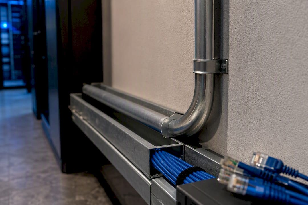
The 100 meter Ethernet limit is a hard ceiling for standard-compliant, certifiable installations: a 90 meter permanent link plus two 5 meter patch cords, no exceptions built into the spec. Some copper runs will technically pass traffic past that mark in controlled conditions, but they’re nonstandard, uncertifiable, and unreliable long-term. For anything that needs to hold up, use a midspan switch, convert to fiber with media converters, or deploy a PoE extender rather than gambling on a stretched copper run.
TL;DR:
- The 100 meter Ethernet limit is a strict standard based on channel length, including a 90 meter permanent link and 5 meter patch cords on each end.
- Beyond 100 meters, increased attenuation, crosstalk, and propagation delays cause unreliable Ethernet signals, especially at gigabit speeds.
- Cable quality, proper installation, and environmental factors significantly affect the actual reach, with Cat6a supporting full 100 meter 10GbE runs, unlike standard Cat6.
- Extending Ethernet beyond 100 meters requires equipment like switches, fiber conversion, or PoE extenders; stretched copper alone is unreliable and uncertifiable.
- Certifying a run near or over 100 meters demands comprehensive testing of insertion loss, crosstalk, and delay, which stretched or makeshift runs typically fail.
What TIA/EIA and IEEE Actually Specify About the 100 Meter Channel
The 100 meter figure isn’t arbitrary. It’s the sum of a defined channel: a 90 meter permanent link (the fixed cabling in walls and conduit) plus up to 5 meters of patch cord on each end, connecting equipment to wall jacks. TIA cable-plant guidance breaks down how insertion loss budgets and cable plant design drive that 90/5/5 split. Push past the permanent link allowance, even while staying under 100 meters total, and the channel no longer meets spec.

The IEEE 802.3 family sets the physical layer expectations that make this ceiling necessary. Both 100BASE-TX and Gigabit 1000BASE-T rely on 100 meters as the maximum twisted-pair segment length, and the PHY signaling for each assumes that length when calculating timing and voltage margins. Go longer, and the insertion loss budget the standard reserves for connectors, cable defects, and environmental noise gets consumed by distance alone, leaving no margin for anything else.
Why Does the 100 Meter Limit Exist in the First Place?
Four electrical realities converge at roughly 100 meters on copper twisted pair. Insertion loss (attenuation) climbs with both frequency and distance, so the higher-frequency signals used by Gigabit Ethernet degrade faster over length than the lower frequencies used by older 10BASE-T links.
Crosstalk, specifically near-end and far-end crosstalk (NEXT and FEXT), gets worse as cable length increases because adjacent twisted pairs inside the same jacket have more distance over which to couple noise into each other. Propagation delay and skew matter just as much for multi-pair standards like 1000BASE-T, which split data across all four pairs simultaneously. If one pair’s signal arrives even a few nanoseconds out of sync with the others, the receiver’s PHY can’t recover the symbol correctly. Every one of these effects compounds at once past the rated distance, which is why “it still works at 130 meters” in a lab test doesn’t mean it will work reliably in a data closet six months from now.
How Cable Quality and Installation Change Practical Reach
Not all cable rated for the same channel length performs the same way under stress. Cat5e, Cat6, and Cat6a carry different bandwidth and loss profiles: Cat6a supports 10GbE at the full 100 meter channel, while standard Cat6 can carry 10G only out to roughly 55 meters before insertion loss becomes a problem. Conductor gauge matters too. 23 AWG cable (common in Cat6 and Cat6a) has lower resistance than 24 AWG (common in cheaper Cat5e and Cat6), which affects both signal attenuation and PoE voltage delivery over distance.
Workmanship errors erode margin faster than most installers expect:
- Untwisting pairs more than half an inch during termination, which invites crosstalk
- Poor crimps or reused connectors that add unpredictable insertion loss
- Compression connectors installed without proper strain relief
- Hidden splices inside walls, buried in conduit, and forgotten
Electromagnetic environment plays a role too. Runs parallel to fluorescent ballasts, motors, or unshielded power conductors pick up noise that eats into the same margin the standard assumed would be clean.
Pro Tip: Before pulling a run near its rated maximum, check what’s already in the conduit. A CAT6 line sharing a tray with 277V lighting circuits for even 20 feet can fail NEXT testing that would otherwise pass with room to spare. Choosing the right bulk cable category and gauge up front avoids this entirely.
What Are the Best Ways to Extend Ethernet Past 100 Meters?
Extending reliable connectivity past a single 100 meter copper channel comes down to four field-proven approaches, each with its own trade-offs.
- Place a switch or Ethernet repeater mid-span. This resets the channel clock, giving you a fresh 100 meter budget on each side. It’s cheap and fast to deploy, but it adds a managed device (and a power source) somewhere you may not want one, and it introduces another point of failure to maintain.
- Convert to fiber with media converters or SFPs. This is the professional standard for anything beyond a single room. Multimode fiber (OM2/OM3) comfortably handles Gigabit links well past 100 meters, and single-mode extends that reach to kilometers for inter-building runs. Cost is higher upfront, but the loss budgets are predictable and the link is certifiable.
- Use PoE extenders or powered repeaters. These work when you need to push both data and power past 100 meters for a single device, like a remote camera or access point, but they add a power dependency at the extension point and rarely scale to multiple devices.
- Proprietary long-reach copper or Ethernet-over-coax. These exist and occasionally solve a specific retrofit problem, but Fluke Networks notes that claims of 150 to 200 meter reach on copper almost always depend on proprietary conductors or non-standard signal optimization. They’re rarely certifiable and rarely covered by a manufacturer’s standard cabling warranty.
Deciding between these options comes down to a handful of practical questions:
- How much bandwidth does the endpoint actually need, now and in three years?
- Does the device require PoE, and at what wattage class?
- Is this a single run or part of a backbone that will grow?
- Is the environment (outdoor, industrial, high-EMI) going to punish copper over time?
For a single security camera 130 meters out, a PoE extender might be the fastest fix. For a link between two buildings, fiber isn’t just the better option, it’s the only one that gets you a certifiable result.
How Does PoE Change the Math on Long Runs?
Power over Ethernet adds a second constraint that has nothing to do with data signaling: voltage drop. Every meter of copper has resistance, and resistance eats voltage as current flows through it. On a run pushing close to 100 meters, a device drawing near the top of its PoE class (802.3at’s 30W or 802.3bt’s 60 to 90W) may not receive enough voltage at the far end to boot reliably, even though the data signal tests fine.
Conductor gauge is the lever here. 24 AWG cable has more resistance than 23 AWG, so the same length and current draw produces a bigger voltage drop on thinner conductors. Mitigations worth considering:
- Specify 23 AWG cable for any run approaching 100 meters that will carry high-wattage PoE
- Add a local PoE injector closer to the device instead of powering from the far end
- Convert to fiber with a local switch, then power the endpoint from that closet
- Choose a lower-power endpoint class where the application allows it
What Should You Test to Certify a Long Ethernet Run?
A certifiable copper channel needs to pass wiremap, length, insertion loss, NEXT, return loss, and propagation delay (including skew between pairs). Certifiers report these against the TIA channel or permanent link limits, and any result exceeding those thresholds is a fail, full stop. This is exactly why a copper run stretched past 100 meters can’t be certified: even if it passes traffic in a quick functional test, it will not pass a certifier’s insertion loss or NEXT thresholds against the standard.
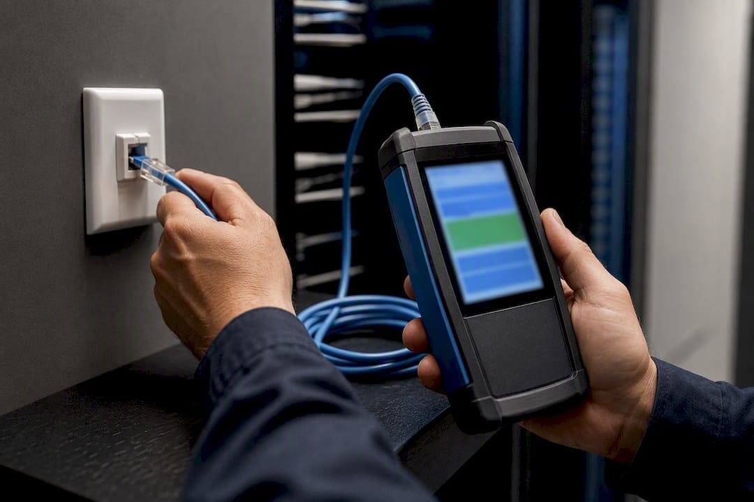
Fiber conversions need their own verification. Optical loss testing (OLTS) confirms the link meets its loss budget, while OTDR testing documents the fiber’s condition end to end, useful for troubleshooting and for handing the client a real record of what was installed.
Pro Tip: A functional link light means almost nothing on a run near the distance limit. Always pull certification numbers before signing off, not just a ping test.
A Field Checklist for Runs Near or Past 100 Meters
- Plan: Confirm bandwidth needs, PoE class, exact span distance, and environmental hazards (EMI sources, outdoor exposure) before choosing cable or media.
- Install: Match cable category and AWG to the requirement, terminate carefully, keep twists intact to the connector, and avoid kinking or over-tensioning during pulls.
- Test: Run full certifier tests on copper, or OLTS/OTDR on fiber, and document every result before calling the job complete.
Pro Tip: Keep a running spreadsheet of every run’s length, category, and test result across a building. When a tenant expands three years later, that record tells you instantly which closets have headroom left.
What Installers Actually See in the Field
Runs that “work” past spec usually work until they don’t. A camera feed that drops frames intermittently, a VoIP phone that reboots under load, an access point that never quite hits its rated throughput: these show up months after the punch list closes, not during the walkthrough. Cheap patch cords and rushed terminations cause more of these failures than distance itself.
Some contractors lean toward fiber for anything crossing floors or buildings, not because copper can’t occasionally be pushed, but because a fiber link with proper OLTS documentation never needs a callback explaining why “it worked in testing.”
— Ken
Certified Long Runs Without the Guesswork
A professional low voltage contractor is the alternative to guessing whether a stretched copper run will hold up. Instead of hoping a 120 meter cable pull survives a certifier, the channel needs to be designed correctly the first time, whether that means a properly terminated Cat6a run within the 90/5/5 allowance or a fiber conversion for anything longer.

Our structured cabling and fiber installation crews handle the full scope: cable plant design, structured CAT6 and CAT6a installation, fiber installation with termination and testing, on-site certification, and PoE load planning for security and access control systems. If your project involves an inter-building link, a run that needs formal certification, high-wattage PoE devices, or a tight service-level agreement that can’t tolerate a flaky connection, that’s exactly the point where a contractor earns its cost. Reach out to Cables and Chips to scope a structured cabling or fiber installation plan for your space.
Sources
- Extending and Testing Cable Runs Beyond 100 meters
- How to Make Cable Plants V3.0 (insertion loss and cable plant design)
- Ethernet over twisted pair
- Fiber Optic Gigabit Links Between Industrial Buildings
FAQ
Why Is My Ethernet Connection Limited to 100 Mbps?
A link negotiating down to 100 Mbps instead of Gigabit speed is usually a cable quality or length issue, not the 100 meter rule itself; check for Cat5 (not 5e) cable, damaged pairs, or a run exceeding the channel’s insertion loss budget.
Will Cat6 Work Over 100 Meters?
Standard Cat6 is rated to the same 100 meter channel as Cat5e and Cat6a for Gigabit Ethernet, but its 10GbE support drops to roughly 55 meters, so “will it work” depends entirely on the speed you need.
How Do You Extend Ethernet Past 100 Meters?
The supportable methods are a midspan switch or repeater to reset the channel, a media converter or SFP to switch to fiber, or a PoE extender for powered endpoints; stretched copper beyond spec is not a reliable option.
What Ethernet Cable Is Limited to 100 Mbps?
Older Cat5 cable, or any twisted-pair cabling with damaged pairs or excessive length, typically caps a connection at 100 Mbps because it can’t meet the insertion loss and crosstalk requirements Gigabit signaling demands.