
Door Contact Wiring: Circuits, Resistors and Testing
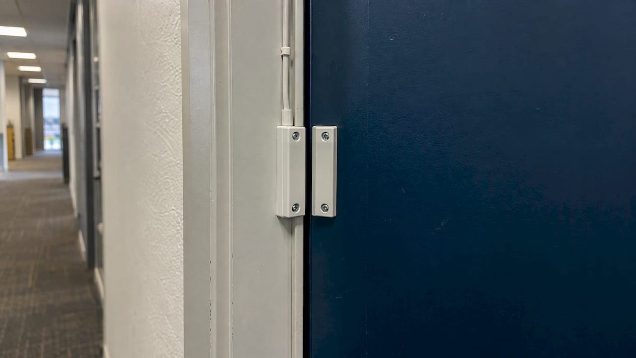
Wiring a door contact comes down to four decisions: which circuit type the contact is (normally closed or normally open), how it lands on a panel zone, whether the zone is supervised with an end-of-line (EOL) resistor, and how you prove it works before the ceiling closes. Get those four right and a door sensor is one of the most dependable devices on a security or access control system. Get one wrong and you chase false alarms for months.
This guide is written for IT directors, facilities managers, general contractors and security integrators who specify or inspect door contact wiring in commercial spaces. It covers magnetic door contacts and door sensors in a hardwired system, from the cable to the terminal to the final test.
TL;DR
- A magnetic door contact is a reed switch plus a magnet. It reports the position of the magnet, not the door, so alignment and gap matter as much as the wiring.
- Most commercial door contacts are wired normally closed (NC). Confirm the type with a multimeter in continuity mode before you terminate anything.
- Multiple NC contacts on one zone are generally wired in series, and NO contacts in parallel, but the panel manufacturer’s instructions decide the final method.
- Supervised zones need an EOL resistor so the panel can tell normal, alarm and fault apart. UL-listed installations on DSC panels must use single or double EOL.
- Test every contact with the magnet moving in and out, then document the zone, cable, resistor value and result at the panel or closet.
How a magnetic door contact works
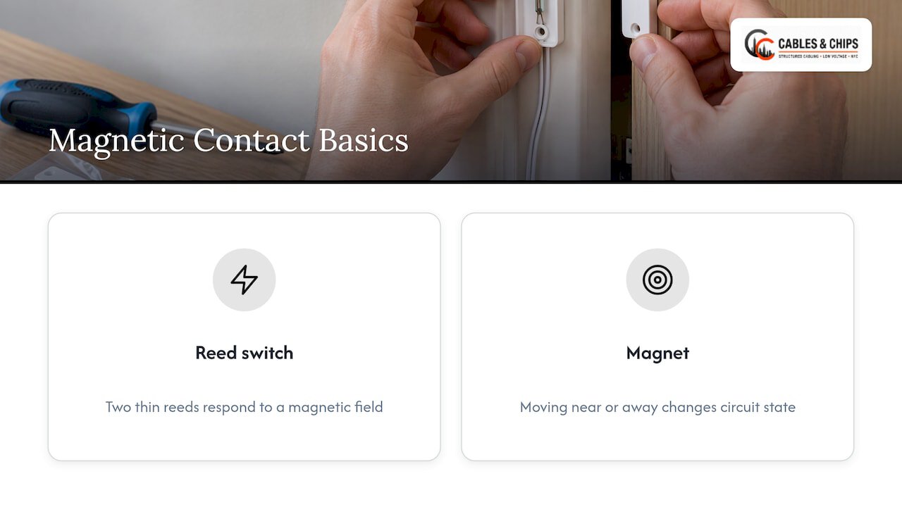
A magnetic door contact has two parts. One part holds a reed switch, and the other holds a magnet. A reed switch is a pair of thin metal reeds that respond to a magnetic field. According to one technical explainer on reed switches, when the magnet is close the reeds move and change the state of the circuit, and when the magnet moves away the reeds return to their original position.
The practical consequence is that the switch never detects the door itself. It detects the proximity of a magnetic field. That same source stresses that mechanical alignment is critical for reliable operation. A door that sags, a frame that shifts after a renovation, or a magnet mounted too far from the switch will produce nuisance alarms no matter how clean the cable run is.
Wiring and mounting are one job. When we survey a door, we check the gap between the two halves, the frame material, and whether the door swings or slides, before we decide where the cable exits.
Surface-mount and recessed contacts
Surface-mount contacts screw or adhere to the frame and door. Recessed contacts sit in drilled holes in the edge of the door and the jamb, so nothing shows on a finished door. Recessed units are common in new construction and office buildouts, where the cable is pulled before drywall closes. Surface units are common in retrofits, where the cable is fished through existing walls or run in raceway.
The wiring principle is the same for both. The two leads or screw terminals of the switch are the only electrical connection. Everything else is mounting.
Door sensor versus door contact
People search for both terms. In practice, “door sensor” often means the same magnetic contact, or in a residential product a wireless transmitter with a built-in magnet. This article covers the hardwired type, which is the standard in commercial buildings because it needs no batteries and can be supervised end to end by the panel.
Normally closed or normally open: identify the circuit first
Before you land a single wire, find out what the contact does at rest. The terms are standard electrical language. Schneider Electric’s technical FAQ defines normally open contacts as open when not actuated, and normally closed contacts as closed when not actuated.
For a door contact, “actuated” means the magnet is away from the switch, which means the door is open. That leads to the usual behavior:
| Contact type | Door closed (magnet near) | Door open (magnet away) |
|---|---|---|
| Normally closed (NC) | Circuit closed, continuity | Circuit opens |
| Normally open (NO) | Circuit open | Circuit closes |
A note on terminology: manufacturers sometimes describe a reed element by its behavior with the magnet present or absent, and sometimes by the state with the door closed. The explainer above notes that a common reed element is open with no magnet present and closes when the magnet is near, so the circuit is closed while the door is closed. Other devices may behave the opposite way. Do not assume from the label. Measure.
Confirm with a multimeter
Set the meter to continuity or resistance mode. With the contact disconnected from the panel and the magnet held against it, note the reading. Pull the magnet away and note it again. A circuit that shows continuity with the magnet near is a door-closed NC loop. A circuit that reads open with the magnet near is an NO arrangement.
This takes thirty seconds per device and prevents the most common commissioning mistake: a zone programmed for one type and a contact wired as the other.
Common (COM), NO and NC terminals
Some contacts, particularly Form C types, have three terminals labeled COM, NO and NC. You use COM plus whichever of the other two matches the circuit you want. Most basic door contacts have only two leads, and the type is fixed by how the switch is built. If you see three terminals and use all of them without a plan, you will create a short or an open loop.
Cable and gauge for door contacts
Door contacts carry almost no current, so the cable decision is about resistance, durability and noise rather than power.
Manufacturer documentation gives hard numbers. For DSC PowerSeries Neo panels, the zone wiring section of the installation guide specifies 22 to 18 AWG unshielded wire, with a maximum wiring resistance of 100 ohms, and requires single or double EOL for UL-listed installations. Other panels publish their own limits. Always read the installation guide for the exact panel on the job.
Three field habits keep door contact runs reliable:
- Use the right conductor count. A two-conductor run is enough for a basic contact. If the door also carries a request-to-exit device, a lock or a tamper circuit, pull a cable with enough pairs so you never have to splice later.
- Keep it away from line voltage. Do not run low voltage in parallel with power conductors. Cross them at right angles where you have to, and use separate pathways where code requires it.
- Protect the door transition. The flex point at a door frame is where cables fail. Use a rated door loop or a recessed contact with armored or jacketed leads.
For a deeper look at gauge decisions on door hardware runs, see our guide to sizing access control wire gauge. For the pathway and cable requirements around a door, our access control cabling requirements guide covers what a commercial project typically needs.
Where the cable goes before the walls close
The cheapest time to place a door contact cable is during rough-in. The cable is stubbed to the door frame, labeled, and left coiled for termination later. If the project is a buildout with several trades, coordination matters, because drywall, framing and door hardware crews will otherwise cover or cut the stub. Our low voltage rough-in guide explains the sequence and the inspection points.
Wiring one door contact to a panel zone
A zone is a pair of terminals on the alarm or access panel, usually marked ZONE or Z and COM, that the panel watches for a change. The basic wiring steps are the same across most panels:
- Identify the circuit type of the contact with a meter, as above.
- Run the cable from the door frame to the panel or to a field enclosure, with enough slack to service the device.
- Connect one lead of the contact to the zone input and the other to the zone common, or through the EOL resistor if the zone is supervised.
- Program the zone in the panel for the correct loop type, NC or NO, and for the resistor arrangement.
- Test and label the device.
One published step-by-step guide describes locating the monitoring unit terminals, usually COM, NO and NC, and for an NC circuit connecting the switch common to the panel zone input and the NC terminal to the EOL resistor. Treat that as a general pattern, not a rule. The terminal names, polarity and resistor value come from the panel manufacturer. If the panel’s guide shows a different layout, follow the panel’s guide.
Unsupervised versus supervised zones
An unsupervised zone is the simplest circuit. The panel sees only two states: closed (secure) and open (alarm). If a wire is cut or a connection corrodes open, the panel reads it as an alarm, and if a wire is shorted across the contact, the panel reads it as secure. That second case is the problem. A tampered or damaged circuit can mask a real opening without anyone noticing.
A supervised zone adds a resistor so the panel can recognize a third condition: a fault. That is why commercial and secure installations nearly always use one.
Wiring several door contacts on one zone
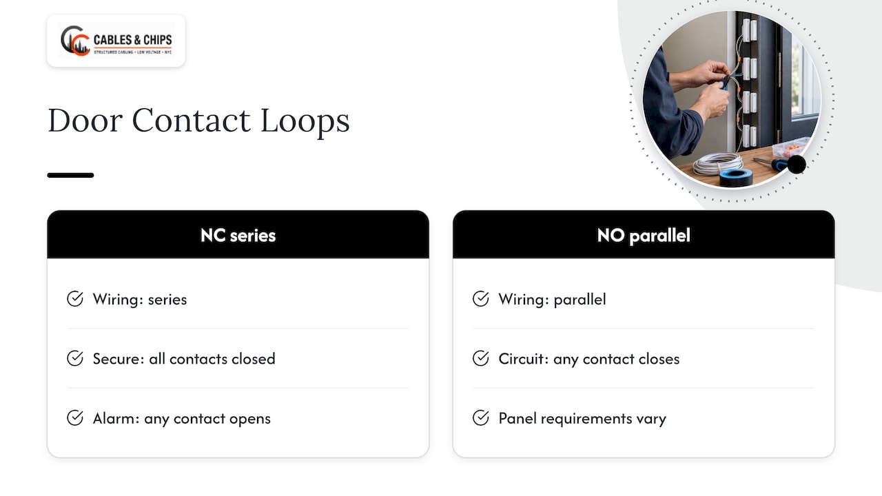
Sometimes a zone covers more than one opening, such as a pair of double doors or a row of storefront doors. The wiring method depends on the contact type. An industry reference on low voltage practice states that NC contacts are typically wired in series and NO contacts in parallel, with the specifics depending on the panel’s requirements.
Series (NC contacts)
In a series loop, the current passes through each contact in turn. Every contact must be closed for the loop to read secure. Open any one and the zone alarms. This is the typical arrangement for double doors where either leaf opening should trigger the zone.
The trade-off is identification. The panel reports one zone, not which leaf opened. If you need to know which door, give each door its own zone.
Parallel (NO contacts)
In a parallel loop, each contact bridges the same two conductors. Any one contact closing completes the circuit and signals the panel. This arrangement is less common for door contacts because most commercial installers prefer NC loops, which fail toward alarm when a wire breaks.
When to give each door its own zone
Use one zone per door when:
- The panel or security plan needs door-level reporting.
- Different doors have different schedules or bypass rules.
- The building has fire egress or life safety rules that require individual monitoring.
- Troubleshooting speed matters, since a single zone covering ten doors turns a fault into a walk-through.
On large floor plates, a single home-run per door back to the closet costs more cable but pays back in service time. It also keeps the cable plan clean and documented, which is what building management teams ask for at turnover.
End-of-line resistors: what they do and where they go
An EOL resistor turns a simple loop into a supervised one. With a known resistance in the circuit, the panel measures a specific value when everything is normal, a different value when the contact opens, and an out-of-range value when the wire is cut or shorted. That is how it distinguishes normal, alarm and fault conditions.
Single and double EOL
The DSC documentation states that zones can be wired to supervise NO devices, such as smoke detectors, or NC devices, such as door contacts, and that the panel can be programmed for single, double or triple end-of-line resistors. It adds that UL-listed installations must use single or double EOL only.
- Single EOL (SEOL): one resistor. The panel can read normal, alarm and open or short fault conditions.
- Double EOL (DEOL): two resistors, one across the contact and one in series. The panel can also report tamper separately from alarm on the same pair of wires.
The resistor value is not universal. It is set by the panel, commonly in the kilohm range, and the panel’s installation guide lists it. Use the exact value, and match the zone programming to it. A zone programmed for DEOL but wired with SEOL will report a permanent fault, and the reverse can leave a real tamper unreported.
Placement
The resistor belongs at the far end of the circuit, at the device, so that the whole run of cable is inside the supervised loop. A resistor at the panel only supervises the panel terminal. Where the contact is recessed and has no room, install the resistor in the nearest junction box or the device’s own terminal compartment and label it.
Panel programming
Wiring is half the job. The panel has to be told what the zone is. On DSC PowerSeries Neo panels, for example, zone definitions and the NC or EOL settings sit in programming sections the manufacturer documents in its zone wiring guide. Other manufacturers use different menus, but the pattern is the same: define the zone, choose the loop type, choose the resistor scheme.
Wiring door contacts to an access control system
Door position switches also feed access control controllers. The controller uses the contact to know whether a door is held open or forced open, and to relock correctly. The wiring concepts are the same: determine NC or NO, choose a supervised or unsupervised input, and use a resistor where the controller calls for one. What changes is the extra hardware at the door. A single opening may involve the door contact, an electric lock or strike, a request-to-exit device and a reader, each with its own cable.
That is where planning pays. A clean access control opening has a documented cable for each function, home-run to the controller location, tested and labeled. Our CCTV and access control installation service is built around that approach for commercial offices and secure facilities.
Testing a door contact before you close the job
Never trust a contact because it was new out of the box. Test every device at three stages: before install, after termination and after programming.
Bench and field test
A manufacturer’s device manual describes the basic method: set a multimeter to continuity or resistance mode and watch the reading change as you move the magnet near and away from the switch. The APEX device manual adds that if the circuit does not respond, you should check for loose or corroded wires at the terminals and confirm the magnet is aligned with the sensor.
A good field routine:
- Meter the contact alone, magnet near, then away. Record both readings.
- Meter the installed cable from the panel end with the contact connected and the door closed, then open.
- If an EOL resistor is installed, confirm the resistance matches the panel’s specified value with the door closed.
- Walk the door slowly open and watch the zone status at the panel or keypad. The zone should change at a small, consistent gap.
- Close the door, and confirm the zone restores to normal.
- Try the door in the full range of its swing and with the lock engaged, because a door under latch tension can shift the gap.
Troubleshooting false alarms and dead zones
Work from the simplest cause to the most complex.
- Check the gap and alignment. A magnet that is slightly too far, or a door that shifts with humidity or building movement, is the leading cause of nuisance alarms.
- Inspect terminals. Look for loose screws, nicked conductors and green or white corrosion on terminals. Reterminate rather than tighten a bad connection.
- Meter before replacing. Verify the switch changes state with a meter before you assume the device is faulty.
- Isolate the run. If several devices misbehave, disconnect the field wiring at the panel or a junction point to find out whether the problem is a specific cable or the panel itself.
- Look for stray voltage and interference. Erratic behavior on a hardwired zone can come from unwanted voltage or noise, especially where grounded metal enclosures are involved.
- Confirm the resistor and programming. A wrong value, or a zone programmed for the wrong loop type, produces constant faults that look like wiring problems.
Documentation
A tested door is only finished when someone else can find it later. Record the zone number, the door name, the cable ID, the contact type, the resistor scheme and value, and the date of the test. Put the record in the closet and with the building’s as-built files. This is what property managers and IT teams mean by serviceable infrastructure.
Common mistakes on commercial door contact jobs
These are the problems we see most often when we are asked to clean up or recommission a security system.
| Mistake | What it causes | Fix |
|---|---|---|
| Contact type not verified | Zone reads open or alarmed all the time | Meter the contact and program the zone to match |
| Resistor at the panel, not the device | Cut or shorted cable not detected | Move the resistor to the end of the run |
| Wrong resistor value or scheme | Permanent fault or unreported tamper | Use the panel manufacturer’s value and programming |
| Low voltage run beside power wiring | Intermittent false alarms | Separate pathways and cross at right angles |
| Unlabeled cables in the closet | Slow troubleshooting and risky changes | Label both ends and record in documentation |
| Large gap or loose mounting | Nuisance alarms as the door moves | Realign, re-shim, or use a contact rated for the gap |
| Spliced and taped joints at the door | Corrosion and open circuits over time | Terminate in a junction or use a continuous run |
Our perspective on door contact wiring
Door contacts look simple, and that is exactly why they get skipped in planning. A contact is two wires and a magnet. A bad one still takes a floor of a building into alarm at 2 a.m., and nobody can say which door did it.
In our work across New York City offices and secure facilities, we treat every door as its own small system: a documented cable, a confirmed circuit type, a supervised zone where the panel supports it, and a test result written down. We label both ends, we place the resistor at the device, and we leave the closet in a state where the next technician can read it.
Your network is only as strong as the infrastructure behind it, and the same is true of your security system. Clean low voltage cabling, tested and documented, is what keeps door contacts quiet until they have something real to report.
Ken
Door contact cabling for NYC offices and secure facilities
We handle door contact cabling as part of our CCTV and access control work: the cable runs, terminations, closet organization, testing and documentation for commercial offices, secure facilities and enterprise environments in New York City. The same team can handle structured cabling, MDF and IDF cleanup and rack work on the same visit, so the security cabling and the network cabling end up in the same documented system. We are licensed and insured, and we offer a no-obligation site survey.

If you are planning a buildout, a relocation or a security upgrade, start with a survey of the doors and the closet. See our CCTV and access control installation page or the full list of low voltage services, then schedule a site survey at https://cables.nyc.
Planning door contact wiring on a project
A short planning list saves rework on any commercial job.
- Make a door schedule. List every opening that needs a contact, a lock, a reader or an exit device, with the door type and frame material.
- Decide zone strategy early. One zone per door is usually easier to maintain. Grouped zones need a reason.
- Choose the panel before you pull cable. The resistor scheme, wire gauge limit and terminal layout all come from the panel documentation.
- Specify the contact for the door. Steel frames, wide gaps, outdoor exposure and overhead doors may need contacts rated for them.
- Pull and label at rough-in. Stub the cable to the frame location, label it, and confirm it with the other trades.
- Terminate, program, test and document. Close out each door with a recorded result.
If you are new to the trade vocabulary used above, our introduction to low voltage cabling defines the terms and the systems they apply to.
FAQ
Can I wire a door contact with any two-conductor cable?
A contact carries very little current, so the limit is the panel’s maximum loop resistance and the environment, not power. Some panel manuals specify 22 to 18 AWG for zone wiring, for example DSC’s guidance for its PowerSeries Neo panels. Check your panel’s guide, and use jacketed cable where the run is exposed or crosses a door.
Does it matter which wire goes to which terminal on a two-lead door contact?
On a basic reed contact with two leads, polarity does not matter, because the switch is a simple open or closed path. What matters is the zone input and common on the panel and, on supervised zones, where the resistor sits. If the contact has three terminals, such as COM, NO and NC, the terminals you choose set the circuit type.
Do I need an end-of-line resistor on every door contact?
You need one on every supervised zone. Commercial installations typically supervise zones so the panel can report faults, and DSC’s documentation states that UL-listed installations on its panels must use single or double EOL. Your panel’s installation guide gives the resistor value and the programming setting.
How do I tell whether a door contact is normally open or normally closed?
Disconnect it from the panel, set a multimeter to continuity, and hold the magnet against the switch. If you read continuity with the magnet near, the contact is closed when the door is closed. Pull the magnet away and the reading should flip. Program the panel zone to match what you measured.
Why does a door contact false alarm after it was working?
The usual causes are door movement that widens the gap, loose or corroded terminals, and cable damage at the door transition. Inspect and meter before replacing the device, and if several zones act up at once, isolate the cable runs at the panel to find whether the fault is in the field wiring or the panel.
Sources
- How do a magnetic door contact and a reed switch work?
- What are normally open and normally closed contacts? (Schneider Electric)
- Zone Wiring, PowerSeries Neo installation guide (DSC)
- Zone Wiring, PowerSeries Neo international guide (DSC)
- Zone wiring, PowerSeries Pro reference manual (DSC)
- TechComm Style Guide (series and parallel wiring)
- APEX Access Device manual