
Top 10 Building Infrastructure Cabling Problems to Fix Now
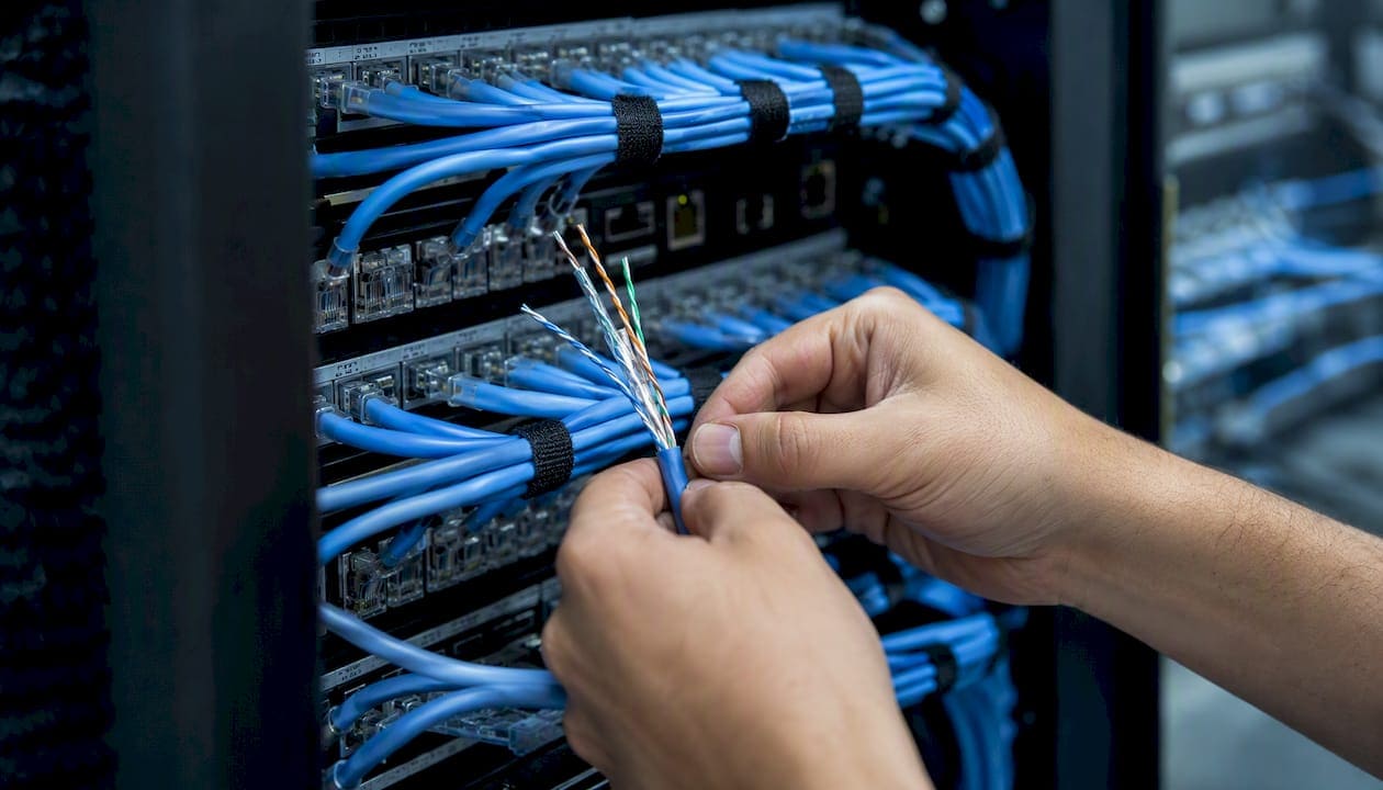
The top causes of building cabling failures are poor planning, installation errors, unmanaged physical stress, ignored standards, and skipped certification — and most are fixable with targeted inspection, correct tools, and a consistent test plan. Whether you are managing a new commercial build or troubleshooting an existing plant, the common building infrastructure cabling problems below appear on nearly every project that skips structured methodology.
Here are the 10 most frequent structured cabling faults and the fastest corrective action for each:
- Poor pathway planning: Audit conduit fill and capacity before pulling cable; reroute or add pathways if fill exceeds 40%.
- Ignoring TIA/EIA-568, BICSI, or NEC requirements: Pull the applicable standard into your contract language before work begins.
- Mixing cable categories or types incorrectly: Verify every cable reel label against the specification sheet before installation starts.
- Poor cable management and bundling: Replace nylon zip ties with hook-and-loop (Velcro) straps; re-dress bundles that show kinks or crush points.
- Skipping or inadequate testing and certification: Run a full certifier sweep on every link before handover; never accept a visual check as a substitute.
- Exceeding length limits or bend radius: Measure horizontal runs against the channel limit specified by standards (commonly around 90 meters) and maintain a minimum bend radius of 4x the cable’s outer diameter.
- Improper terminations and connector errors: Re-terminate any jack or plug showing excessive untwist (more than 0.5 inches / 13 mm) and re-test immediately.
- EMI and interference from power or HVAC: Re-route cables away from fluorescent fixtures and motors; cross power lines at 90 degrees where separation is impossible.
- Missing or inadequate labeling and documentation: Label every port with a TIA-606-style identifier and deliver as-built drawings at project closeout.
- Environmental damage (water, pests, mechanical): Inspect cable pathways quarterly for moisture ingress, rodent activity, and crush points near HVAC equipment.
Key Takeaways
The most important principle in structured cabling is this: a plant that is not tested to TIA-568 limits with a field certifier and documented with as-built drawings is not a finished installation, regardless of how it looks.
| Point | Details |
|---|---|
| Plan pathways before pulling | Audit conduit fill, coordinate with electrical trades, and confirm routes before any cable moves. |
| Follow TIA-568, BICSI N1, and NEC | Cite these standards in contract language; they define the limits inspectors and certifiers check. |
| Test every link with a certifier | Wiremap, NEXT, return loss, and length must all pass to TIA-568 limits before handover. |
| Keep untwist at 0.5 inches or less | Excessive untwist is the leading cause of NEXT failures and is fixed by re-termination, not cable replacement. |
| Cables and Chips delivers certified installs | Every project includes Fluke-certified test reports, labeled ports, and as-built drawings at closeout. |
Why do common building infrastructure cabling problems keep recurring?
Most cabling failures are not random. They trace back to a predictable set of planning and execution gaps that repeat across projects regardless of building size or budget.
Planning failures are the most upstream cause. Projects that skip a proper site survey routinely underestimate pathway capacity, ignore redundancy requirements, and fail to coordinate with electrical and MEP trades early enough. The result is conduit that is already full when the cabling crew arrives, or cable routes that run directly alongside high-voltage feeders. Understanding how building cabling infrastructure works before design begins prevents the most expensive rework.
Execution failures follow a different pattern. Over-tensioned pulls, inconsistent termination technique, and improper use of cable ties are crew-level errors that compound when there is no pre-pull walkdown and no installer checklist. A crew that pulls cable without confirming bend radius at every turn will create damage that only shows up weeks later under load. Knowing how to manage a cabling subcontractor on your jobsite is one of the most practical steps a facility manager can take to prevent these errors before they are buried in the ceiling.
Systemic causes are subtler. Specification drift during construction, budget-driven material substitutions (swapping Cat6A for Cat6 mid-project without updating the test plan), and missing as-built documentation all create problems that surface months after handover. The ITSIMM 8th edition emphasizes that many field failures are avoidable with basic project management steps: pre-pull meetings, documented pathways, and consistent installer training.
- Conduct a site survey and pathway audit before design is finalized.
- Coordinate with electrical and MEP trades to establish separation distances and conduit routing.
- Hold a pre-pull walkdown with the installation crew to walk every route.
- Require installer checklists for termination, support spacing, and bend radius compliance.
- Document every substitution in writing and update the test plan accordingly.
Pro Tip: *Require a signed pre-pull checklist from your installer before any cable moves.
What standards and codes must your cabling installation follow?
Three bodies of standards govern commercial structured cabling in the United States, and each addresses a different layer of the installation. Knowing which standard applies where is the fastest way to write enforceable contract language and know what inspectors will check.
TIA/EIA-568 is the primary performance and topology standard. TIA-568 defines the electrical tests required for certifying horizontal and backbone cabling, including wiremap, insertion loss, NEXT/FEXT, and return loss, and specifies installation constraints such as bend radius and separation from power. The 295-foot (90-meter) horizontal channel limit and the requirement for a minimum 2-inch separation from power conductors both originate here. Following TIA-568 produces a testable, warrantable installation.
ANSI/BICSI N1-2019 fills the gap between performance specifications and field practice. ANSI/BICSI N1-2019 defines minimum installation requirements for support structures, pulling practices, firestopping, cable terminations, and installation verification. Citing N1 in your contract scope reduces ambiguity and limits contractor substitution risk. Inspectors on commercial projects increasingly expect N1 compliance documentation at handover.
NEC/NFPA 70 governs the safety and fire-rating side. Article 800 covers communications circuits and requires cables to carry the correct plenum (CMP) or riser (CMR) rating for their installed environment. Article 725 addresses Class 2 and Class 3 remote-power circuits that often share pathways with data cabling. Mixing plenum and non-plenum cable in a plenum air-handling space is a code violation that triggers rework and can void your building’s certificate of occupancy.
Key installation limits from BICSI field practice: Minimum bend radius of 4x the cable’s outer diameter for Cat6-family UTP; maximum pull tension of approximately 25 lbs for 4-pair UTP; maximum conduit fill of 40% for three or more cables; and maximum untwist at termination of 0.5 inches (13 mm). Violating any of these typically produces failures that a certifier will catch — but only if you run one.
Key compliance checkpoints to include in every project spec:
- Require plenum (CMP) rating for all cables installed in air-handling spaces.
- Specify minimum 2-inch separation from 120V power conductors; 5 inches from 480V feeders.
- Mandate firestopping at every penetration per NEC 300.21 and local AHJ requirements.
- Require conduit fill calculations to be submitted before pulling begins.
- Cite ANSI/BICSI N1-2019 and TIA-568 by name in the scope of work.
How do you test and certify a commercial cabling installation?
Testing is where planning and installation quality become visible. A certifier run on every link before handover is the only way to confirm the plant performs to specification and to establish the baseline you will need for future troubleshooting.
Required tests for copper horizontal cabling (Cat6/Cat6A):
- Wiremap: Confirms correct pin-to-pin continuity and detects opens, shorts, miswires, and split pairs.
- Length: Verifies the channel stays within the 295-foot (90-meter) limit.
- Insertion loss: Measures signal attenuation across the channel; excessive loss points to cable damage, poor terminations, or overrun length.
- NEXT and PSNEXT: Near-end crosstalk tests; failures almost always trace to excessive untwist at termination or damaged pair geometry.
- Return loss: Measures impedance consistency; failures indicate a discontinuity such as a kink, crush point, or mismatched component.
- Alien crosstalk (ANEXT/PSAANEXT): Required for Cat6A channels; failures often indicate cables bundled too tightly or routed too close to other Cat6A bundles.
Recommended tools by task:
- Cable verifier (e.g., Klein Tools VDV Scout): Quick go/no-go wiremap check during rough-in; not a substitute for certification.
- Cable qualifier (e.g., NetAlly LinkRunner): Confirms link speed and PoE capability; useful for post-move troubleshooting.
- Field certifier (e.g., Fluke Networks DSX CableAnalyzer): The only tool that produces a pass/fail result against TIA-568 limits with a printed report. See the cable testing tools buyer’s guide for a full comparison.
- TDR (Time Domain Reflectometer): Locates the distance to a fault on a failing link; built into most modern certifiers.
What a failing parameter usually means:
| Test Parameter | Likely Root Cause | Fastest Field Fix |
|---|---|---|
| Wiremap open | Broken conductor or missed termination | Re-terminate; re-test |
| Wiremap split pair | Pairs crossed at punch-down | Re-terminate to T568B/A standard |
| Length overrun | Horizontal run exceeds 90 m | Pull new cable on shorter route |
| NEXT failure | Excessive untwist at connector | Re-terminate; keep untwist ≤ 0.5 in |
| Return loss failure | Kink, crush, or impedance mismatch | TDR to locate; replace damaged segment |
| Alien crosstalk (Cat6A) | Over-bundled cables | Separate bundles; re-test |
Most certification failures fall into four categories: wiremap, length, crosstalk, and return loss. Reading the certifier report parameter-by-parameter tells you exactly where to look before you touch a single cable.
Pre-handover certification checklist:
- Every horizontal link tested and passing to TIA-568 limits.
- Certifier reports saved in project file with link IDs matching port labels.
- Fiber links tested for insertion loss (OTDR trace for backbone runs).
- Test reports signed and delivered to the owner as part of the as-built package.
For renovation projects, test every link that was disturbed or re-routed.
What is the right on-site troubleshooting workflow for cabling faults?
A systematic troubleshooting approach starts with the fastest, lowest-cost checks and escalates only when simpler steps do not resolve the fault. Working out of order wastes time and can introduce new problems.
Step-by-step diagnostic sequence:
- Visual and physical check: Inspect the patch cord at both ends for bent pins, damaged boots, or a loose latch. Reseat the cord. Swap it for a known-good patch cord and retest.
- Verify the port: Move the connection to an adjacent port on the switch and patch panel. If the fault follows the cord, the cord is the problem. If it stays on the port, the port or the horizontal link is suspect.
- Verifier check: Run a cable verifier on the horizontal link to confirm wiremap continuity. A wiremap failure at this stage points to a termination error or a broken conductor.
- Qualifier check: Use a cable qualifier to confirm the link negotiates at the expected speed and that PoE voltage is within range. A link that negotiates at 100 Mbps instead of 1 Gbps on a Cat6 plant often points to a marginal NEXT or return loss result.
- Certifier run: Run a full TIA-568 certification sweep on the failing link. Read each parameter. NEXT failures point to termination geometry; return loss failures point to physical damage; length failures point to a break or an overrun.
- TDR distance-to-fault: If the certifier flags return loss or length, use the TDR function to locate the fault distance. This tells you whether re-termination will fix it or whether you need to pull new cable.
Decision guide for fault type:
- Total link down (no link light): Start at step 1. Most link-down faults are patch cords or unseated connectors.
- Intermittent drops under load: Skip to step 4 and run a certifier. Intermittent faults under load almost always indicate marginal NEXT or return loss, often caused by a near-connector termination defect or a bundle routed near a power source.
- Performance degradation (slow speeds, packet loss): Run the certifier first. Check bundle routing near fluorescent fixtures, motors, and HVAC units. EMI from these sources is a common culprit that re-routing or shielded cable resolves.
Escalation guideline:
- Re-terminate if the TDR places the fault within 3 feet of a connector.
- Pull new cable if the fault is mid-run, if the link fails after two re-terminations, or if physical damage (kink, crush, rodent chew) is confirmed.
- Involve the system vendor or warranty holder if the failure is on a manufacturer-certified channel that has not been disturbed.
Common installation mistakes and how to prevent them
Field installation errors are responsible for a significant share of cabling faults that show up at certification. Most are preventable with the right technique and the right materials.
Termination defects are the most frequent cause of NEXT failures. Excessive untwist at the connector is the single most common termination error: keep untwist to 0.5 inches (13 mm) or less, which is the limit for many Cat6A systems. Split pairs, where conductors from two different pairs are terminated together, cause wiremap failures that a verifier catches immediately. Miswiring (T568A vs. T568B inconsistency across a link) causes a wiremap failure that looks like a crossed pair. Re-terminate to the correct standard and re-test.
Mechanical damage often goes undetected during rough-in. Staples driven through cable jackets, cables bent sharply over conduit edges, and cables pinched under ceiling grid hardware all create impedance discontinuities that return loss testing catches. When a TDR places a return loss fault mid-run, look for the nearest physical constraint: a conduit bend, a support bracket, or a point where another trade crossed the cable path. Replacement is required when the jacket is breached or the pairs are visibly deformed.
- Use cable staples only on low-voltage-rated cable, and never drive them tight enough to compress the jacket.
- Maintain the manufacturer’s minimum bend radius (4x cable OD) at every turn, including at the patch panel entry.
- Never pull cable over sharp conduit edges without a bushing or grommet in place.
Cable type errors carry warranty consequences. Mixing Cat6 and Cat6A in the same channel degrades the channel to the lower category’s performance. Installing unshielded (UTP) cable in an environment that requires shielded (F/UTP or S/FTP) voids the system warranty and leaves the plant vulnerable to EMI. Verify every reel label before the pull begins, and document any substitution in writing.
Pro Tip: Use hook-and-loop (Velcro) straps for all horizontal and patch-field bundles. Over-cinching nylon zip ties creates permanent crush points that alter pair geometry and increase crosstalk — a defect that is invisible until the certifier runs.
How do environmental and infrastructure factors damage cabling?
The physical environment of a commercial building introduces failure modes that have nothing to do with installation technique. Identifying and mitigating these factors is part of any complete cabling maintenance plan.
EMI and RFI are the most common environmental causes of performance degradation. Fluorescent and LED ballasts, variable-frequency drives, elevator motors, and HVAC compressors all generate electromagnetic interference that couples into unshielded copper pairs. Safe routing practices include maintaining at least 2 inches of separation from 120V power conductors, 5 inches from 480V feeders, and crossing power lines at 90 degrees when separation is impossible. When re-routing is not feasible, specifying shielded cable (F/UTP or S/FTP) and properly grounding the shield at one end resolves most interference problems.
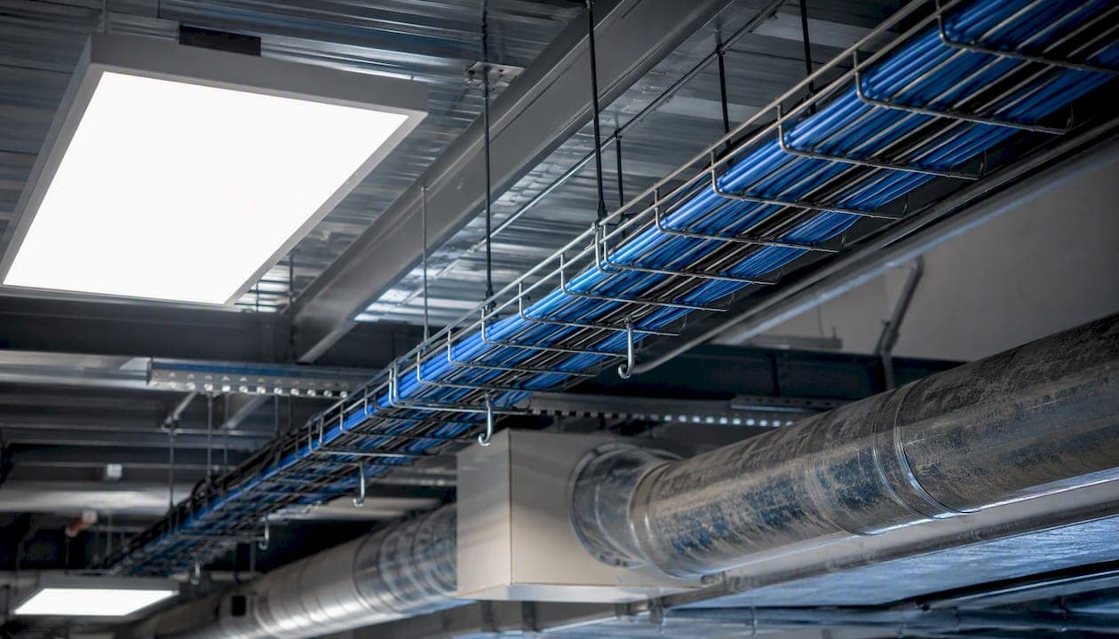
HVAC and moisture create a slower but equally damaging failure mode. Condensation on cold water pipes above cable trays wicks into cable jackets over time, degrading insulation resistance and causing intermittent return loss failures. Inspect cable pathways near air handlers and chilled water lines quarterly. Where moisture is chronic, use conduit rather than open cable tray.
Rodents and pests are a real problem in older commercial buildings, particularly in basement MDF rooms and cable risers. Rodent-chewed cables produce wiremap opens and return loss failures that a TDR locates precisely. Replacement is the only fix; re-termination cannot repair a chewed mid-run conductor.
Ceiling tile traffic and mechanical damage from other trades are underestimated causes of cable faults. Cables laid on ceiling tiles rather than supported on J-hooks or cable tray get stepped on during HVAC service calls. Every horizontal cable should be supported at intervals no greater than 5 feet and never resting on ceiling grid hardware.
Conduit fill and firestopping are code compliance issues that also affect performance. Overfilled conduit generates heat and makes future pulls impossible without damaging existing cables. Penetrations that are not firestopped per NEC 300.21 are a code violation that triggers rework at inspection. Seal every penetration with a listed firestop system rated for the cable type installed.
What does a good cabling maintenance and documentation program look like?
Documentation is what separates a cabling plant that gets fixed in 20 minutes from one that takes two days to diagnose. The as-built package and the maintenance schedule are not optional deliverables — they are the foundation of serviceability.
Labeling standard: Follow TIA-606 identifier conventions. Every port on every patch panel, every wall plate, and every fiber adapter should carry a unique identifier that matches the certifier report and the as-built drawing. Labels should be machine-printed, not handwritten, and applied to both ends of every link.
As-built package minimum contents:
- Floor plan showing cable routes, conduit paths, and support locations.
- Port schedule mapping every outlet ID to its patch panel port and switch port.
- Certifier test reports for every link, saved as PDF and in the certifier’s native format.
- Fiber OTDR traces for every backbone segment.
- Firestop inspection records for every penetration.
- Photos of MDF/IDF before and after installation.
Inspection and maintenance cadence:
- Quarterly visual inspection: Walk the MDF/IDF and spot-check patch field dressing, label legibility, and any new cable additions that were not documented.
- Semi-annual port check: Confirm active ports match the port schedule; identify and remove abandoned cables that are no longer connected to active equipment.
- Annual recertification (high-risk areas): Re-run certifier tests on links in areas with known EMI exposure, moisture history, or high physical traffic.
Good documentation reduces mean-time-to-repair during outages. When a link fails at 2:00 AM, a technician with a labeled port schedule and a certifier baseline can isolate the fault in minutes rather than hours. The structured cabling as-built documentation guide covers what a complete closeout package should include and how to structure it for long-term serviceability.
Labeling checklist:
- Every patch panel port labeled front and back.
- Every wall plate outlet labeled with TIA-606 identifier.
- Every fiber adapter labeled with strand number and circuit ID.
- Every MDF/IDF rack labeled with room ID and floor.
- Label format consistent across all locations in the building.
What are the most common cable fault types and how do you diagnose them?
Understanding the electrical and physical nature of each fault type lets you move from symptom to root cause without guessing. Each fault has a characteristic test signature that points directly to the fix.
- Open: A broken conductor or a missed termination. Symptom: link down, no link light. Wiremap test identifies the pair and the approximate location. TDR gives the distance to the break.
- Short: Two conductors touching, usually from a termination error or a crushed jacket. Symptom: link down or CRC errors. Wiremap identifies the shorted pair immediately.
- Split pair: Conductors from two different pairs terminated together, producing correct continuity but incorrect pair geometry. Symptom: wiremap passes on a basic toner but fails on a certifier; severe NEXT failure under load. Only a certifier or a verifier with pair-mapping capability catches this.
- Impedance mismatch: A discontinuity in the cable’s characteristic impedance, caused by a kink, crush, or mismatched component. Symptom: return loss failure, packet loss at higher speeds (10GBASE-T is particularly sensitive). TDR locates the discontinuity precisely.
- Excessive NEXT: Near-end crosstalk above the TIA-568 limit, almost always caused by excessive untwist at a connector. Symptom: intermittent errors under load, speed negotiation dropping to a lower tier. Re-termination with correct untwist resolves most cases.
| Fault Type | Symptom | Fastest Diagnostic Test | Likely Field Fix |
|---|---|---|---|
| Open | Link down | Wiremap / TDR | Re-terminate or pull new cable |
| Short | Link down / CRC errors | Wiremap | Re-terminate; inspect for crush |
| Split pair | NEXT failure, intermittent errors | Certifier wiremap | Re-terminate to correct standard |
| Impedance mismatch | Return loss failure, packet loss | TDR distance-to-fault | Locate and replace damaged segment |
| Excessive NEXT | Intermittent errors under load | Certifier NEXT sweep | Re-terminate; reduce untwist |
Use a TDR or certifier distance-to-fault function when the wiremap passes but return loss or NEXT still fails. A fault that is more than 3 feet from a connector is almost always a mid-run physical defect that requires cable replacement, not re-termination.
When should you call a cabling contractor instead of handling it in-house?
Some faults are within the reach of a competent IT team with a verifier and a patch cord inventory. Others require a licensed low-voltage contractor with a certifier, fiber test equipment, and documented installation practices. Knowing the boundary saves time and protects your warranty.
Clear triggers for contractor engagement:
- Backbone or fiber faults (OTDR required; fiber termination requires trained technicians and specialized equipment).
- Building-wide intermittent issues affecting multiple links simultaneously (systemic EMI, pathway damage, or a failed patch panel requires a structured sweep).
- Failed certification across more than a handful of links (indicates a systemic installation defect, not isolated termination errors).
- Firestop or NEC code violations identified during inspection (only a licensed contractor can perform and document compliant remediation).
- Warranty claims on a manufacturer-certified channel (the original installer or a certified partner must perform the work to preserve warranty eligibility).
- New cabling required for security camera systems or access control infrastructure, where CCTV and access control cabling requires specific pathway planning and documentation.
Contractor evaluation checklist:
- Holds a valid low-voltage contractor license for your state.
- Carries general liability and workers’ compensation insurance.
- Employs BICSI-registered technicians (BICSI Installer 1 or 2, RCDD for design).
- Delivers certified test reports (Fluke DSX or equivalent) for every link at closeout.
- Provides as-built drawings and a labeled port schedule as standard deliverables.
- Offers manufacturer-backed channel warranty (e.g., Belden, Commscope, or equivalent).
Questions to ask a bidder:
- What certifier model do you use, and will you deliver the native test files?
- How do you handle firestopping at penetrations, and who inspects it?
- What is your process if a link fails certification after handover?
- Can you provide references from commercial projects of similar scope in the past 24 months?
Require a complete closeout package in the contract before signing. A contractor who cannot commit to delivering test reports and as-builts at handover is a contractor who will not deliver them.
Field notes from Cables and Chips: real mistakes we’ve fixed
After more than 40 years of structured cabling work across commercial offices, secure facilities, and enterprise environments in New York City, certain problems appear on nearly every remediation project. Two patterns stand out.
The certifier reports showed NEXT failures concentrated near the patch panel, not at the wall plates. The root cause was a termination crew that had been untwisting pairs 1.5 inches or more to seat them in the keystone jacks, well beyond the 0.5-inch limit. Every failing link required re-termination at the patch panel end. After re-termination and re-test, all links passed. The lesson: NEXT failures concentrated at one end of a link almost always point to the termination at that end.
Case 2: Intermittent outages caused by a miswired patch panel. A financial services office reported intermittent connectivity drops on a cluster of workstations. The patch panel had been partially rewired during a desk move, and two pairs had been split across the wrong punch-down positions. The wiremap passed on a basic toner (which does not detect split pairs) but failed immediately on a certifier. Re-terminating the affected ports to the correct T568B standard resolved the issue in under an hour. The lesson: always use a certifier, not a toner, after any patch panel modification.
Pre-installation inspection checklist (copy and use):
- Walk every cable route and confirm conduit fill is below 40%.
- Verify cable reel labels match the specification (category, rating, manufacturer).
- Confirm bend radius compliance at every turn and at patch panel entry points.
- Check that all penetrations are firestopped before cables are pulled through.
- Inspect patch field dressing: no over-cinched zip ties, consistent slack loops, labels applied.
- Cross-check port labels against the port schedule before the certifier run.
- Confirm certifier test reports are saved and match the labeled port IDs.
Preserve test report files and installation photos. They are your proof of compliance and your fastest diagnostic tool when a fault appears six months after handover.
What the field actually teaches you about cabling quality
The most avoidable mistake in commercial cabling is not a technical error. It is the decision to skip the certifier run because the schedule is tight and “everything looks fine.” A visual check confirms that cable is present. It tells you nothing about whether it performs.
Every project that skips certification trades a few hours of test time for an unknown number of future outage hours. The certifier report is not a formality. It is the only document that proves the plant was built to specification on the day it was handed over. Without it, you have no baseline for future troubleshooting, no warranty claim support, and no way to distinguish a new fault from a pre-existing one.
For facility and IT managers working with installers: write the test requirement into the contract before work begins. Specify the certifier model or an equivalent. Require native test files, not just printed summaries. And insist on a labeled port schedule that matches the test report IDs. These three requirements cost nothing to add to a scope of work and eliminate the most common post-handover disputes.
What to check first on any cabling complaint, in order: patch cord, port, horizontal link wiremap, certifier sweep. That sequence resolves the majority of faults without pulling a single cable.
Cables and Chips delivers certified, documented cabling installations in New York City
When a cabling plant has systemic failures, missing documentation, or needs to be built right the first time, the answer is a contractor who treats testing and documentation as deliverables, not afterthoughts.

Cables and Chips provides CAT6 and CAT6A structured cabling installation for commercial offices and secure facilities across New York City, with every project backed by Fluke-certified test reports, labeled port schedules, and complete as-built drawings at closeout. The team also handles fiber backbone installation and testing, network closet cleanup and organization, abandoned cable removal, and remedial re-termination work on existing plants that have failed certification. For projects that need a full infrastructure review before design begins, the structured cabling system components guide outlines exactly what to specify and what to expect at handover.
Contact Cables and Chips to schedule a site survey for your next installation or remediation project.
Sources
The following standards and resources are the primary references for commercial structured cabling in the United States. Each is worth citing directly in project specifications and contractor scopes of work.
FAQ
What are the most common network infrastructure cabling problems?
The most frequent structured cabling faults are wiremap errors (opens, shorts, split pairs), NEXT failures from excessive untwist at terminations, return loss failures from kinks or crush points, and length overruns. Most trace to installation errors or skipped testing rather than defective materials.
What causes intermittent cabling and connectivity issues?
Intermittent faults most often result from marginal NEXT or return loss on a link that passes under light load but degrades under traffic. Common causes include near-connector termination defects, cables routed near EMI sources such as fluorescent ballasts or motors, and over-cinched cable bundles that have altered pair geometry.
What are the most common types of cable faults?
The four primary fault types are opens (broken conductor), shorts (conductors touching), split pairs (incorrect pair geometry at termination), and impedance mismatches (kinks or crush points). Each produces a distinct certifier test signature: opens and shorts appear on wiremap, split pairs show as NEXT failures, and impedance mismatches appear as return loss failures.
How do you troubleshoot a cabling problem on-site?
Start by swapping the patch cord and reseating connectors, then move the connection to a different port to isolate whether the fault follows the cord or stays on the link. Run a verifier for wiremap continuity, then a full certifier sweep if the verifier passes. Use the TDR distance-to-fault function to decide between re-termination and cable replacement.
When should a facility manager hire a cabling contractor?
Hire a contractor when faults span multiple links simultaneously, when fiber backbone testing or termination is required, when certification failures indicate a systemic installation defect, or when firestop or NEC code violations need documented remediation. Cables and Chips handles all of these scenarios for commercial clients across New York City, delivering certified test reports and complete as-built documentation at project closeout.