
Commercial WiFi Cabling Best Practices for IT Pros

Install a standards-based, pre-cabled grid with a minimum of two Category 6A runs per wireless access point (WAP) and 100% permanent-link certification before any network goes live. That single sentence captures the core of commercial wifi cabling best practices, and every decision in your design, specification, and acceptance process should trace back to it.
Your network is only as strong as the infrastructure behind it. The highest-priority practices to implement immediately:
- Plan before construction begins. Coordinate with architects and general contractors to place telecom rooms and pathways before walls close.
- Specify Cat6A as the baseline. Cat6A supports Wi-Fi 6/6E/7 throughput and the higher PoE loads modern access points demand.
- Run a minimum of two Cat6A drops per WAP. ANSI/TIA-568.1-E requires this when balanced twisted-pair is used; it supports aggregated backhaul and PoE headroom.
- Design a pre-cabled coverage grid. Use 18.3 m (60 ft) square cells with equipment outlets at cell centers per TSB-162-B.
- Keep horizontal permanent links within 90 m. Total channel length, including patch cords, must not exceed 100 m.
- Reserve 40–50% pathway capacity. Size trays and conduits for future moves, adds, and changes from day one.
- Require 100% permanent-link testing with a Level V field certifier and exportable test reports covering insertion loss, return loss, NEXT, and PSNEXT.
- Demand complete as-built documentation at handover: drawings, cable schedules, rack elevations, and machine-readable test files.
Actual routed paths through ceilings, walls, and conduit bends consistently run longer than floor-plan measurements suggest.*
Key Takeaways
| Point | Details |
|---|---|
| At least two Cat6A drops per WAP | ANSI/TIA-568.1-E requires a minimum of two Cat6A runs per access point for backhaul and PoE redundancy. |
| 90 m permanent-link limit | Horizontal copper runs must stay at or below 90 m; total channel including patch cords cannot exceed 100 m. |
| 40–50% pathway reserve | Size trays and conduits so current fill does not exceed 50–60%, preserving capacity for future MACs. |
| 100% Level V certification | Every permanent link must be tested with a Level V certifier; reports must include insertion loss, return loss, NEXT, and PSNEXT. |
| Cables and Chips | Cables and Chips installs, tests, and documents Cat6A and fiber infrastructure to ANSI/TIA standards for commercial clients in New York City. |
1. Plan early and design for current and future Wi-Fi needs
Good wifi infrastructure planning starts before a single wall stud goes up. Engage your cabling contractor during schematic design, not after construction documents are issued. That early coordination lets you place telecom rooms where they actually serve the floor plate, size pathways correctly, and avoid the conduit conflicts that force expensive reroutes later.
The foundation of any commercial WLAN design is the coverage grid. TSB-162-B recommends 18.3 m (60 ft) square cells with one or more equipment outlets at the center of each cell. Translate that grid onto your floor plan and you get a WAP outlet schedule you can hand directly to a contractor. Offset cells between floors to reduce co-channel interference between stacked access points.
Telecom room placement drives everything downstream. Keep horizontal runs within the 90 m permanent-link limit by positioning MDF/IDF rooms so no outlet is more than roughly 70 m of actual routed cable from the nearest room (the remaining 20 m covers patch cords and route deviations). For large floor plates, that often means one IDF per floor or per wing.
Design-phase checklist items to include in your RFP:
- Site survey and RF heat map showing proposed WAP locations and coverage overlap
- Telecom room locations with square footage, power, and cooling specifications
- Pathway maps showing tray routes, conduit sleeves, and fill calculations
- Cable schedule listing every outlet, its room, its WAP assignment, and its cable category
- Coordination drawing showing separation from electrical panels, HVAC ducts, and lighting ballasts
That gap is your 40–50% reserve for future MACs without a re-pull.*
2. Standards and code rules you must follow
Referencing the right standards in your specifications is what separates a contractually enforceable installation from a verbal agreement. The core documents to cite:
- ANSI/TIA-568.1-E — the primary commercial building telecommunications cabling standard; governs cable categories, permanent-link limits, and WAP cabling minimums
- TIA-569 — pathways and spaces; governs telecom room sizing, conduit fill, bend radius, and separation from electrical sources
- TIA TSB-162-B — the WAP-specific technical service bulletin; defines the 18.3 m grid, equipment outlet placement, and cabling recommendations for WLANs
- BICSI guidance (BICSI 007/008) — positions structured cabling as part of intelligent building infrastructure, integrating WAP placement with IoT and building automation systems
- Local building and electrical codes — NEC Article 800 governs communications wiring; local AHJ requirements may add plenum-rating mandates or conduit fill limits
The 90 m permanent horizontal copper limit and 100 m total channel limit are non-negotiable. In practice, that means your routed cable length from patch panel to outlet must stay at or below 90 m, with no more than 10 m combined for patch cords at both ends. For buildings with long floor plates or high ceilings, this constraint directly determines how many telecom rooms you need.
Standards also set the floor for testing. Acceptance documentation must include test reports generated by a Level V certifier, with results for every permanent link in the installation.
3. Which cable types and topologies work best for commercial Wi-Fi
Category 6A is the correct baseline for WAP horizontal cabling in any new commercial installation. It supports the full 10GBASE-T channel at 100 m, handles the higher PoE++ loads that Wi-Fi 6E and Wi-Fi 7 access points draw, and provides the headroom needed for aggregated backhaul when two drops per AP are bonded at the switch. Cat6 is acceptable in lower-density retrofits where budget is constrained and WAPs are single-radio, but it limits future upgrade paths. Cat5e has no place in a new commercial WLAN design.
For backbone runs between MDF and IDF rooms, specify fiber. OM4 multimode handles distances up to 400 m at 10 Gbps and is the practical choice for intra-building runs in most commercial buildings. OS2 singlemode is the right call for campus environments, inter-building links, or any run exceeding OM4’s distance limits. A dedicated fiber optic backbone keeps backbone capacity independent of copper horizontal runs and gives you a clear upgrade path to 25/40/100 Gbps without touching the horizontal plant.
Cable selection guidance at a glance:
- Cat6A UTP: standard WAP horizontal cabling in most commercial spaces
- Cat6A STP/ScTP: specify in high-EMI environments (near MRI suites, industrial equipment, or dense electrical panels) where shielding provides measurable noise rejection
- OM4 multimode fiber: backbone runs up to 400 m at 10 Gbps; most intra-building scenarios
- OS2 singlemode fiber: campus or inter-building links; future-proofs for 100 Gbps+ upgrades
- Plenum-rated (CMP) jacket: required in air-handling spaces; never substitute riser-rated cable in a plenum ceiling
- Riser-rated (CMR) jacket: acceptable in vertical runs between floors in non-plenum spaces
Stick to a star topology for horizontal cabling. Every outlet home-runs to the nearest telecom room. Avoid bridged taps and limit consolidation points to one per horizontal run, located at least 15 m from the telecom room and documented in the cable schedule.
Pro Tip: In densely bundled PoE runs inside plenum spaces, thermal derating can reduce your allowable cable length. TSB-162-B includes thermal derating guidance — apply it when you have more than 24 bundled cables carrying PoE simultaneously.
4. WAP cabling: outlet counts, placement, power, and redundancy
Two Cat6A drops per access point is the standard, not a luxury. The reasoning is straightforward: Wi-Fi 6 and Wi-Fi 6E access points can aggregate multiple uplinks for higher backhaul throughput, and a second drop provides PoE redundancy if one switch port fails. For high-density environments — conference centers, trading floors, auditoriums — a third drop is worth specifying.
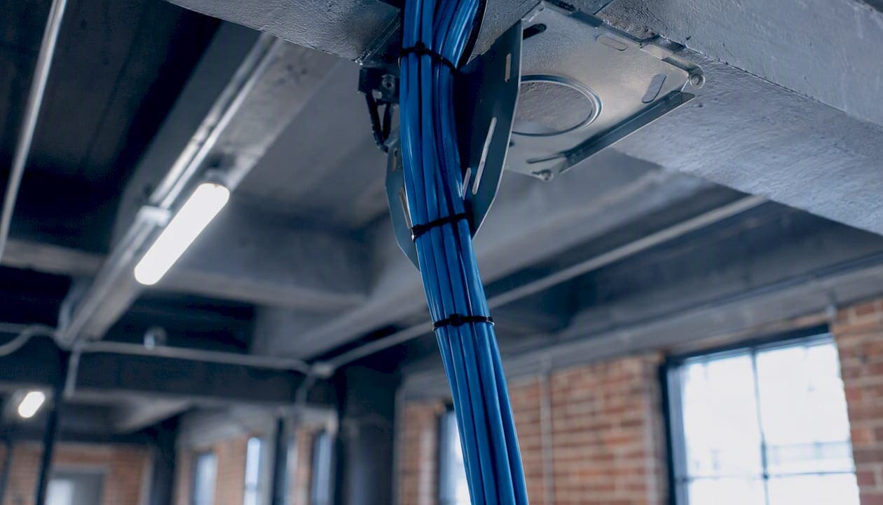
Translate the 18.3 m (60 ft) grid into your outlet schedule by overlaying it on the architectural floor plan. Each cell center gets one equipment outlet with two Cat6A runs. On multi-story buildings, offset the grid by half a cell between floors to reduce vertical co-channel interference. The result is a predictable outlet schedule you can price and build from.
WAP cabling specifics checklist:
- At least two Cat6A runs per WAP, home-run to the nearest IDF
- Equipment outlet located at cell center, within 5 m of the planned WAP mount point
- Maximum 5 m equipment cord from outlet to WAP (included in the 10 m equipment cord allowance)
- One consolidation point maximum per horizontal run, at least 15 m from the telecom room
- PoE budget calculated at the switch level: account for all simultaneous WAP loads plus 20% headroom
- Dedicated 20A circuit in each telecom room for PoE switches; UPS-backed where uptime is critical
For high-ceiling spaces (above 9 m), service loops and drop poles add measurable cable length. Include those additions in your permanent-link length calculation and test those links specifically. A drop pole in a 12 m atrium can add 6–8 m to a run that looked compliant on the floor plan.
Pro Tip: Map your WAP cabling plan to the RF heat map before finalizing outlet locations. A 2 m shift in outlet placement can mean the difference between a clean ceiling mount and a visible conduit extension.
5. Pathway, containment, and cable management rules that protect signal integrity
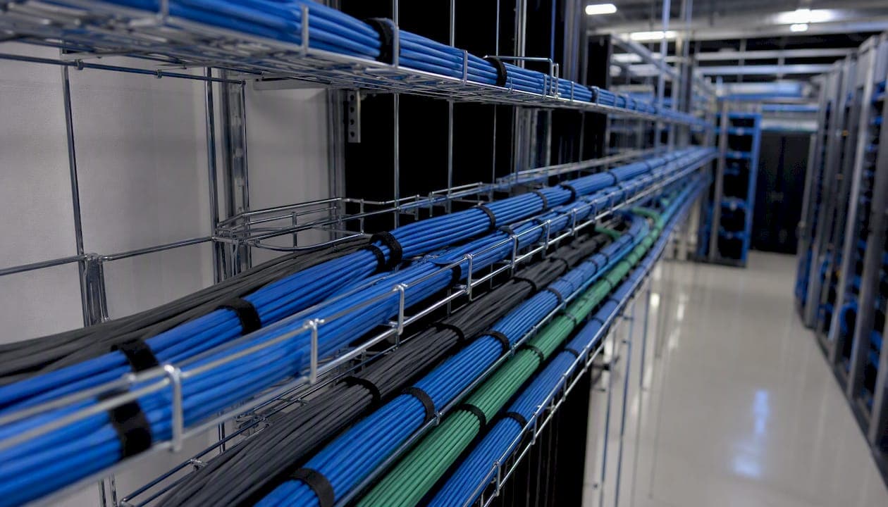
Poor cable management is the leading cause of performance failures that don’t show up until after occupancy. Common installation errors include zip ties cinched tight enough to deform the jacket, bend-radius violations at tray corners, and pathways filled beyond capacity so that pulling new cables damages existing ones.
The rules that matter most:
- Separation from electrical: maintain a minimum 50 mm (2 in.) separation from unshielded power conductors up to 2 kVA; increase to 100 mm (4 in.) near fluorescent lighting ballasts and 300 mm (12 in.) near electrical panels, per TIA-569
- Bend radius: minimum bend radius for Cat6A is 4x the cable diameter; for fiber, follow manufacturer specs (typically 10x the cable diameter for installation, 15x for permanent bends)
- Pulling tension: never exceed 25 lbf for Cat6A during installation; use a fish tape or pull string with a tension gauge on long runs
- Tray fill: size cable trays so the current design occupies no more than 50–60% of usable fill; the 40–50% reserve accommodates future MACs without a re-pull
- Bundling: group cables by system (data, voice, security) within trays using Velcro wraps, not zip ties; avoid over-bundling PoE cables in high-ambient-temperature spaces
- HVAC clearance: route trays at least 300 mm (12 in.) from HVAC supply ducts to avoid temperature extremes that derate cable performance
For multi-tenant buildings, coordinating shared pathway spaces and service corridors early prevents the fill-rate conflicts that become expensive disputes during tenant buildouts.
Pro Tip: Before closing ceilings, walk every tray run with the GC and photograph the fill level, separation distances, and bend points. Those photos become your baseline for future inspections and dispute resolution.
6. Termination, labeling, and as-built documentation
Correct termination starts with pair untwist limits. For Cat6A, untwist no more than 13 mm (0.5 in.) at the termination point. Use IDC (insulation displacement connector) punch-down tools with the correct blade for the hardware category, and always use matching-category jacks, patch panels, and connecting hardware throughout the channel. Mixing a Cat6A cable with a Cat6 jack downgrades the entire link to Cat6 performance.
Labeling standard: reference TIA-606 hierarchical identifiers. A practical label format for WAP outlets:
[Building]-[Floor]-[Room/Zone]-[Outlet Number]
Example: NYC-03-NW-042 identifies the 42nd outlet in the northwest zone of the third floor of the NYC building. Apply the same identifier to both ends of the cable, the patch panel port, and the cable schedule row. Every label should be machine-printed, not handwritten, and rated for the environment (plenum-rated labels in air-handling spaces).
As-built deliverables to require at handover:
- As-built floor plans showing every outlet location and cable route
- Complete cable schedule in editable spreadsheet format (Excel or CSV)
- Rack elevations showing patch panel port assignments
- Test reports in exportable format (PDF and manufacturer’s native file, e.g., .flw for Fluke)
- Redline drawings showing any deviations from the design drawings
Patch panels should be dressed with consistent slack loops, labeled on both the front and rear, and documented in the rack elevation drawing. A well-dressed patch panel cuts troubleshooting time from hours to minutes when a link fails.
For a deeper look at producing and managing as-built documentation, Cables and Chips provides a dedicated guide covering file formats, naming conventions, and version control.
7. Field testing, certification, and acceptance criteria
Testing is where specifications become verifiable facts. The Fluke DSX series is the industry reference class for this work. Fluke Networks’ professional testing guidance specifies that test reports must include insertion loss, return loss, NEXT (near-end crosstalk), PSNEXT (power sum NEXT), and length for every link. For shielded installations, add shield continuity and transfer impedance to the report requirements.
Numbered acceptance process:
- Pre-pull verification: confirm cable category, jacket rating, and lot numbers match the specification before installation begins
- Post-termination continuity check: verify pin-to-pin continuity and absence of shorts before certifying
- 100% permanent-link certification: run the full suite of Level V tests on every link; no sampling
- Review and remediation: any failed link gets reworked and retested before handover; document the failure cause and corrective action
- Final report delivery: contractor submits PDF and native tester files; owner or owner’s rep spot-checks 10% of links with an independent certifier if desired
- Sign-off: written acceptance signed by both parties, with test report file names listed in the handover document
Acceptance thresholds are set by the cable category tested. A Cat6A permanent link must pass all parameters defined in ANSI/TIA-568.2-D at the Cat6A limit. Any link that fails any single parameter fails the entire link. Partial passes are not accepted.
Machine-readable test data lets you diagnose future performance issues without re-pulling cable. For more on why testing matters before a network goes live, the consequences of skipping certification are well-documented.
Pro Tip: Specify that test reports must use the permanent-link adapter configuration, not the channel configuration. Channel tests include patch cords and can mask marginal terminations that will cause intermittent failures under load.
8. Ongoing maintenance, moves/adds/changes, and lifecycle planning
A cabling plant without a MAC policy degrades faster than the cable itself. Every move, add, or change that goes undocumented creates a gap between the as-built record and reality. Within two years of occupancy, an undocumented installation becomes effectively unmaintainable.
Maintenance and lifecycle best practices:
- MAC policy: require written work orders for every change; update the cable schedule and as-built drawings within five business days of completion
- Contractor documentation: any contractor performing MAC work must deliver updated test reports and label changes as a condition of payment
- Periodic retesting: retest links that have been reterminated, re-routed, or subjected to physical disturbance; full recertification is warranted after major renovations
- Lifecycle budgeting: Cat6A horizontal cabling has a practical service life of 15–20 years when properly installed and maintained; fiber backbones often outlast the electronics they serve; plan capital refresh cycles accordingly
- Troubleshooting discipline: when a WAP underperforms, test the permanent link first before replacing the access point; a marginal return-loss result on a link that passed certification often points to a connector that was re-terminated without proper pair untwist control
Pro Tip: Keep a spare set of tester adapters and a calibration certificate on file. When a link dispute arises with a contractor, having your own calibrated Level V certifier lets you produce independent results rather than relying on the contractor’s data.
9. Copyable RFP/spec checklist and acceptance-test snippet
This section gives you language you can drop directly into a contractor RFP or project specification. Adjust scope references and building identifiers to match your project.
Mandatory RFP checklist items:
- Standards reference: all work shall conform to ANSI/TIA-568.1-E, TIA-569, TIA TSB-162-B, BICSI guidelines, and applicable NEC and local codes
- Cable specification: Category 6A, 100-ohm, 4-pair UTP (or STP where specified), plenum-rated (CMP) in air-handling spaces, riser-rated (CMR) elsewhere
- WAP outlet schedule: minimum two Cat6A runs per WAP location per the attached outlet schedule; locations per RF heat map and coverage grid drawing
- Pathway capacity: all trays and conduits sized to no more than 50–60% fill at project completion
- Testing requirement: 100% permanent-link testing with a Level V field certifier; test reports in PDF and native tester format required before final payment
- Deliverables: as-built drawings (PDF + editable), cable schedule (Excel/CSV), rack elevations, test reports, and label legend
Sample spec snippet (copyable contract text):
Acceptance test snippet:
- Pass criteria: all parameters at or above the ANSI/TIA-568.2-D Cat6A limit for permanent-link configuration
- Failed links: reworked and retested; failure cause documented in writing
- Report naming convention:
[ProjectID]_[Floor]_[Panel]_[Port]_[Date].pdf
Pro Tip: Include a clause requiring the contractor to retain raw tester data for 12 months post-handover. If a link fails during the warranty period, that data tells you whether the failure was present at installation or developed afterward.
| RFP Item | Minimum Requirement |
|---|---|
| Cable category | Cat6A (CMP in plenums, CMR in risers) |
| Drops per WAP | 2 minimum; 3 for high-density zones |
| Permanent-link length | 90 m maximum |
| Tray fill at completion | 50–60% maximum |
| Testing standard | 100% permanent link, Level V certifier |
| Test report format | PDF + native tester file |
| As-built deliverables | Drawings, cable schedule, rack elevations |
The real cost of cutting corners on commercial cabling
The standards and checklists in this article exist because the consequences of skipping them are predictable and expensive. A WAP that drops connections intermittently in a conference room costs far more in lost productivity and IT labor than the cost of a second Cat6A drop at rough-in.
What practitioners see repeatedly is that the failures are almost never caused by the cable itself. They come from the installation: a bend radius violated at a tray corner, a consolidation point that was never documented, a test report that was never produced. The Belden structured cabling design guide makes the same point: standards-based practices, 100% testing, and proper documentation are not overhead. They are the product.
The other underestimated factor is the pace of wireless evolution. Wi-Fi 6E is deployed now. Wi-Fi 7 is entering commercial buildings. Each generation increases client density and aggregate throughput demands, which is exactly why the two-drop-per-AP practice exists. A Cat6A plant installed correctly today will support at least two wireless generations without a horizontal re-pull. That is the return on doing it right the first time.
Cables and Chips brings these standards to your NYC project
Cables and Chips delivers every item on this checklist for commercial clients across New York City. From pre-construction site surveys and RF-coordinated outlet schedules to Cat6A installation, fiber backbone design, 100% Level V certification, and complete as-built documentation, the work is done to ANSI/TIA and BICSI standards with no shortcuts.

With more than 40 years of experience serving commercial offices, secure facilities, and enterprise environments from our base at 20 Vesey Street in Lower Manhattan, Cables and Chips handles the full scope: design, installation, testing, documentation, and ongoing MAC support. Every project closes with exportable test reports and editable as-built files. For teams ready to specify a standards-compliant structured cabling system or request a site survey, contact Cables and Chips directly to scope your project.
Sources
- Fluke Networks – professional cabling testing guidance
- Cabling Installation & Maintenance — Cabling for the next wave of enterprise wireless
FAQ
How many Cat6A drops does each wireless access point need?
ANSI/TIA-568.1-E requires a minimum of two Category 6A or higher runs per WAP when balanced twisted-pair cabling is used. High-density deployments benefit from a third drop.
What is the maximum length for a horizontal copper run to a WAP?
The permanent-link limit is 90 m. Total channel length, including patch cords at both ends, cannot exceed 100 m per ANSI/TIA standards.
What tests must a contractor run before handover?
Reports must include insertion loss, return loss, NEXT, and PSNEXT for every link, delivered in PDF and native tester file format.
When should I specify shielded Cat6A instead of unshielded?
Specify STP or ScTP Cat6A in high-EMI environments such as spaces near MRI equipment, industrial machinery, or dense electrical panels. UTP Cat6A is sufficient for most standard commercial office environments.
How much spare pathway capacity should I plan for?
Size cable trays and conduits to leave sufficient reserve capacity to accommodate future moves, adds, and changes without requiring a pathway re-pull.