
How to Clean Up Telecom Room Cabling the Right Way
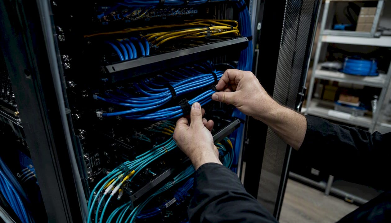
Do a targeted cleanup that removes abandoned cables, labels every active port, tests every run, and produces an as-built port map. The result is a telecom room that any technician can service without tribal knowledge, and that passes a formal inspection.
Start here — five immediate actions:
- Photograph the room before touching anything. Every rack face, every cable bundle, every patch panel.
- Tag suspected abandoned cables with a date and owner label. Do not pull anything until you have traced it.
- Check link and activity LEDs on every switch port to separate live runs from dead ones.
- Note any airflow blockages, overfull trays, or unlabeled fiber runs before you begin physical work.
- Pull the POPProbe cable-management audit checklist as your 37-item acceptance baseline. It covers labeling, routing, firestopping, termination quality, and performance testing in a single document.
Three standards and tools anchor every professional cleanup: the TIA-568 structured cabling family (the governing specification for copper and fiber performance), a Fluke Networks-class certifier for copper runs, and a tray-fill guideline that recommends keeping capacity available for future growth. Cables and Chips handles the full sequence for commercial clients across New York City.
Key Takeaways
A telecom room cleanup produces a verified, maintainable infrastructure only when it combines physical organization with certified testing, consistent labeling, and formal as-built documentation.
| Point | Details |
|---|---|
| Remove abandoned cables first | Tag, trace, and remove or manifest every dead run before reorganizing active cabling. |
| Label every port with a consistent scheme | A port map tied to switch ports, wall jacks, and cable types makes every future move faster. |
| Certify to TIA-568 standards | Copper runs need Fluke-level pass/fail results; fiber needs insertion-loss and OTDR data. |
| Keep tray fill below 80% | The POPProbe audit checklist flags a tray fill limit below full capacity as a planning guide for capacity and heat management. |
| Cables and Chips delivers the full package | Trace, remove, label, test, and as-built documentation with written client sign-off on every project. |
What should you do in the first 60 minutes to clean up telecom room cabling?
The first hour is about protection and evidence, not cleanup. Work done before you understand what is live and what is abandoned causes outages that take hours to diagnose.
Safety checklist before touching any cable:
- Confirm UPS and PDU states. Know which circuits are energized.
- Verify the room is locked and access is logged. Anyone entering a live telecom room during work should be documented.
- Wear ESD wrist straps when working near active switching equipment.
- Identify plenum-rated (CMP) versus riser-rated (CMR) cable before disturbing bundles near ceiling penetrations. Pulling CMR cable through a plenum space is a code violation.
- Check that all existing firestop penetrations are intact. Photograph any gaps.
Triage steps to collect baseline evidence:
- Photograph every rack, patch panel, and cable run from multiple angles.
- Inventory all active equipment: switches, routers, patch panels, ISP demarc, and UPS units.
- Use a handheld cable toner or a simple continuity tester to confirm which ports carry signal. LED activity checks on switch ports are fast but not conclusive on their own.
- Tag every suspected abandoned cable with a paper bag-and-tag label showing the date and the name of the person authorizing the tag. Do not remove until traced.
- Note any cooling blockages, overloaded trays, or cables routed across hot exhaust paths.
- Notify your IT team and building facilities manager before work begins. A single mislabeled pull can take a critical system offline.
Pro Tip: Take a short video walkthrough of the room before touching anything. A 90-second video captures spatial context that still photos miss, and it becomes your baseline evidence if a dispute arises later.
The 8-step process for a complete telecom room cleanup
A reproducible sequence matters because it protects both the technician and the client. Structured cleanup workflows that include site review, tracing, re-termination, labeling, testing, and port mapping consistently produce auditable deliverables. Here is the full sequence:
-
Discovery and photo documentation. Inventory every piece of rack-mounted equipment. Record switch model, port count, patch panel layout, ISP demarc location, and UPS capacity. This becomes the baseline for your as-built drawing.
-
Cable tracing and identification. Trace each run from its patch panel port to its wall jack or device. Mark active runs with green tape or a cable flag; mark suspected abandoned runs with red. Budget generously here. Field technicians consistently report that tracing unknown runs is the single most time-consuming task on any cleanup job, and accurate estimates must account for it before quoting hardware.
-
Remove or isolate abandoned cables. Once a run is confirmed dead, remove it cleanly or, if removal is not safe (e.g., the cable passes through a sealed firestop), bag-and-tag it with a date and owner, and document it in the removed-cable manifest. Abandoned cables block airflow, add weight to trays, and create confusion for every technician who works in the room after you.
-
Re-patch and bundle. Replace oversized patch cords with correct-length ones. Route cables through horizontal managers and use Velcro hook-and-loop straps for bundling. Avoid zip-ties on data cables. Zip-ties cinched too tightly deform the cable jacket and can degrade Cat6A performance by compressing the internal pair geometry.
-
Terminations and repairs. Re-punch or replace any damaged jacks, keystone modules, or patch panel ports. Follow TIA-568 punchdown color sequences (T568B is the US commercial standard) and verify each termination visually before testing.
-
Structured labeling and documentation. Apply a consistent labeling scheme to every port, patch panel position, and cable run. A port map ties each patch panel port to its switch port, wall jack ID, and room location. This is the foundation of your as-built documentation and the deliverable that makes future moves and changes fast.
-
Testing and certification. Run Fluke-level certification tests on every copper run. For fiber, perform visual inspection, light-source and power-meter checks, and OTDR traces on runs longer than 30 meters or any run that showed anomalies during cleanup. Record pass/fail results by port ID.
-
Final validation and client sign-off. Walk the client through the completed room. Present before/after photos, the port map, test logs, and the removed-cable manifest. Obtain written sign-off tied to measurable acceptance criteria.
| Step | Primary Output | Acceptance Metric |
|---|---|---|
| Discovery | Equipment inventory, baseline photos | All rack equipment documented |
| Tracing | Active/abandoned cable map | Every run classified |
| Removal | Removed-cable manifest | Zero untagged abandoned cables |
| Re-patch and bundle | Organized rack with correct-length cords | Velcro bundling, no zip-ties on data |
| Terminations | Repaired jacks and panels | Visual pass, no damaged ports |
| Labeling | Port map and cable schedule | Consistent scheme, every port labeled |
| Testing | Certified test report by port | Pass to Cat6/Cat6A or fiber spec |
| Sign-off | As-built package, client signature | Written acceptance obtained |
Which hardware and materials actually matter for telecom room organization?
Not all cable management hardware delivers equal value. These are the items that materially affect reliability and maintainability.
High-impact hardware:
- Ladder racks and cable trays route horizontal runs cleanly above or below the rack row. Cable trays should stay below 80% fill capacity to allow for future adds and to prevent heat buildup in dense bundles.
- Horizontal cable managers (1U or 2U) keep patch cords organized at the rack face and prevent the “waterfall” effect where cords drape over equipment.
- Vertical managers route cables between rack units without blocking adjacent equipment airflow.
- Brush panels provide a clean, flexible entry point for cables entering the rack from overhead or underfloor pathways.
- Strain-relief brackets protect terminations at patch panels and wall jacks from pull forces.
Consumables and standards:
- Use color-coded patch cords by function: blue for data, yellow for fiber, red for critical infrastructure, gray for standard voice. Consistency makes visual audits fast.
- Velcro hook-and-loop straps for bundling. They are reusable and do not compress cable jackets.
- Flame-rated jacket types matter. CMP (plenum) cable is required in air-handling spaces. CMR (riser) cable is the minimum for vertical runs between floors. Substituting CMR for CMP in a plenum space is a code violation and a fire hazard.
- Label stock rated for the environment. Thermal-transfer labels on polyester stock outlast paper labels in warm, humid telecom rooms.
Test equipment:
- A Fluke Networks DSX CableAnalyzer or equivalent certifier is the standard for Cat6/Cat6A copper certification. Renting one is practical for a single project; buying makes sense if your team runs more than a few cleanups per year.
- For fiber, an OTDR and a light-source/power-meter kit are the minimum. Visual fault locators help locate breaks in short runs.
- A basic cable toner and probe set handles continuity checks and tracing during the discovery phase.
Pro Tip: Keep a small remediation kit in the telecom room: six each of 1-foot, 3-foot, and 7-foot patch cords in your standard colors, plus a spare roll of Velcro and a pack of labels. Technicians doing moves and adds will use correct-length cords instead of grabbing whatever is nearby, and the room stays organized between formal cleanups.
What should you test after cleaning up the cabling?
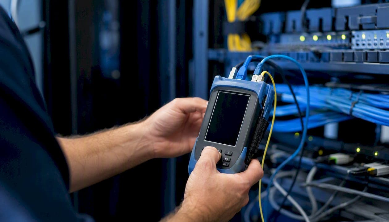
Testing converts a visual cleanup into a verified, documented infrastructure. Without test results tied to port IDs, you cannot prove performance or identify marginal terminations before they cause an outage.
Copper testing checklist:
- Wiremap: confirms correct pin-to-pin continuity and catches split pairs, reversed pairs, and shorts.
- Length: verifies the run does not exceed the 100-meter channel limit for Cat6/Cat6A.
- NEXT (Near-End Crosstalk) and attenuation: the core performance parameters for Cat6 and Cat6A certification.
- Return loss and insertion loss: required for full TIA-568 channel certification.
- Run every test to the applicable TIA-568 standard for the installed cable category.
Fiber testing checklist:
- Visual inspection of connectors with a fiber inspection scope before any connection.
- Insertion loss measured with a calibrated light source and power meter.
- OTDR trace for runs longer than 30 meters, any run with a splice, or any run that failed insertion-loss testing.
Sample test-report fields for the deliverables package:
| Field | Description |
|---|---|
| Port identifier | Patch panel number and port position |
| Wall jack ID | Room number and jack label |
| Switch port | Switch hostname and port number |
| Test type | Cat6 channel, Cat6A channel, or fiber insertion loss |
| Measured result | Key parameter value (e.g., NEXT margin) |
| Pass/Fail | Result against TIA-568 limit |
| Technician sign-off | Name and date of test |
Common failure modes and what they mean:
- Marginal NEXT or return loss: usually a poor punchdown at the jack or patch panel. Re-terminate and retest.
- Split pair: wires from two different pairs crossed at a termination. Rewire to T568B.
- Excessive length: the run exceeds 100 meters. Requires a relay point or a shorter routing path.
- High fiber insertion loss: dirty or damaged connector. Clean with an IEC 61300-3-35-compliant kit and reinspect before retesting.
How do you keep a telecom room code-safe and compliant?
Compliance is not optional. A telecom room that fails a fire inspection or causes an outage due to blocked airflow creates liability that far exceeds the cost of doing the work correctly.
Firestopping and cable jacket requirements:
- Every cable penetration through a fire-rated wall or floor must be sealed with listed firestop material after the cleanup. Photograph each penetration before and after sealing.
- CMP (plenum) cable must be used in any air-handling space. CMR (riser) cable is the minimum for vertical shafts. Never substitute a lower-rated jacket to save cost.
- Document cable types by zone in the as-built drawing so future contractors know what they are working with.
Airflow and rack layout:
- Route cables away from equipment inlet and exhaust faces. A cable bundle draped across a switch’s exhaust port raises operating temperature and shortens hardware life.
- Maintain clearance around CRAC or CRAH units. Blocked return-air paths reduce cooling efficiency across the entire room.
- Use blanking panels in empty rack units to prevent hot-aisle air from recirculating to the cold aisle.
Capacity management:
The POPProbe cable-management audit checklist covers 37 inspection items and explicitly calls out 80% tray fill as a planning guideline. Keeping trays below that threshold preserves room for future adds and prevents heat buildup in dense bundles.
Access control:
- The telecom room must be locked, with access logged. Any work involving live circuits requires documented authorization.
- Include a sign-off requirement for any cable removal or re-termination in the project scope of work.
When should you hire a professional, and what should they deliver?
Some cleanups are manageable with internal IT staff. Others require a licensed low-voltage contractor with test equipment, documented methodology, and liability coverage.
Hire a professional when:
- The room has a large number of orphaned or untraced runs and no existing documentation.
- Mixed cable types (Cat5e, Cat6, fiber, coax) are present in critical spaces without clear labeling.
- Certification testing has failed and the root cause is unknown.
- A security audit, lease renewal, or compliance review requires formal documentation.
- Internal staff lack a Fluke-class certifier or fiber test equipment.
Deliverables to require in the scope of work:
- Before/after photo documentation of every rack and cable pathway.
- Port-by-port test reports tied to TIA-568 pass/fail criteria.
- As-built drawings showing rack layout, cable routes, and port assignments.
- A cable schedule listing every active run by port ID, destination, cable type, and length.
- A removed-cable manifest documenting every abandoned cable pulled or tagged.
- Labeled patch panels with a consistent, documented scheme.
- A client walkthrough and written sign-off at project completion.
Typical project scope and effort:
| Project Size | Scope | Technician-Days | Lead Time |
|---|---|---|---|
| Small (1 closet, under 50 ports) | Trace, label, test, document | 1–2 days | 1–2 weeks |
| Medium (2–4 closets, 50–200 ports) | Full cleanup, re-termination, certification | 3–5 days | 2–4 weeks |
| Large (MDF + multiple IDFs, 200+ ports) | Full remediation, fiber, as-built drawings | 1–3 weeks | 4–8 weeks |
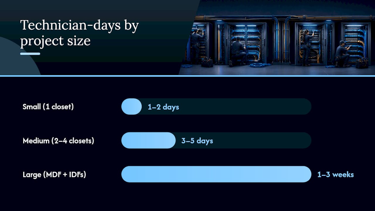
Cost drivers: tracing time dominates labor cost on disorganized rooms. Hardware replacement (patch panels, managers, racks) is a secondary driver. Fiber work adds cost due to test equipment and splice labor. A project-based SOW with fixed deliverables protects both parties better than open-ended hourly billing.
Pro Tip: Require that the vendor’s acceptance criteria reference specific, measurable test results. A proposal that promises “clean and organized” without a test-report deliverable gives you no contractual basis for rejection if the work is substandard.
A Cables and Chips telecom room cleanup: scope and outcomes
A commercial office in Lower Manhattan contacted Cables and Chips after a network audit flagged undocumented runs, failed Cat6 certification on several ports, and a patch panel with no labeling. The room had accumulated cabling from three separate tenant buildouts over roughly a decade.
Remediation steps performed:
- Full room photography and equipment inventory before any work began.
- Cable tracing of all 84 runs. Thirty-one were confirmed abandoned and removed. Six required re-termination to resolve wiremap failures.
- Replacement of two damaged patch panels and installation of horizontal cable managers on all four rack units.
- Velcro bundling of all active runs, color-coded patch cords applied by function.
- Cat6 channel certification of all 53 active copper runs using a Fluke Networks DSX CableAnalyzer. All passed TIA-568-C.2 limits.
- As-built drawing produced showing rack layout, port assignments, and cable routes to each wall jack and device.
Deliverables provided to the client:
- Before/after photo set (rack face, cable pathways, patch panels).
- Port-by-port test report with pass/fail results and technician sign-off.
- Removed-cable manifest listing all 31 abandoned runs with location and disposal date.
- Labeled patch panels with a printed port map posted inside the rack door.
- Client walkthrough and written sign-off.
The benefits of clean cable management extend beyond aesthetics. A documented, tested infrastructure reduces mean time to repair because any technician can trace a fault without relying on institutional memory. Faster device provisioning follows from labeled ports and a current port map. One healthcare system cleanup tracked by Datasource Technology reported a 30% reduction in wireless-related support calls and a 45% improvement in Wi-Fi coverage scores after a structured IDF/MDF remediation, demonstrating the operational gains that rigorous closet cleanup produces.
Recommended maintenance cadence:
- Monthly visual checks: confirm no new unlabeled cables, no airflow blockages, no loose patch cords.
- Annual re-certification of critical links, particularly any runs supporting VoIP, wireless access points, or security systems.
What field experience teaches you about telecom room cleanups
The surprises that derail cleanup projects are almost always the same ones. Hidden abandoned runs that were never documented because the original contractor left without producing as-builts. Patch panels labeled in a scheme only one person understood, and that person left the company two years ago. Cable bundles so large and tightly packed that heat buildup was measurable on the jacket surface.
The handoff between IT and facilities is where scope creep lives. IT wants to add new runs while the room is open. Facilities wants to repaint or reconfigure the rack layout. Both are reasonable, but neither belongs in a cleanup SOW unless it was scoped and priced upfront. A signed acceptance package tied to specific test results and as-built deliverables is the only thing that closes a project cleanly. Without it, “done” means different things to different people, and the contractor gets called back for work that was never in scope.
The other thing field experience teaches: the network closet organization work that looks purely cosmetic is actually the work that prevents the 2 AM outage call. A labeled, tested, documented room is a room where faults are found in minutes, not hours.
Cables and Chips brings 40+ years of structured cabling expertise to your cleanup
A telecom room cleanup done right produces a tested, labeled, documented infrastructure that any technician can service on day one. Cables and Chips delivers exactly that for commercial offices and secure facilities across New York City: cable tracing, abandoned-cable removal, re-termination, Cat6/Cat6A certification, fiber testing, as-built documentation, and client sign-off on every project.

With more than 40 years of low-voltage contracting experience, Cables and Chips brings the test equipment, the methodology, and the documentation discipline that turns a disorganized telecom room into a verified, maintainable asset. Every project includes a written SOW with measurable acceptance criteria, a port-by-port Cat6 certification report, and a complete as-built package at handoff.
Request a site survey to get a scoped proposal with fixed deliverables. Call Cables and Chips at 20 Vesey Street, Lower Manhattan, or visit Cables to schedule a project scoping call.
Sources
- Cable Management Audit Checklist FREE PDF FREE | POPProbe
- Clean Closets, Clear Signals: The Hidden Power of IDF/MDF Optimization – Datasource Technology
FAQ
How long does it take to clean up a telecom room?
A single closet with fewer than 50 ports typically takes 1–2 technician-days. Medium projects covering 2–4 closets and up to 200 ports run 3–5 days. Large MDF/IDF remediations with fiber and full as-built documentation can take 1–3 weeks.
What is the difference between a cleanup and a structured cabling installation?
A cleanup organizes, tests, and documents existing infrastructure without necessarily replacing it. A structured cabling installation builds a new, standards-compliant physical layer from scratch. Many cleanups reveal termination failures or capacity gaps that lead to a partial reinstall.
Do you need to test cables after a telecom room cleanup?
Yes. Visual organization without certified test results leaves marginal terminations and split pairs undetected. TIA-568 channel certification confirms that every active run performs to its rated category, and the test report becomes a contractual deliverable tied to acceptance.
When should you hire a contractor instead of doing the cleanup in-house?
Hire a contractor when the room has untraced abandoned runs, failed certification results, mixed cable types without documentation, or when a compliance audit requires formal as-built deliverables. Cables and Chips provides a written SOW with measurable acceptance criteria for every commercial cleanup project in New York City.
What deliverables should a cabling contractor provide after a cleanup?
At minimum: before/after photos, a port-by-port test report with pass/fail results, an as-built drawing, a cable schedule, a removed-cable manifest, and written client sign-off. Any proposal that omits test reports or as-built documentation is incomplete.