

CCTV Cabling Plan for Secure Facilities: 2026 Guide

TL;DR:
- A CCTV cabling plan for secure facilities must comply with standards like TIA-568-E and NIST 800-53 PE-4. Proper grounding, physical security measures, and fiber optic boundaries help prevent signal interception and electromagnetic leakage. Detailed documentation and correct certification testing ensure system reliability, security, and regulatory compliance.
A CCTV cabling plan for a secure facility is defined as the structured layout, cable specifications, and network architecture that supports every camera in a monitored environment. Getting this right means meeting TIA-568-E copper channel limits, satisfying NIST 800-53 PE-4 physical security controls, and building an infrastructure that performs reliably for years. Most security professionals treat CCTV as low-voltage work. The facilities that get it wrong pay for that assumption with failed certifications, signal loss, and compliance gaps. A well-designed surveillance system cabling plan is enterprise IP infrastructure first, and physical security second.
What are the essential standards for CCTV cabling in secure facilities?
The TIA-568-E standard sets the copper channel length limit at 100 meters total: 90 meters of horizontal cabling plus 10 meters of patch cords. Cat6A is required for 10GBASE-T and PoE++ applications in secure facilities. That limit is not a guideline. Exceeding it without adding a switch or converting to fiber means your cameras will drop frames or lose connectivity entirely.
NIST 800-53 PE-4 mandates physical protection of all transmission media. The control requires locked wiring closets, cable housing in conduit or cable trays, and the disabling of all unused network jacks. These are baseline requirements for federal environments and any facility that handles sensitive operations. Ignoring PE-4 is not a technical oversight. It is a compliance failure.
For highly sensitive spaces such as SCIFs and secure conference rooms, TEMPEST-aligned measures go further than physical locks. Shielded cabling and acoustic isolation are required to prevent compromising electromagnetic and acoustic emanations. Most installers never think about this. In classified spaces, it is the difference between a compliant installation and a security breach.
The network layer carries equal weight. Enterprise-grade CCTV systems require managed Layer 2+/Layer 3 switches with VLAN segmentation to isolate camera traffic from general IT traffic. Unmanaged switches and open port forwarding create vulnerabilities that no physical lock can fix.
- Use Cat6A for all horizontal runs supporting PoE++ cameras
- Require managed switches with VLAN segmentation on every camera network
- Lock all wiring closets and disable unused jacks per PE-4
- Apply TEMPEST shielding requirements in classified or sensitive rooms
- House all cabling in conduit or cable trays, never open tray in secure zones
Pro Tip: Treat every unused RJ-45 jack in a secure facility as an open door. Disable it in the switch configuration and install a physical port lock. PE-4 compliance requires both.
How do you plan and map CCTV cable routes and network architecture?
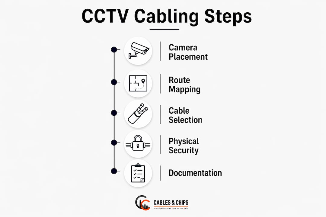
Camera count and placement drive every routing decision. Start with a floor plan and mark every camera location based on coverage requirements, blind spots, and lighting conditions. Each camera location becomes a cable endpoint, and every endpoint needs a path back to a wiring closet or intermediate distribution frame (IDF).

Large facilities benefit from a three-tier network design. Access switches sit at the camera edge, aggregation switches consolidate traffic from multiple access switches, and core switches connect to the control center and NVR storage. This three-tier architecture supports fault isolation and makes future expansion straightforward. A single flat network with one switch serving 60 cameras is a single point of failure.
Physical routing requires discipline. Run camera cabling in dedicated conduit or cable trays, separated from power wiring by at least 12 inches to avoid electromagnetic interference. Where cable paths cross power runs, cross at 90-degree angles. Plan routes that minimize total cable length while keeping runs within the 90-meter horizontal limit. For a practical overview of how this process works on commercial sites, see how security camera cabling is planned in real-world builds.
Documentation is not optional. Every cable run needs a label at both ends, a record in your floor plan, and an entry in your IP address scheme. Comprehensive CCTV network documentation of IP schemes, labeling, and physical routing diagrams is as critical as the physical installation itself. Without it, a single technician departure can leave your team unable to troubleshoot or expand the system.
| Planning Step | Key Requirement | Standard/Reference |
|---|---|---|
| Camera placement | Coverage map with no blind spots | Facility security policy |
| Network topology | Three-tier access/aggregation/core | CCTV network architecture best practices |
| Cable routing | Dedicated conduit, 90m horizontal max | TIA-568-E |
| Physical security | Locked IDFs, conduit in sensitive zones | NIST 800-53 PE-4 |
| Documentation | Labeled cables, IP scheme, floor plan | IT/security operational standards |
Pro Tip: Number every camera on your floor plan before pulling a single cable. Assign each camera a port on a specific switch, and document that mapping before installation begins. Retrofitting documentation after the fact costs three times as long.
What are the best practices for selecting cables and equipment?
Cat6A is the correct choice for horizontal runs in any facility running high-resolution IP cameras with PoE. Cat6 handles PoE+ but struggles with PoE++ heat dissipation over long runs. Cat6A’s larger conductor and tighter shielding handle both the bandwidth and the thermal load. Every horizontal run must pass Permanent Link testing per TIA-568 before the project is certified. That test excludes patch cords and measures only the installed cabling, which is the installer’s direct responsibility.
Fiber optic backbone cabling is the right choice for runs exceeding 90 meters, for inter-building connections, and for any path crossing areas with heavy electrical equipment. Fiber eliminates electromagnetic interference entirely and breaks the electrical conduction path between buildings. For facilities weighing this decision, the Cat6A vs. fiber comparison covers the performance and compliance trade-offs in detail.
Switch selection matters as much as cable selection. Maintain a 20–30% PoE headroom in your switch power budget to support high-resolution IR cameras and cameras with built-in heaters. A switch running at 95% PoE capacity will drop cameras when ambient temperature rises or when a camera cycles its heater. That is a preventable failure.
- Use Cat6A for all horizontal camera runs
- Use fiber for backbone runs and inter-building segments
- Maintain 20–30% PoE headroom on every switch
- Match connector category to cable category: Cat6A cable requires Cat6A-rated jacks and patch panels
- Use shielded Cat6A (F/UTP or S/FTP) in TEMPEST-sensitive areas
- Never exceed the manufacturer’s minimum bend radius during installation
BICSI installation standards are clear: poor installation practices such as incorrect bend radius, excessive cable untwisting at terminations, or mismatched connectors cause certified Cat6A cable to fail performance tests. The cable category on the box means nothing if the installation quality does not match it.
How do you implement physical and signal security in CCTV cabling?
Physical safeguards form the first layer of a compliant CCTV infrastructure design. Every wiring closet and IDF must be locked, with access logged and restricted to authorized personnel. Conduit must be EMT or rigid metal in SCIF-grade installations. Simple plastic conduit or open cable trays do not meet PE-4 requirements. Tamper-evident junction boxes at camera locations add a second layer of detection for any physical interference attempt.
Signal security addresses a threat most facility managers never consider. Copper cabling conducts both electrical signals and acoustic vibrations. In a sensitive conference room or secure operations center, a copper cable running through the wall can act as a microphone pickup. The solution is to install fiber optic media converters at the boundary of every secure room. Fiber does not conduct vibrations or electrical signals, which eliminates the galvanic microphone effect entirely.
Conduit penetrations through walls and floors require sealing with acoustic and fire-rated compounds. An unsealed conduit penetration defeats both the acoustic isolation and the fire rating of the wall assembly. This step is consistently skipped on installations that were never designed with TEMPEST compliance in mind.
Physical protection of transmission media is a baseline control under NIST 800-53 PE-4. In high-security zones, that baseline extends to shielded cabling, sealed conduit penetrations, and fiber optic isolation at room boundaries. Meeting the letter of PE-4 without addressing acoustic and electromagnetic emanations leaves classified spaces exposed to threats that physical locks cannot stop.
The full sequence for signal-secure CCTV cabling looks like this:
- Run all cabling in EMT or rigid metal conduit within secure zones
- Install fiber optic media converters at every secure room boundary
- Seal all conduit wall and floor penetrations with acoustic and fire-rated compound
- Disable and physically lock all unused network jacks
- Apply shielded Cat6A (F/UTP or S/FTP) inside TEMPEST-sensitive areas
- Document every penetration, seal, and media converter location in the as-built drawings
For facilities that also manage access control alongside CCTV, the access control cabling requirements guide covers complementary physical security controls that integrate with this cabling framework.
What are common mistakes in CCTV cabling plans and how do you fix them?
The most expensive mistake in surveillance system cabling is confusing Permanent Link testing with Channel testing. Permanent Link testing isolates the installed cabling from patch cords, giving a clear result that the installer owns. Channel testing includes patch cords, which means a failing patch cord can mask a cabling defect or vice versa. Require Permanent Link certification on every project. It is the only test that accurately reflects the installer’s work.
Exceeding the 90-meter horizontal cable limit is the second most common error. Facilities with large floor plates often push runs to 110 or 120 meters without adding intermediate switches or converting to fiber. The result is intermittent connectivity and PoE instability that is difficult to diagnose without a cable certifier. The fix is straightforward: add an IDF or convert the long run to fiber before installation, not after.
Mismatched connectors are a silent failure mode. A Cat6A cable terminated with a Cat6 jack will not pass Cat6A certification. The channel is only as good as its weakest component. This error is common when installers pull from mixed inventory on large projects.
- Neglecting physical security around cabling: unlocked IDFs and open trays are PE-4 violations
- Skipping as-built documentation: undocumented segments become orphaned infrastructure within 18 months
- Using unmanaged switches: they create security vulnerabilities and make VLAN segmentation impossible
- Ignoring PoE headroom: running switches above 70% PoE capacity causes thermal and power instability
- Failing to seal conduit penetrations: this defeats both acoustic isolation and fire ratings
Pro Tip: Schedule a cable certification walkthrough before drywall closes. Fixing a failed Permanent Link test after walls are sealed costs significantly more than catching it during rough-in.
Maintenance keeps a certified system certified. Label every cable at both ends with a consistent naming convention tied to your floor plan. Inspect conduit seals and junction box tamper indicators annually. Re-test any cable that has been disturbed during a renovation. Structured cabling as-built documentation should be updated every time a cable is added, moved, or removed.
Key Takeaways
A compliant CCTV cabling plan for a secure facility requires Cat6A horizontal cabling, NIST 800-53 PE-4 physical controls, fiber optic signal isolation at room boundaries, and complete as-built documentation to maintain system integrity and certification.
| Point | Details |
|---|---|
| Cat6A is the baseline cable | Use Cat6A for all horizontal runs supporting PoE++ cameras and 10GBASE-T switches. |
| PE-4 controls are mandatory | Lock wiring closets, disable unused jacks, and house cabling in EMT conduit in secure zones. |
| Fiber breaks signal paths | Install fiber optic media converters at secure room boundaries to eliminate acoustic and galvanic threats. |
| Permanent Link testing is required | Certify every installed run with Permanent Link testing per TIA-568-E, not Channel testing. |
| Documentation sustains compliance | Maintain labeled cables, IP schemes, and floor plan records updated after every change. |
Why most CCTV cabling projects underestimate what “secure” actually means
I have reviewed a lot of CCTV cabling plans over the years, and the pattern is consistent. The cable type is usually right. The camera count is usually right. What is almost always wrong is the assumption that physical locks and conduit are enough.
The acoustic emanation problem is real and widely ignored. Copper cabling running through a secure conference room wall can pick up vibrations from conversations inside that room and transmit them as electrical signals on the cable. Most installers have never heard of this. Most facility managers have never been told about it. But if your facility handles sensitive conversations or classified operations, this is not a theoretical risk.
The second thing I see consistently underestimated is documentation. Teams spend months planning the physical installation and then produce as-built drawings that are out of date within six months. Every undocumented cable segment is a liability. When a camera goes offline at 2:00 AM and the technician cannot find the cable run on any drawing, the documentation failure becomes an operational failure.
The third gap is the IT and security coordination problem. CCTV cabling must integrate into overall network management and documentation to avoid orphaned or undocumented segments. Security teams design the camera layout. IT teams manage the switches. Facilities teams manage the conduit and closets. When those three groups do not coordinate from the start, you get a system where nobody owns the full picture.
Treat your CCTV infrastructure the way you treat your core network. Specify the same cable categories, require the same certification testing, demand the same documentation standards, and apply the same physical security controls. Your network is only as strong as the infrastructure behind it.
— Ken
Cables and Chips builds CCTV cabling infrastructure that meets the standard
Cables and Chips designs and installs CCTV and access control cabling for commercial offices, secure facilities, and enterprise environments throughout New York City. Every project includes Cat6A or fiber optic installation, Permanent Link certification testing, and complete as-built documentation aligned with TIA-568-E and NIST 800-53 PE-4 requirements.

With more than 40 years of experience in low voltage and structured cabling, Cables and Chips delivers installations that are tested, labeled, and documented from day one. Facility managers and security professionals can review the full range of structured cabling system components and service options, or contact Cables and Chips directly to schedule a site survey for your facility.
FAQ
What cable type is required for CCTV in secure facilities?
Cat6A is required for horizontal runs supporting PoE++ cameras and 10GBASE-T switches, per TIA-568-E standards. Fiber optic cabling is required for backbone runs exceeding 90 meters or crossing areas with heavy electrical interference.
What does NIST 800-53 PE-4 require for CCTV cabling?
PE-4 mandates locked wiring closets, cabling housed in conduit or cable trays, and all unused network jacks disabled and physically locked. In SCIF-grade installations, conduit must be EMT or rigid metal with sealed penetrations.
What is Permanent Link testing and why does it matter?
Permanent Link testing certifies the installed horizontal cabling independently from patch cords, giving a clear result that reflects the installer’s work. It is the correct certification method under TIA-568-E and prevents misdiagnosed faults caused by failing patch cords masking cabling defects.
How do fiber optic media converters improve signal security?
Fiber optic media converters at secure room boundaries eliminate the galvanic microphone effect by breaking the electrical conduction path. Fiber does not conduct vibrations or electrical signals, which removes the risk of acoustic emanations traveling out of the room on copper cabling.
How should CCTV cabling be documented for compliance?
Every cable run requires a label at both ends, a record in the floor plan, and an entry in the IP address scheme. As-built documentation must be updated after every change and should include physical routing diagrams, switch port assignments, and conduit penetration records.