
Cat6 Bend Radius: The Minimum Every Installer Should Know
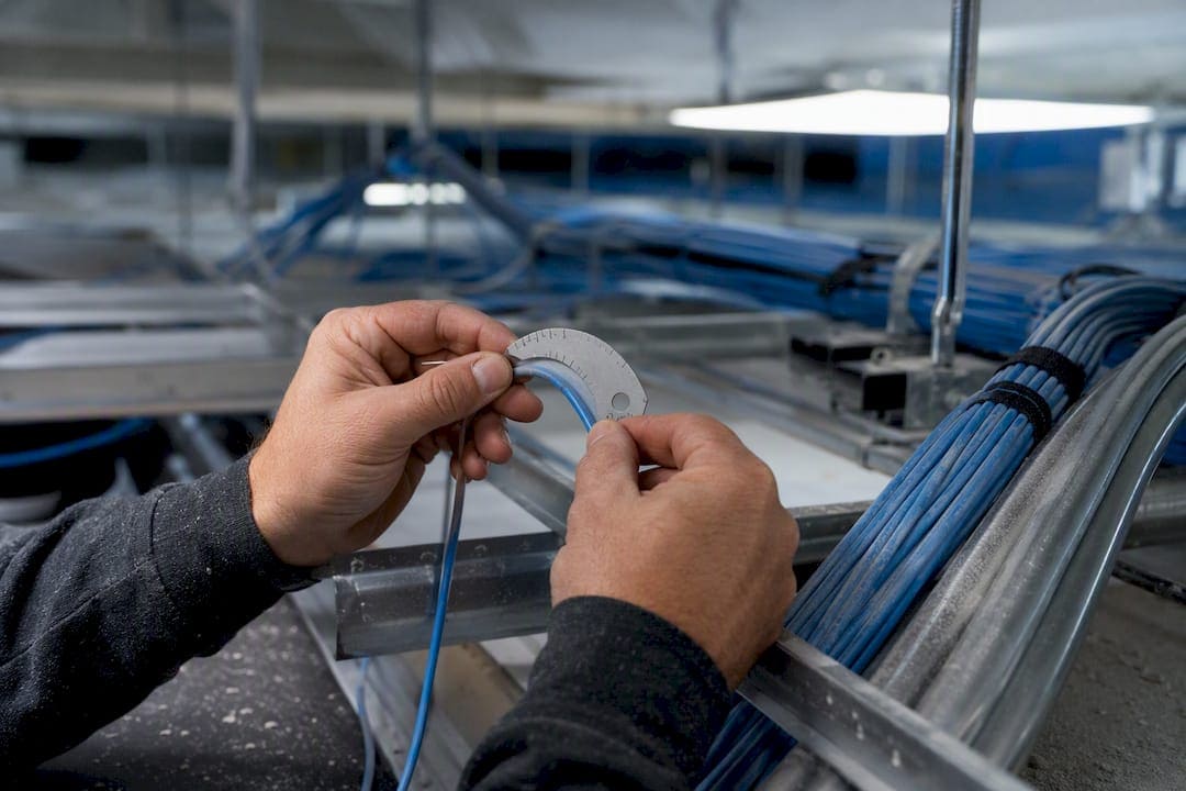
For standard 4-pair Cat6 cable, the minimum bend radius is four times the cable’s outer diameter (4× OD), and that limit applies both during the pull and after the cable is at rest. Shielded constructions, cables under tension, and some Cat6A designs require a larger multiplier, typically around 8× OD depending on the manufacturer’s datasheet. Exceeding this limit can cause permanent geometry damage inside the cable, pair twists distort, and the link may experience NEXT and attenuation failures that a certifier will detect even when the jacket looks fine.
Here’s the quick math: a Cat6 cable with a typical outer diameter needs a bend radius of at least four times that diameter, measured to the inside of the curve.
- Standard rule: 4× OD for unshielded 4-pair Cat6 and Cat6A
- Tensioned or shielded exception: 8× OD, per manufacturer guidance
- Consequence of violating it: permanent pair distortion, elevated NEXT, reduced usable bandwidth
- Quick example: 0.25" OD × 4 = 1.0" minimum radius
TL;DR:
- Cat6 cables require a minimum bend radius of four times their outer diameter for standard installations, with shielded or tensioned cables needing up to eight times according to manufacturer guidance.
- Proper support spacing and continuous supports are crucial to maintaining the correct bend radius and preventing pair distortion that can cause future certification failures.
- Visual inspection alone cannot detect subtle pair geometry damage caused by bends; certifier tests like NEXT, return loss, and insertion loss are essential for verifying integrity.
- Support quality, support spacing, and careful pathway design are more important than avoiding obvious corners in preventing long-term cable damage.
- Following industry standards and documenting support and testing results from the start reduces costly rework and ensures long-term cable reliability.
What Determines Cat6 Bend Radius Requirements?
The 4× OD rule isn’t arbitrary. It comes directly from the ITS Installation Methods Manual published by BICSI, which aligns with ANSI/TIA-568 guidance for 4-pair balanced twisted-pair cable. The standard sets 4× OD as the baseline for cable at rest and during installation, then raises that multiplier to 8× OD when the cable is under pulling tension or built with certain shielded constructions.
Category number alone doesn’t tell you the bend radius. A Cat6A cable is thicker than Cat6 because of the extra shielding or spacing needed to control alien crosstalk, so its actual outer diameter, not its category label, is what drives the calculation. Two Cat6 cables from different manufacturers can carry different OD specs depending on jacket thickness, conductor gauge, and whether the construction is stranded (patch cord) or solid (horizontal run).
Several factors affect the required radius beyond the base multiplier:
- Shielding: Shielded twisted pair (F/UTP or S/FTP) often needs a larger multiplier because the foil or braid resists bending without cracking.
- Jacket rating: Plenum-rated jackets tend to be stiffer than riser or PVC jackets, which changes how the cable tolerates a tight curve.
- Conductor type: Stranded patch cords flex more forgivingly than solid-conductor horizontal cable, but both still have a hard minimum.
- Tension state: Any cable under pulling load during installation needs the larger multiplier, since tension combined with a tight bend compounds stress on the pairs.
Manufacturer datasheets override generic rules whenever they conflict. Always check the job spec and the cable reel’s actual documentation before assuming 4× OD applies universally.
How Do You Calculate Minimum Bend Radius for Cat6?
The formula is straightforward: minimum bend radius = cable OD × multiplier. Measure the outer diameter in inches or millimeters, apply 4× for standard unshielded runs, and use 8× for shielded or tensioned installations unless the manufacturer specifies otherwise.

Most Cat6 patch cords run around 0.21 inches (5.3 mm) OD, while horizontal Cat6 cable typically measures closer to 0.25 inches (6.4 mm), and these differences change your minimum radius meaningfully across a jobsite full of cable types, according to industry installation guides.
To convert millimeters to inches in the field, divide by 25.4 and round up slightly rather than down. A cable measuring 6.5 mm OD comes to 0.256 inches. Multiply that by 4 for 1.02 inches, and round up to 1.0625 inches (17/16 inch) if you’re marking a bend template with a tape measure.
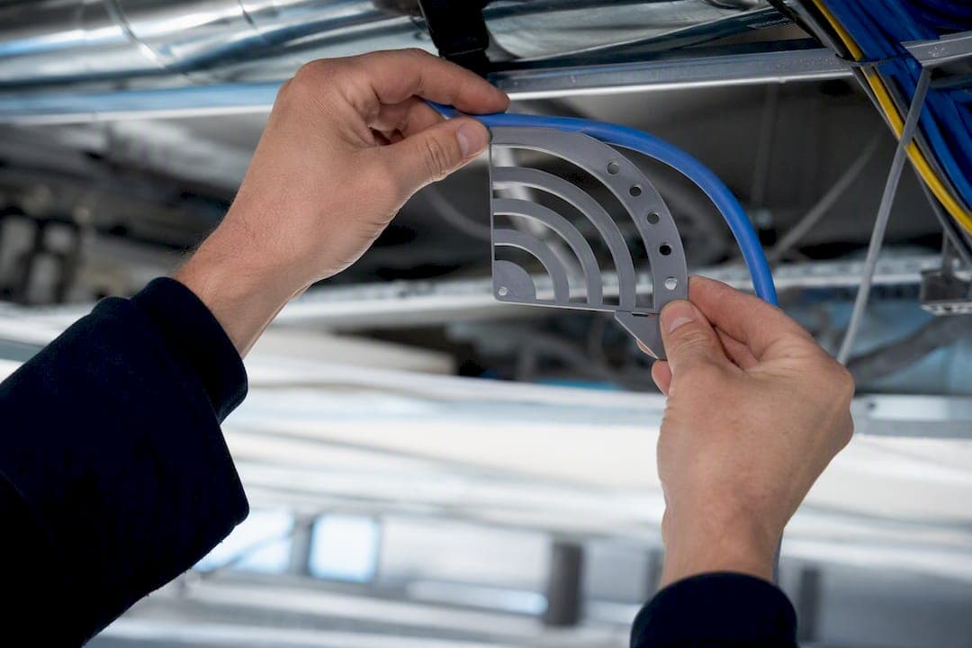
Pro Tip: Carry a small radius gauge or 3D-print a set of common radius templates (0.75", 1.0", 1.5", 2.5") for your tool bag. Eyeballing a bend under fluorescent lighting in a ceiling cavity is how installers convince themselves a bend “looks fine” when it isn’t.
How Do You Preserve Bend Radius During Installation?
Bend radius violations rarely happen at the obvious 90-degree corner. They happen at the pinch points nobody notices: a cable draped over a sharp conduit edge, a J-hook spaced too far from the next one, or a bundle cinched down with a zip tie pulled too tight against a stud.
Follow this sequence on every run:
- Design the pathway before you pull cable. Route around sharp architectural corners and plan gentle sweeps at every direction change, especially where cable drops from a ceiling into a rack.
- Choose continuous supports over narrow hangers. Cable tray and continuous J-hook runs distribute the cable’s weight evenly, while widely spaced or undersized hooks create a hammock effect that bends the cable sharper than the hook itself.
- Verify J-hook and support specs. Manufacturer testing on the nVent CADDY Cat HP system found that many non-continuous supports indent the jacket and fail to preserve a 4× OD radius, while supports engineered for this purpose measured above the 4× threshold in the same tests.
- Space supports according to code and spec, not convenience. Wider gaps between supports let gravity pull the cable into a tighter sag than the rated radius allows.
- Install radius guards or bend-limiting grommets at terminations. Patch panels, wall plates, and rack entry points are where cables get crushed against a sharp metal edge during dressing.
- Pull with steady, controlled tension. Sudden jerks or pulling around a tight corner without a sheave or roller can combine tension and bend stress in a way that permanently damages pair geometry.
Pro Tip: When running cable through a bundle of J-hooks, check the hook closest to a 90-degree turn first. That’s almost always where the tightest, most damaging bend hides, and it’s the easiest one to miss during a final walkthrough.
What Field Tests Reveal Bend-Related Cable Damage?
Visual inspection catches the obvious problems: creases in the jacket, visible kinks, flattened sections where a cable was crushed against a stud, or a zip tie cinched so tight it left a permanent indentation. Walk every run before closing up ceilings or walls and look specifically for these signs at every direction change.
Visual checks alone aren’t enough, though. Pair geometry distortion from a bend violation often doesn’t show on the jacket at all, and the only reliable way to confirm it is a certifier test:
- NEXT (Near-End Crosstalk): A degraded NEXT reading at a specific distance on the cable often correlates with a bend or pinch point at that location.
- Return loss: Sharp bends create impedance mismatches that show up as return loss failures.
- Insertion loss: Excessive attenuation across the link can indicate cumulative bend damage along the run, not just one bad spot.
If a certifier flags a marginal or failing result, testing the run properly before signing off saves a callback later. Standards-based BICSI installation guidance treats certification testing as the definitive check for geometry integrity, since visual inspection catches gross problems but misses subtle NEXT increases. If a run fails and you can trace it to a known pinch point, re-route that section rather than accepting a marginal pass. Document any deviation you do accept, with the reason, in the as-built record.
What Mistakes Cause Long-Term Cat6 Reliability Problems?
Most bend-radius failures trace back to a handful of repeat offenses. Sharp bends right at the connector or patch panel are the most common, usually because the installer left too little slack to dress the cable properly. Poor support selection runs a close second: unsupported cable sagging between widely spaced hooks stretches beyond its rated radius even without a visible corner.
Conduit overfill compounds the problem by forcing cables into unnatural bends as they’re crammed through a full sleeve. Improper terminations, where a cable is bent sharply to reach a jack or port, finish the list.
- Sharp bends at connectors: Leave adequate service loop before terminating.
- Poor or absent support: Sagging cable violates radius even without a corner.
- Conduit overfill: Forces cables into unplanned bends under pressure.
- Improper termination angles: Bending cable sharply to reach a jack stresses the pairs right at the point of connection.
Each of these produces the same underlying failure: distorted pair geometry that raises NEXT, and in PoE deployments, jacket compression at pinch points can also trap heat around the conductors. Catching these issues starts with spec review, correct support selection, and honest as-built documentation.
What Ken Has Learned From Bend Radius Failures on the Job
Ken has spent decades running structured cabling projects across New York City commercial buildings with Cables and Chips, and one lesson repeats across almost every job: bend radius failures are support failures, not pulling failures.
On one commercial buildout, a previous contractor had used narrow, widely spaced J-hooks through a ceiling run above a conference room. Every cable sagged into a soft U-shape between hooks, well past the rated radius, and NEXT failures showed up on nearly a third of the run during certification. Swapping to continuous, properly spaced supports and re-pulling the affected runs eliminated the failures entirely, with no cable replacement needed.
Specify support type and spacing in writing, and photograph pathway conditions before ceiling tiles go back up.
Why Field Discipline Beats the Textbook Rule
The 4× OD rule is easy to memorize and easy to ignore in practice, which is exactly the gap that causes most real-world failures. Plenty of technicians can recite the multiplier but still route cable over a sharp conduit lip because it’s faster than adding a sweep fitting, or trust a bundle of thin J-hooks because that’s what was already mounted in the ceiling.
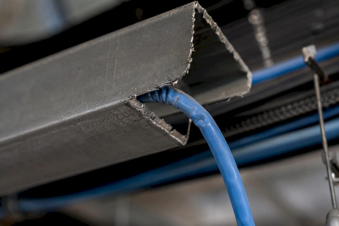
The standards documents don’t spend much time on pinch points, and that’s the conventional advice’s biggest blind spot. A cable can clear a 90-degree corner with room to spare and still fail certification because it sagged into an unsupported span for six feet, distorting the pair geometry gradually rather than at one obvious bend. Technicians trained to eyeball a single sharp corner miss this failure mode constantly.
What actually matters, based on how these failures show up in certifier results, is support consistency across the entire run, not just avoiding the dramatic 90-degree turn everyone was warned about in training. Prioritize continuous support and honest as-built notes over chasing a clean visual inspection, since the jacket rarely tells you the truth about what’s happening to the pairs inside it.
— Ken
Get Cabling Installed Right the First Time
Bend radius violations are cheap to prevent and expensive to fix once ceilings close and racks fill up, especially on a commercial buildout where a single failed certification run means opening walls back up. Cables and Chips designs pathways, selects supports, and pulls cable to meet TIA and BICSI specifications from day one, so you’re not chasing intermittent NEXT failures six months after occupancy.

Our teams handle everything from pathway design through final certification on structured Cat6 and Cat6A installations across New York City, with documentation practices that hold up if a dispute over installation quality ever comes up. Every project closes out with an as-built documentation package that records support types, pathway routes, and test results, so your facilities team has a real record instead of a guess. If you’re planning a commercial cabling project or inheriting a building with questionable existing infrastructure, request a site survey and specification review before the next phase of work begins.
Key Takeaways
Cat6 bend radius fails when installers ignore support consistency along the run, not just the sharp corners everyone’s trained to spot.
| Point | Details |
|---|---|
| Know the baseline multiplier | Minimum bend radius equals 4× the cable’s outer diameter for standard 4-pair Cat6 and Cat6A. |
| Watch for the 8× exception | Shielded constructions and cables under pulling tension often require 8× OD per manufacturer specs. |
| Calculate before you pull | A 0.25-inch OD cable needs at least a 1.0-inch radius; measure OD first, then multiply. |
| Support choice matters more than corners | Continuous or tested supports prevent sagging pinch points that violate radius without a visible bend. |
| Test to confirm, don’t just look | NEXT, return loss, and insertion loss results reveal geometry damage that visual checks miss. |
| Work with specialists who document it | Cables and Chips designs pathways and delivers as-built records that verify radius compliance on commercial jobs. |
FAQ
Can You Bend Cat6 90 Degrees?
Yes, as long as the bend’s inside radius meets or exceeds 4 times the cable’s outer diameter. A sharp 90-degree corner with a radius tighter than that minimum, even if the angle looks fine, can distort pair geometry and cause NEXT failures.
Can You Bend a Cat6A Cable the Same Way as Cat6?
Cat6A follows the same 4× OD principle, but many Cat6A cables have a larger outer diameter due to shielding or increased conductor spacing, so the actual minimum radius in inches is often larger even though the multiplier is the same.
What Does the NEC Say About Wire Bend Radius?
The National Electrical Code addresses conductor and raceway fill for power wiring, but low-voltage data cable bend radius comes from ANSI/TIA-568 and BICSI guidance rather than the NEC, so installers should reference those standards for Cat6 and Cat6A specifically.
Can Fiber Optic Cable Be Bent 90 Degrees?
Fiber optic cable requires a much larger multiplier than copper, typically 10× OD for static installations and 20× OD when cable is being handled or moved, and a tight 90-degree bend can cause a severe, sometimes permanent spike in signal loss.