
Cable Certification Failures: Causes, Fixes and Retesting
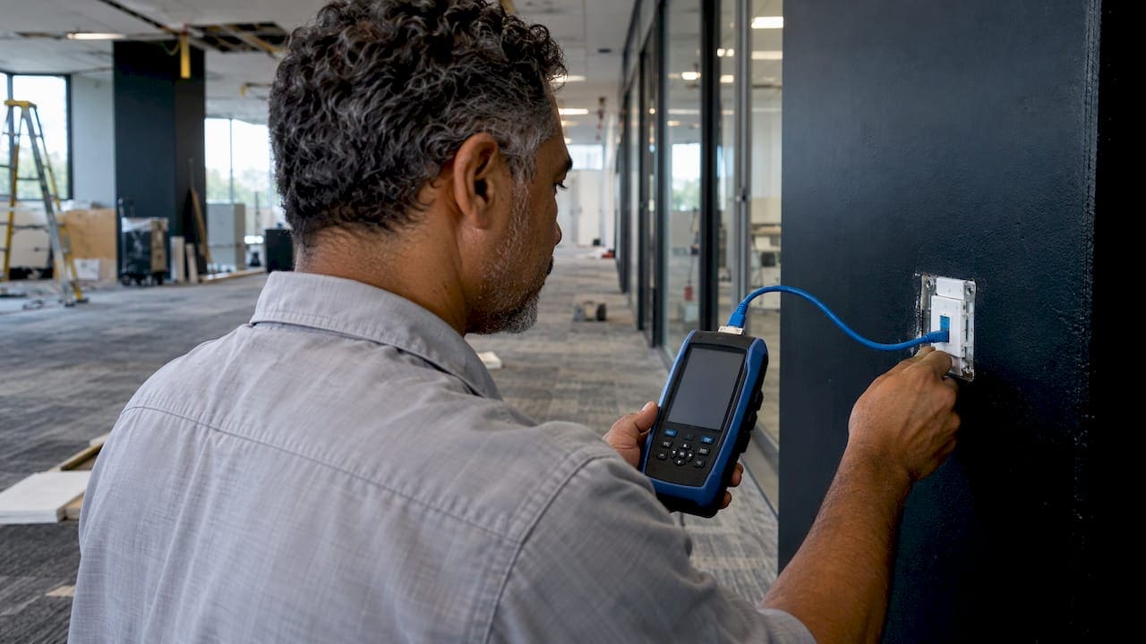
A cable certification failure is a measurement, not a verdict on the cable. In most cases the cause is the termination at one end, a patch cord, or the tester setup, and the report tells you which parameter to chase. Read the failed parameter, margin and worst pair first. Then correct the cause, retest and keep the record of both results.
This guide is written for IT directors, facilities managers and project managers who receive failed reports on an office buildout or upgrade. It covers what the numbers mean, the usual causes, a troubleshooting order that avoids wasted re-terminations, when to replace a run, and what documentation to keep.
TL;DR
- Most failures trace to termination problems rather than the cable itself, so read the report before cutting anything.
- Confirm the tester setup first: test standard, link model, adapters, reference, software and calibration.
- A negative margin fails, a positive margin passes, and a marginal result is smaller than the tester’s accuracy specification.
- Retest every repair and document the corrective action with a new passing test.
- Agree in writing how marginal results are treated before testing starts.
What a certification failure actually tells you
A certifier measures a link against the limits of a chosen standard and reports an overall result. If any single parameter fails, the overall result is FAIL for that run is not what this means; the point is simpler: one failing parameter is enough, even if every other line passes. That is why the summary page matters less than the line that failed.
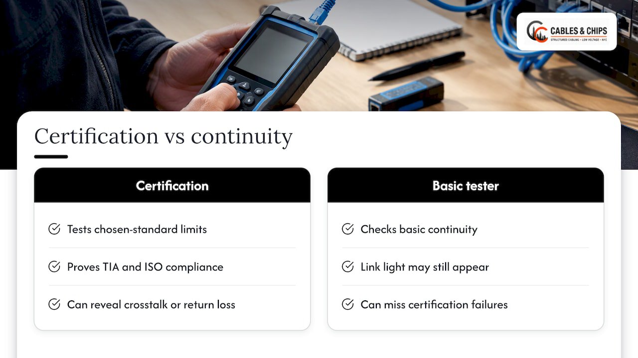
Certification differs from simple continuity checks. It is the most rigorous testing method and the only way to prove cabling meets TIA and ISO standards, which is also what manufacturer warranties usually rely on. A cable that lights a link on a basic tester can still fail certification on crosstalk or return loss.
PASS, FAIL and marginal
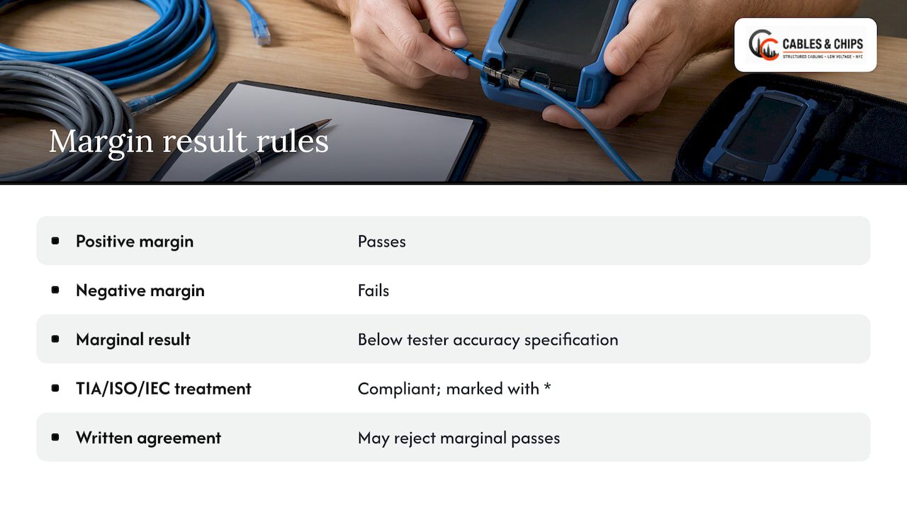
Each parameter has a margin: the measured value relative to the selected limit at the worst-case frequency. A positive margin passes and a negative margin fails. A marginal result is one whose margin is smaller than the accuracy specification of that parameter on the tester.
Marginal results cause the most disputes. TIA and ISO/IEC standards treat marginal passes as compliant and mark them with an asterisk. A customer can, however, agree in writing beforehand that marginal results are unacceptable. If you manage a building or an IT budget, put that decision in the contract or scope of work, not in an email after the failed report arrives.
The most common causes of failed links
There are four families of causes. Knowing them tells you where to look first.
1. Termination faults
Untwisted pairs at the jack, a pair crossed at the punch-down, a poorly seated plug or a damaged connector account for most failures. Most certification failures come from termination issues rather than the cable. Another installer guide says the same: most failures are fixed by re-terminating, while damaged cable has to be replaced. Crosstalk failures such as NEXT are a typical sign, because pair twist protects against crosstalk and loses its effect when it is unwound too far.
2. Tester configuration
A surprising share of failures is not in the cabling at all. Tests fail when the technician selects the wrong test standard, uses the wrong link model (Permanent Link versus Channel), or works with an out-of-calibration instrument. Running a Cat 6A limit on Cat 6 cabling will produce failures that no re-termination can fix.
3. Patch cords and connectors
Patch cords use stranded conductors, so strands can break over time with repeated bending. A bad patch cord used as a test lead or inside a Channel test can fail an otherwise good run. Poor connectors and bad patch cords are listed among the common causes of failures alongside installation errors and cable damage.
4. Physical damage and shielding faults
Kinks, over-tight bend radius, crushed cable and strain from zip ties or staples show up as return loss or length anomalies. With shielded systems, shield continuity is its own pass or fail item: an improperly bonded drain wire fails the link even when the conductors perform well. For bonding and grounding practice, see our guide to shielded cabling grounding and testing.
How to read the failure report
Start at the summary, find the parameter flagged, then open that parameter’s detail. The summary flags specific parameters such as Wiremap, Length, NEXT or Return Loss that fell outside TIA-568 thresholds. The selected test limit decides which parameters, frequency range, link model and thresholds apply, so the limit name on the report is the first thing to check.
For each result, note the margin, the worst pair or pair combination and the worst-case frequency. Distance-to-fault data is useful, but treat it as a clue rather than proof.
What each parameter means
Common copper parameters include length, propagation delay, delay skew, DC resistance, insertion loss, NEXT, PS-NEXT, ACR-F and return loss. The definitions below follow the TIA-568 field test specification, and the likely causes are what installers usually find first.
| Parameter | What it measures | Typical place to look |
|---|---|---|
| Wire map | Whether all eight wires reach the correct pins | Opens, shorts, crossed or split pairs at either termination |
| Length | Electrical length of the link | Runs beyond the limit, wrong NVP setting, open in the cable |
| Insertion loss | Loss of signal strength along the link | Excess length, poor connector, wrong cable category |
| NEXT | Difference between the transmitted signal and crosstalk received at the same end | Untwisted pairs at the jack or plug, poor connector seating |
| ACR-F | FEXT minus insertion loss | Crosstalk at the far end, termination quality |
| Return loss | Difference between transmitted and reflected signal power | Impedance changes: kinks, poor connectors, damaged cable |
Wire map comes first
Correct a wire-map error before you trust anything else on the report. An open wire can make insertion loss and derived measurements undefined, which means a page full of failures can come from one bad pin.
Time-domain diagnostics
Advanced certifiers offer time-domain tools such as HDTDX and HDTDR that show where crosstalk or an impedance discontinuity sits. That helps an installer separate termination faults from physical damage to the cable. A fault near zero distance points to the connector at the tester end. A fault mid-run points to the pathway.
A troubleshooting order that saves time
The common mistake after a failure is immediate, unsystematic re-termination. Work in this order instead.
- Verify the tester setup. Confirm test standard, link model, adapters, reference, software version, NVP, temperature and calibration date. A tester stored somewhere colder or warmer should reach steady-state temperature before you set the reference.
- Read the failure. Note the parameter, margin, worst pair and frequency, and any distance to fault.
- Inspect both ends. Look for untwisted pairs, damaged jackets, loose seating and the wrong wiring scheme.
- Re-terminate the failing end and retest. If the distance-to-fault pointed to one end, start there.
- Re-terminate the other end and retest. Only do this if the first did not clear it.
- Inspect the run. If it still fails, look for damage along the cable: crushed sections, tight bends, staples, and proximity to power.
- Swap suspect patch cords and adapters. Do this early if several unrelated links fail in the same way, since a shared test accessory is more likely than many bad runs.
A useful pattern check: if every link on a floor fails the same parameter, suspect configuration or accessories. If one link fails and its neighbors pass, suspect that run’s terminations.
Repair or replace
The fix follows the cause. Correct wiring and termination faults, replace defective connectors or patch cords, and repair or replace damaged cable. A cable segment with defects may need replacement.
In practice:
- Wiring errors: re-terminate to the correct scheme and retest.
- Poor termination or connector: cut back, re-terminate with a fresh jack or plug, retest.
- Bad patch cord: replace it and retest the link.
- Crushed or kinked cable: replace the run, because a damaged section cannot be restored by re-terminating.
- Shield bonding fault: correct the bond to the grounding path, then retest.
- Wrong cable category: pull the correct cabling. No setting changes this result.
On a project with a tight schedule, replacing a short run in an accessible pathway is often faster than a third round of re-termination. Decide that at step 6 of the order above, not after the day is gone.
Retesting and documentation
Every repaired link is retested. The corrective action is documented and followed by a new test that proves the corrected Permanent Link meets the performance requirements. Keep the intervention history too: do not silently delete failed results and replace them with a final pass. The failed test, the repair and the passing test together show the work was done properly.
What a good report package contains
One public-sector specification is a useful model. It asks each report to include the tester make, model and serial numbers, adapters, software version, calibration date, operator, cable ID, project name, test specification, date and time, overall result and wire-map results. Ask for the same on your own project, along with the plot data, which is typically required for certification testing.
Tie the test files to your as-built records. Our as-built documentation guide explains how labeling, floor plans and test results fit together so the next technician can trust them.
Preventing failures before the first test
Prevention comes down to installation discipline and a controlled test process.
- Keep pair twist to the termination point. Strip only what the jack requires.
- Respect bend radius and pathway limits. Avoid tight zip ties and staples.
- Use matched components. Cable, jacks, patch panels and cords should be of the same category as the limit you test to.
- Calibrate on schedule. Verify the tester’s calibration every 12 months at an authorized service center and set the reference regularly.
- Choose the right link model. Permanent Link for installed cabling, Channel when the contract calls for it.
- Write the rules down. Specify the test limit, the report format and the treatment of marginal results before work starts.
- Update test methods with the hardware. The TIA standards committee has noted that field-terminatable plugs and newer hardware need updated, precise test methods.
For more on standards, read our TIA standards compliance guide and why testing matters before cabling goes into use. If you are choosing instruments, our buyer’s guide to cable testing tools covers what matters for commercial work.
Our perspective
We treat certification as the final step of the installation, not a separate task added at the end. A failed link is information, and our approach is to read it, find the cause and fix that cause once.
After more than 40 years working in commercial environments in New York City, we design the process around three habits. First, we agree the test standard, link model and report format with you before the first cable is pulled. Second, we label and document each run so a failure can be traced to a specific jack and panel port. Third, we keep the failed result, the repair and the passing retest together in the handoff package.
In occupied buildings, riser access, after-hours windows and shared telecom rooms leave little room for guesswork. A systematic order of work avoids repeated visits and keeps your schedule intact. Clean, documented and tested work is what we aim to hand over every time.
Ken
Get your cabling tested and certified in NYC
If you have failed reports on a current project, or you want new cabling certified to a stated standard with documentation you can file, our team can help. We are licensed and insured, we offer a no-obligation site survey, and we cover testing and certification as part of structured cabling work across New York City. See our cable testing and certification service or the full services list, and schedule a site survey.

For new runs, our structured CAT6 and CAT6A installation work is terminated and tested to the limit you specify.
FAQ
Can a good cable fail certification?
Yes. The cable can be sound while the termination, patch cord, adapter or tester setup is not. A wrong test standard or link model, or an out-of-calibration tester, can cause a failure on good cabling. Check the setup before replacing anything.
What does an asterisk on a passing result mean?
It marks a marginal pass, where the margin is smaller than the tester’s accuracy specification. The standards consider it compliant, but you can agree in writing beforehand that marginal results are not acceptable. Decide this in the scope of work.
Should I re-terminate right away after a failure?
No. Read the failed parameter, margin and distance-to-fault first, then re-terminate the end the data points to and retest. Immediate, unsystematic re-termination is the most common mistake after a failed test.
When does a run need to be replaced?
When the cable itself is damaged, for example crushed, kinked or cut. Most other failures are resolved by re-terminating or replacing a connector or patch cord. Retest any repair either way.
What should I ask for in a certification report?
Ask for the tester model and serial number, calibration date, test limit, operator, cable ID, date and time, overall result and wire-map results, plus plot data. Keep failed and corrected results together, as described in the documentation section above.
Sources
- Cable Failed Certification: What to Do Next
- How to Read a Cable Certification Report
- Copper Cabling Troubleshooting Handbook
- Cabling Certification Failure Rate: Why Links Fail
- Why Does My Cable Fail Certification?
- Copper Certification Results Explained
- Field Test Specifications, ANSI/TIA-568-C
- Case Study 5: NEXT Fails Due to Termination
- Top 10 Cable Testing Mistakes
- Certification vs. Qualification
- How to Certify a Structured Cabling Network
- RCIT Cable Certification Testing specification
- Keeping Structures Connected: Updated Standards for Telecom Cabling