
BMS Cabling: Types, Standards and Installation Guide
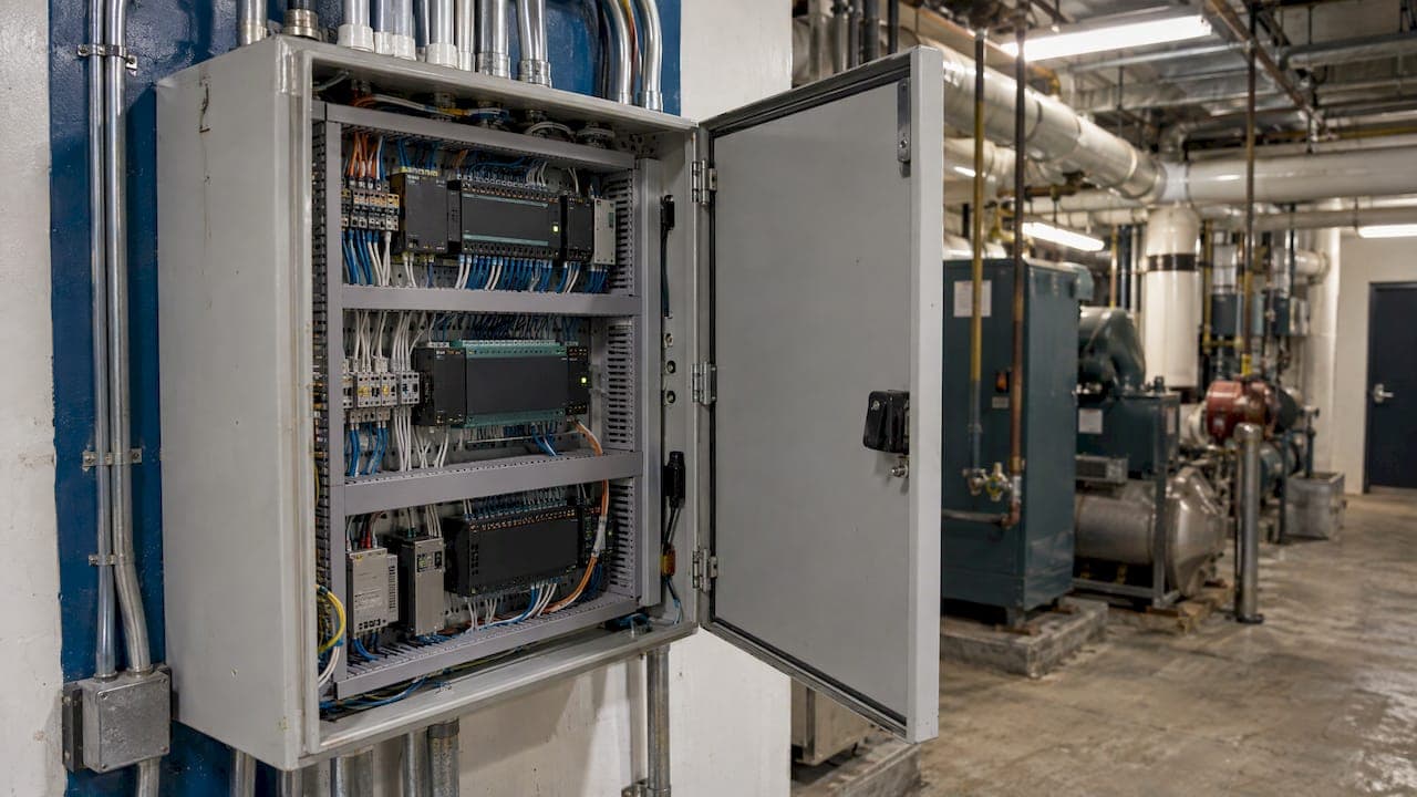
BMS cabling is the low voltage wiring that links a building management system to the controllers, sensors, actuators and network switches it supervises. It is not one cable. A typical building uses shielded twisted pair for RS-485 trunks, structured Cat6 or Cat6A for IP-based controllers, fiber for long backbone runs, and plenum-rated control cable for field devices. The cabling is built once and lives behind the ceiling for decades, so the choices made at install decide how reliably the HVAC, power and access systems talk to each other. For New York City offices and secure facilities, we design, install, label, test and document these runs as part of our low voltage cabling services.
TL;DR
- BMS cabling combines several cable families: RS-485 twisted pair for BACnet MS/TP and Modbus RTU, Ethernet (Cat6/Cat6A) for BACnet/IP, fiber for backbones, and control cable for field devices.
- RS-485 trunks must be daisy-chained, terminated at both ends, and shielded with the shield grounded at one end only. Star and T-tap wiring causes reflections and dropped devices.
- Keep signal cable away from power wiring, use plenum-rated jackets above ceilings, and follow the 2026 NEC’s consolidated limited-energy articles.
- Label both ends, color-code by function and deliver as-built documentation. This is what makes the system maintainable.
- Plan the cabling with the network team, not only the controls contractor, because BMS devices now share IT switches and closets.
What BMS cabling connects
A building management system (BMS) is the central software layer that oversees, visualizes and configures a building’s mechanical and electrical systems. Engineers separate it from the building automation system (BAS), the control layer that actually runs equipment and must keep operating even if communication with the BMS is lost. In daily speech facilities teams use the two terms loosely, and the cabling serves both.
DigiKey’s overview describes four layers in a BMS: supervisory, server/application, field controller, and input/output. Cabling exists at every layer:
- Supervisory and server layer: Ethernet to workstations, servers and the BMS front end.
- Controller layer: Ethernet or RS-485 between controllers, depending on the protocol.
- Input/output layer: low voltage signal and power wiring to thermostats, dampers, valves, meters and sensors.
The same system often touches fire alarm interfaces, lighting controls, elevators, metering and access control. Each needs a defined path, a defined cable and a defined termination point.
BMS cabling versus BMS network cabling
The two phrases overlap, and projects go wrong when nobody defines where one ends and the other begins.
BMS cabling is the broad term: everything that carries a signal or low voltage power for the system, from a temperature sensor’s two-conductor cable to a fiber uplink.
BMS network cabling is the part that carries data between intelligent devices: controllers, gateways, supervisory servers and switches. It is either an RS-485 serial trunk or standards-based Ethernet.
The distinction matters because the two halves are usually owned by different people. The controls contractor wires sensors and actuators. The IT team owns the switches, VLANs and closets. When BMS controllers move onto the corporate or a dedicated Ethernet network, the network half should follow structured cabling practice: Cat6 or Cat6A to the controller, patch panels, tested links and labeled ports. That is the work covered in what structured cabling is, and it is the half that benefits most from a single accountable contractor.
Cable types by protocol
Protocol decides cable. The table summarizes the common cases.
| Protocol or link | Typical cable | Key limits |
|---|---|---|
| BACnet MS/TP, Modbus RTU, N2 | Shielded twisted pair (RS-485) | Daisy-chain only, termination at both ends, about 4,000 ft per segment |
| BACnet/IP, Modbus TCP | Cat6 or Cat6A Ethernet | 100 m per channel, then switch or fiber |
| Backbone between closets or floors | Single-mode or multimode fiber | Distance, not copper limits |
| Field sensors and actuators | Plenum-rated control cable, 18 AWG or larger | Separate from power, labeled both ends |
| Device power (24 V) | Two-conductor stranded cable | Sized for voltage drop |
RS-485 trunks: BACnet MS/TP and Modbus RTU
RS-485 is an electrical standard for half-duplex multidrop communication over one twisted pair. Kele explains that Modbus RTU, Johnson Controls N2 and BACnet MS/TP all use RS-485, with a single twisted pair plus a reference wire.
Typical manufacturer requirements for MS/TP wiring are specific. KMC Controls calls for 18-gauge shielded twisted pair with capacitance of no more than 50 pF per foot, with up to 128 master devices on one network. A BACnet standard proposal describes 100 to 130 ohm impedance and a 1,200 m reach with AWG 18 cable at lower baud rates. Another controller manufacturer limits a segment to 1,219.2 m and 32 devices.
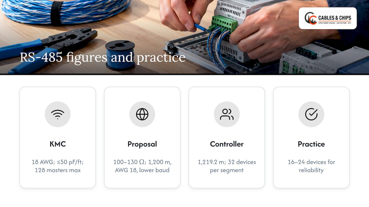
In practice, many integrators keep segments to 16 to 24 devices for reliability, well under the 32 unit-load ceiling. Always check the controller manufacturer’s cable specification before ordering. Substitutes are generally acceptable only when their resistance and capacitance per foot are as low as or lower than the recommended cable.
Ethernet: BACnet/IP and Modbus TCP
For IP controllers, an Ethernet cable such as Cat5e or Cat6 is used, and it can be run in star, ring or series layouts, but a run is limited to 100 meters before it must switch to fiber. That is the standard channel limit for twisted-pair Ethernet, and it applies to every controller-to-switch link.
Federal projects show where specifications are heading. The GSA’s May 2024 technical guide requires Cat6 with certified RJ45 and patch panels for any new cabling, accepts plenum-rated Cat5e only in existing installations, and requires Cat6A on the device side of wireless components. It also requires all Ethernet cabling to follow BICSI standards. Private owners are not bound by GSA rules, but a Cat6A backbone to controllers is a sound way to avoid recabling when devices are upgraded. Our structured CAT6 cabling installation covers CAT6 and CAT6A runs of this kind.
Fiber for backbones
When a riser or campus link exceeds copper distance or runs through electrically noisy areas, fiber carries the BMS network between telecom rooms. The decision logic is the same as for any backbone, and our CAT6A vs fiber decision guide walks through it. Fiber also pairs with the fiber installation work for termination and testing.
Field device cable
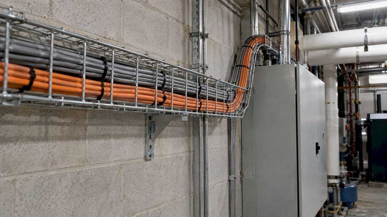
The I/O layer is where most mistakes hide, because the cable looks simple. The University of Florida’s March 2024 standards require plenum-rated jackets on control cables under 50 VAC/VDC, no wire smaller than #18 AWG unless it is pre-manufactured cable, a gray jacket for I/O signal wire and orange for field-device power wiring. Color conventions like these are owner-specific, but having one at all is what lets a technician trace a circuit years later.
Routing and separation rules that prevent comms faults
Most BMS network problems are intermittent: a controller drops offline in the afternoon when a large motor starts, then comes back. Routing discipline prevents this.
- Separate signal from power. Wayne State University’s standards require at least 12 inches between noisy power lines and communication or signal cables. Florida’s standards require DC conductors run separately from AC and cross at 90 degrees. Your own spec may differ, and the code has its own separation rules. See our guide on when codes require separation between low voltage and power.
- Daisy-chain RS-485. Wayne State’s standards call for point-to-point daisy-chain wiring with no T-taps, stubs, stars or spurs. ACI’s guidance for its controllers says the same: no star or T wiring.
- Terminate the ends. RS-485 termination resistors match the cable impedance, typically 120 ohms, and absorb reflections. Without them, reflections corrupt data at baud rates above 9600. A common check is about 60 ohms measured between the two conductors with devices powered off, as described in the WSU specification’s companion guidance; follow the manufacturer’s procedure on your devices.
- Ground the shield at one end. A shield grounded at both ends can create a ground loop. The controller vendor’s instruction governs which end.
- Do not splice trunks. Florida’s standards prohibit splicing communication cable unless a terminal strip and enclosure is used.
- Support the cable properly. The same standards require j-hook raceway spaced no more than 4 feet apart above accessible ceilings, 25% spare capacity in conduit sizing, and conduit for runs at or below 8 feet in Wayne State’s spec.
These are university design standards, so treat them as proven examples of good practice rather than universal law. They are the kind of detail a spec should contain, and the kind a field crew should be able to explain.
What the 2026 NEC changes for BMS wiring
BMS wiring is limited-energy wiring, so the National Electrical Code (NEC), the model electrical code adopted by states and cities, applies. Two changes matter.
First, the 2023 edition reorganized the rules. NECA’s training material explains that Article 722 now holds listing requirements for Class 2 and 3 cables, that Class 1 circuits moved to Article 724, and that Article 725 now covers only Class 2 and Class 3.
Second, the 2026 edition goes further. According to EC&M’s review, limited-energy rules are consolidated into Articles 720 through 723, 742 and 750, covering general methods, power sources, cables, raceways, overvoltage protection and grounding. New Section 300.13(E) requires cable ties used to secure and support cable to be listed and identified for that purpose, and 300.4© requires replacing wiring damaged by overheating, fire or water.
Which edition applies depends on what New York City, New York State, or New Jersey, Connecticut and Pennsylvania have adopted, and on the authority having jurisdiction for your building. Confirm with your electrical engineer or the local authority. For a plain-language walk-through of what changed for IT teams, read our NEC 2026 low voltage summary. For jacket ratings and old cable left in ceilings, see our plenum and abandoned cable rules.
Where BMS cabling meets security and access control
BMS projects rarely stand alone. Door controllers, intercoms, cameras and occupancy sensors often share pathways, closets and sometimes the same network. A few pairings come up repeatedly:
- Electrified locks need power and control conductors sized and routed together. A maglock installation guide shows how power and release wiring fit into a compliance checklist, even though local codes differ.
- Cameras on PoE share the 100 m channel limit with BMS Ethernet. See our guide to CCTV cable types and the 100 m limit.
- Access control runs have their own requirements, covered in our access control cabling requirements.
Coordinating these at design time means one pathway plan, one labeling scheme and one set of test records, instead of three trades each pulling their own cable.
Labeling, color coding and documentation
Cabling that works on day one but cannot be traced on day 700 is a maintenance cost. The standards reviewed here agree on what to record:
- Both-end labels. Wayne State requires communication cables labeled on both ends with the network jack number or supervisory device origin, and sensor wiring labeled on both ends with the point name. The label format is approved by the BAS manager before installation.
- Color-coding. The GSA requires BMC system device cables to be color-coded to a defined scheme and labeled to show the type of device they connect.
- Cable type and switch-to-switch links. Record what cable was installed, because the wrong cable causes poor signal quality and unstable transmission when links exceed the attenuation limit.
- Panels, addresses and layers. Document every panel, controller address and network layer.
Deliver this as as-built drawings plus test results. Our as-built documentation guide lists what a complete package contains. For Ethernet links, certification test reports prove each run meets its category rating, and they are the record a facilities team will want when a controller goes offline.
Who should own the cabling
GSA’s guide encourages project managers to let vendors handle all cabling for BMC devices connecting to the GSA switch, and states that GSA IT does not take responsibility for cabling not installed to its guide and industry standards. The principle applies to any owner: if nobody owns cabling quality, nobody answers when it fails.
A practical scope split for a commercial project looks like this:
| Scope | Owner |
|---|---|
| Controllers, programming, BMS software | Controls contractor |
| Network switches, VLANs, addressing | IT department |
| Ethernet cabling, fiber, patch panels, racks, testing, labeling | Low voltage contractor |
| Power circuits and conduit for line voltage | Electrical contractor |
General contractors should write the cabling scope into the bid package explicitly, including who tests, who labels and who delivers documentation.
A BMS cabling checklist for project teams
- List every device type and protocol, and map each to a cable family.
- Check the manufacturer’s cable spec for each RS-485 device before ordering.
- Plan pathways with separation from power and spare conduit capacity.
- Specify jacket ratings for the space, plenum above ceilings.
- Set the labeling and color scheme before the first pull.
- Confirm termination and shield grounding method per trunk.
- Test every run and keep the reports.
- Deliver as-built drawings and update closet documentation.
Our approach to BMS cabling
Most BMS network problems we are asked about are not software problems. They are cable problems: a trunk wired as a star, an unlabeled run, a closet nobody can trace.
Our view is that building systems now share the same network as everything else, so the cabling should be built the same way: designed, tested, labeled and documented. We bring more than 40 years of work in New York City commercial environments to that, and we are licensed and insured. We focus on clean, documented, organized installations, because that is what keeps a system serviceable after the install crew has left.
If your project has controllers going onto the network, new IDF closets or an old ceiling full of abandoned cable, start with the cabling. Your network is only as strong as the infrastructure behind it.
Ken
Plan your BMS cabling with Cables & Chips
We install and test structured CAT6 and CAT6A cabling, fiber, server racks and MDF/IDF closets, and we clean up abandoned cable for commercial offices and secure facilities across New York City. Our site survey is no-obligation, and our team responds locally and quickly.
If you are moving controllers onto your network, building out a floor or reorganizing a telecom room, schedule a site survey and we will walk the pathways with you. You can also review the full list of low voltage services before you call. For projects that include shared infrastructure, our guide on cabling in multi-tenant buildings covers pathways and riser coordination.
FAQ
What is BMS cabling?
BMS cabling is the set of low voltage cables that connect a building management system to its controllers, sensors, actuators and network equipment. It includes RS-485 serial trunks, Ethernet, fiber and field device control cable. Each carries a different kind of signal and has its own installation rules.
Can Cat6 be used for BMS networks?
Yes, for Ethernet-based protocols such as BACnet/IP and Modbus TCP, where Cat5e or Cat6 is the normal medium up to 100 meters per link. It does not replace the shielded twisted pair that RS-485 protocols such as BACnet MS/TP require. Use the cable each protocol calls for.
What does BMS stand for in networking?
BMS stands for building management system. In networking terms it is the group of controllers and servers that monitor and control HVAC, power and other building systems, usually over BACnet, Modbus or similar protocols on RS-485 or Ethernet.
How far apart should BMS and power cables be?
It depends on the specification and the code. University standards reviewed here call for at least 12 inches from noisy power lines and 90-degree crossings. Your engineer’s spec and the local electrical code set the binding distance, so confirm it before pulling cable.
Who should install and document BMS cabling?
The controls contractor typically handles sensors and programming, while a low voltage contractor handles Ethernet, fiber, racks, testing, labeling and as-built records. Defining that split in the bid package avoids gaps in responsibility.
Sources
- Definitions and terminology, Consulting-Specifying Engineer
- What are BACnet control points and devices in building automation systems?
- Networking Sensors for Building Management Systems, DigiKey
- Networking 101: BAS Network Cabling, Kele
- KMC Controls Digital Designer’s Guide
- BACnet MS/TP wiring proposal, STK-013-2
- ACI Immersion Series installation guide
- BACnet MS/TP Segment Sizing, EngineersUniverse
- GSA Building Technologies Technical Reference Guide v3.0
- University of Florida 253000 Building Automation standards
- Wayne State University Smart Facility Specifications and Standards
- NECA, Wiring for Safety
- Top 25 Changes to the 2026 National Electrical Code, EC&M