
How Open Office Cabling Is Planned for IT Pros
Most open office cabling disasters are not installation failures. They are planning failures. Understanding how open office cabling is planned before a single cable is pulled separates networks that perform reliably for years from ones that generate help desk tickets every week. This guide covers the full planning sequence: site survey, open office cabling layout design, cable management, installation coordination, and testing. Whether you are managing a new fit-out in Manhattan or refreshing an aging infrastructure, the decisions made on paper determine what happens on the floor.
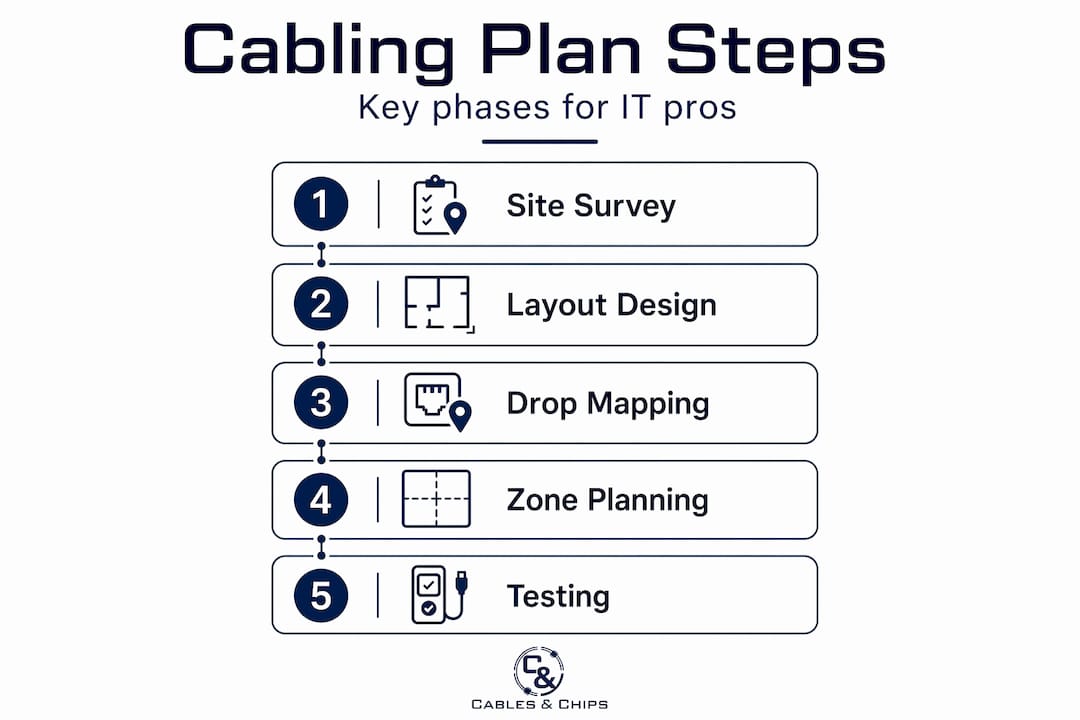
Table of Contents
- Key takeaways
- How open office cabling is planned: starting with the site survey
- Designing the open office cabling layout
- Cable management strategies and labeling
- Coordinating installation and ensuring proper testing
- My take on what actually separates good plans from bad ones
- Plan your open office cabling with Cables
- FAQ
Key takeaways
| Point | Details |
|---|---|
| Start with a site survey | Map physical layout, cable routes, and MDF/IDF placement before any design work begins. |
| Centralize your telecom room | A centrally located MDF/IDF reduces average cable lengths and keeps runs within standards. |
| Apply zone cabling for flexibility | Ceiling consolidation points reduce long home runs and improve moves, adds, and changes. |
| Label and document everything | Both ends of every cable should be labeled with consistent naming tied to a master document. |
| Coordinate with construction timelines | Cabling installed before ceiling tiles and flooring costs less and causes fewer disruptions. |
How open office cabling is planned: starting with the site survey
Before you design anything, you need an accurate picture of the physical space. A site survey is not optional. It is the foundation on which every other planning decision rests, and it should happen before the office fit-out begins, ideally while walls are still open and ceilings are accessible.
The survey captures several categories of information:
- Physical layout and dimensions: Floor plans with column locations, wall types, and ceiling heights
- Cable pathways: Potential routes for cable trays, conduits, underfloor ducting, or overhead ladder rack
- Obstruction mapping: Fire walls, structural beams, HVAC runs, and any existing containment or cables already in place
- Telecommunication room locations: Identify where the main distribution frame (MDF) or intermediate distribution frames (IDFs) will sit
- Building access and approvals: Confirm landlord or building management sign-off, local code requirements, and any union jurisdiction considerations
Centralizing telecommunications rooms balances cable lengths and significantly improves future-proofing and reliability. A telecom room positioned at one corner of a 20,000-square-foot floor will force cable runs that push against or exceed the 90-meter limit. Centered placement solves this structurally before the design phase even begins.
Pro Tip: Request architectural and MEP (mechanical, electrical, plumbing) drawings early. Overlay your proposed cable routes on these drawings to identify conflicts with HVAC, sprinkler lines, and electrical panels before you are working around them in the field.
The survey also identifies whether office planning decisions made by the design team affect cabling routes. Partition walls, raised flooring systems, and ceiling grid types all influence which cable management solutions are practical. Getting this information before cabling design locks in prevents costly redesigns.
Designing the open office cabling layout
With survey data in hand, the layout design phase translates physical constraints into a structured plan. This is where planning office cabling gets technical.
Workstation density and drop planning
Start by mapping workstation locations. Count devices per workstation: desktop or laptop, VoIP phone, and any secondary monitors with USB-C docking stations that require data ports. A standard workstation in a dense open office typically needs two data drops minimum. Add wireless access point locations, print stations, and any AV endpoints to the count. Every endpoint needs to be served without exceeding cable length limits.

Structured cabling standards limit copper cable runs to 90 meters, including patch cords on both ends. In practice, installers target 85 meters or less to leave headroom for patch cord lengths. This constraint directly shapes where switches and consolidation points must be placed on any given floor.
IDF-centric vs. zone-based cabling
The table below compares the two most common approaches in open office wiring guides:
| Approach | Best for | Trade-offs |
|---|---|---|
| IDF-centric (home runs) | Smaller floors, simpler layouts | Long cable runs on large floors, large cable bundles |
| Zone cabling with consolidation points | Large open floors, high density | Requires more planning upfront, additional hardware |
Ceiling consolidation points place PoE switches and patch fields closer to workstation clusters, serving defined zones and reducing long home runs. On a floor larger than 10,000 square feet, zone cabling is almost always the better choice. It reduces the volume of cable being pulled back to a central IDF, lowers material costs, and makes future moves and adds far simpler.
Pro Tip: When designing zones, draw a circle with an 80-meter radius from each consolidation point on the floor plan. Every workstation that falls outside that circle needs its own zone or a closer switch location. This visual check catches range problems at the design stage, not during installation.
Common cabling pathways to consider in your open office cabling layout include underfloor cable routing through raised floor systems, overhead cable trays or ladder racks above a drop ceiling, and surface-mounted cable raceways along walls or desk clusters in exposed-ceiling spaces.
Cable management strategies and labeling
A well-designed cabling layout can still fail operationally if the physical installation is disorganized. Cable management is what keeps the network maintainable over its full lifecycle.
Here is a practical sequence for building good cable management into the plan from the start:
- Specify containment by zone. Assign cable trays, raceways, or conduit runs on the design drawing before installation begins. Mixing uncontained cables with contained runs creates problems that compound over time.
- Use patch panels at every distribution point. Patch panels consolidate connections into a manageable interface and reduce clutter at the switch layer. Every port on a patch panel should map to a documented port at the workstation end.
- Install racks or cabinets at all distribution points. Structured cable enclosures protect hardware and create a clean, secure environment for switches and patch panels. Open-frame racks work in secure telecom rooms; lockable cabinets are better in shared or accessible spaces.
- Route cables to avoid tripping hazards. Cable raceways and underfloor systems keep cables out of walkways. Any cable crossing a floor or running under a desk must be secured or enclosed.
- Label both ends of every cable before termination. Use a consistent naming convention, such as floor-zone-port number (e.g., 3-A-12), and record it in a master cabling document. Proper labeling at both ends can save hours of fault diagnosis and reduce trip hazards.
- Store documentation digitally. Cabling maps, as-built drawings, and test results should live in a shared drive accessible to IT staff. Physical binders get lost. Digital records survive staff turnover and office moves.
The documentation point is frequently underestimated. Three years after installation, when a workstation cluster gets relocated and someone needs to repatch eight ports, the value of accurate as-built drawings becomes immediately obvious. Without them, technicians trace cables manually, which takes time and introduces errors.
Coordinating installation and ensuring proper testing
The sequence in which cabling work happens relative to the construction schedule determines both cost and quality. This is one of the most common places where open office projects go wrong.
The correct installation sequence follows the construction timeline closely:
- Site preparation: Confirm pathways are clear, telecom room locations are framed, and power for network equipment is roughed in
- Cable containment first: Install trays, conduit, raceways, and any underfloor ducting before pulling any cable
- Cable pulling: Run cables through containment with proper fill ratios; avoid overfilling trays, which causes heat buildup and physical stress on cable jackets
- Termination: Terminate both ends at patch panels and keystone jacks; follow T568B or T568A wiring standards consistently throughout
- Testing and certification: Test every run before devices connect to the network
- Device connection: Only after passing certification, connect switches, access points, phones, and workstations
Cabling installed before ceiling tiles, partitions, and floor coverings costs significantly less and causes far fewer disruptions than work done after finishes are in place. A project manager who sequences the telecom contractor correctly saves the client real money.
On the testing side, every cable should be tested and certified using standards-compliant testers before network launch. For CAT6 and CAT6A installations, this means channel and permanent link tests that verify insertion loss, return loss, crosstalk, and propagation delay. The test results become part of the permanent documentation package, which is critical for warranty claims and future troubleshooting.
Future-proofing is worth addressing at this stage too. Specifying CAT6A instead of CAT6 costs more upfront but supports 10 Gigabit Ethernet to the desktop and accommodates PoE++ devices without the thermal management concerns that arise with CAT6 in bundled runs. If the office will run high-density wireless or VoIP, the investment pays back quickly.
My take on what actually separates good plans from bad ones
I have worked on enough open office cabling projects to say with confidence that the technical specifications are rarely where these projects fail. The plans that go sideways almost always have the same root cause: the cabling contractor was brought in too late.
By the time some clients call us, ceilings are closed, partitions are up, and the construction crew has already covered the only practical cable pathway with a finished floor. What should have been a clean CAT6A installation becomes an expensive retrofit. I have seen projects where the rework cost more than the original installation would have.
The MDF/IDF placement issue is real too. I have walked into spaces where the telecom room was placed at the request of a real estate team that wanted the “storage closet” in a corner far from the network center of gravity. Every cable run on that floor paid the price. Moving a telecom room after construction is not a minor fix.
My strongest advice for IT managers and project managers reading this: get your structured cabling contractor into the planning conversation before the architect submits construction documents. Not after permits are pulled. Not during fit-out. Before. The questions a good low voltage contractor asks at that stage, about cable pathways, room placement, zone distribution, and future headroom, shape decisions that cannot easily be undone.
Labeling and documentation feel like administrative work, but they are actually a form of insurance. Every time I see a cable cleanup job where someone has to trace fifty unlabeled cables in a rat’s nest of a telecom room, I think about how a few hours of proper labeling during installation would have prevented days of remediation work later.
Your network is only as strong as the infrastructure behind it.
— Ken
Plan your open office cabling with Cables
Getting the planning right from the start is what Cables does every day for commercial offices, IT departments, and project managers across New York City. From initial site survey through final certification, the team at Cables & Chips manages the full scope of structured cabling for open office environments.

Services include CAT6 and CAT6A installation designed specifically for open plan layouts, professional cable testing and certification using standards-compliant equipment, and full documentation packages for every project. For offices dealing with existing infrastructure that needs organization, network closet cleanup services bring order back to telecom rooms that have grown messy over years of changes. With more than 40 years of experience in New York City, Cables & Chips brings the technical depth and project coordination skills that complex open office deployments require. Contact the team at 20 Vesey Street in Lower Manhattan to schedule a site survey before your next fit-out begins.
FAQ
How far can CAT6 cable run in an open office?
Structured cabling standards limit copper runs to 90 meters, including patch cords at both ends. In practice, most installers target 85 meters or less to leave room for patch cord lengths on each end.
What is the difference between IDF-centric and zone cabling?
IDF-centric cabling routes all runs back to a central distribution frame, while zone cabling uses intermediate consolidation points closer to workstation clusters. Zone cabling is more practical on large open floors because it reduces cable bundle sizes and simplifies future moves and changes.
When should cabling be installed during an office fit-out?
Cable containment and cable pulls should happen before ceiling tiles, partitions, and floor coverings are installed. Poor installation timing leads to higher costs and significant construction delays.
Why does MDF/IDF placement matter so much in open office planning?
The location of the telecommunications room determines average cable run lengths across the floor. A centrally placed MDF/IDF keeps most runs well within the 90-meter limit, while a corner placement can make portions of a large floor nearly unreachable with copper cable.
What does cable certification testing verify?
Certification testing checks insertion loss, return loss, near-end crosstalk, and propagation delay for every installed run. The results confirm that each cable meets the performance standard for its category, CAT6 or CAT6A, and provide documented proof of compliance for warranty and troubleshooting purposes.
Recommended
- Why Network Infrastructure Matters | Low Voltage Contractor NYC – Cables & Chips | Low Voltage Contractor NYC
- Structured CAT6 Cabling Installation NYC | CAT6 & CAT6a – Cables & Chips | Low Voltage Contractor NYC
- Cable Cleanup NYC | MDF IDF Cleanup & Network Closet Organization – Cables & Chips | Low Voltage Contractor NYC
- Partner With Cables & Chips NYC | IT Consultant & Network Installation Partner – Cables & Chips | Low Voltage Contractor NYC